Week 3
Getting started with Computer-Aided-Designing
This weeks assignment was to start getting familier with 2D and 3D Design tools. So, I started with surfing over the internet about CAD modelling. I learnt, using CAD it can provide a great aid in visualizing what we are trying to build. Earlier it was just imagination for me. Whatever I used to make, it was all direct. So, with a lot of fascination I choose to move ahead with Autodesk Fusion 360. While his lecture Neil shared about this software being free for students and teachers. I started with installing the software on my computer. I was like cutting a piece of cake.... Super Easy. Then afterwards I started with some video tutorials on Youtube. I am sharing a whole series of small small tutorials which helped me to learn better from the basic. The software seems to be very easy to understand and its intuitive interface is quiet easy to work with.
Video Tutorials ( Click to open )
The video tutorial taght me the basics about fusion 360 and along with the video I was making whatever he was making in the video. So initially I ended up making a work piece which involved few basic functions including fillets, extruding, 2D Sketches, 2D to 3D Modelling, Hole cuting, Press pull etc.
The Gif shows a series of steps which I followed to create the final work piece.
Earlier I was trying to put 6 pictures of what I made, but it made my page very lengthy, so I made a gif out of it using an online GIF Creator . I also tried GIFY. I downloaded the GIF but the size of the GIF was about 2.1 MBs so I tried Compressing it with an Online compression tool . After this the size of image was about 100 Kbs.
Download Fusion FileGetting started with Fusion 360 & Final Project
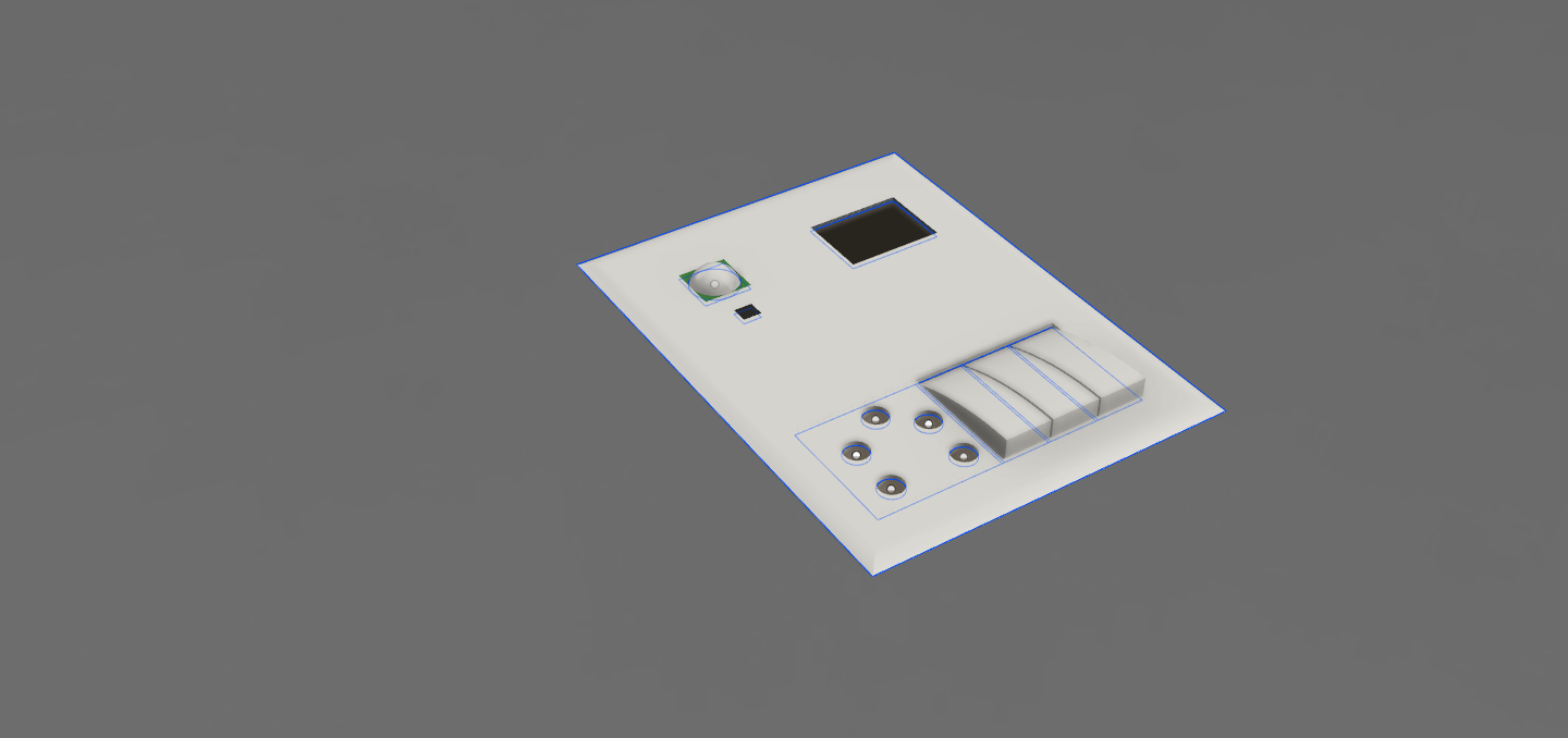
So , after learning the basics about fusion 360, I started my way towards the week's assignment that was to create a CAD design of Final Project. It was a bit trciky to draw a 3D Sketch, Because my drawing sucks... unfortunately. The drawing was about to have a lot of complexity, but somehow I managed to make something.
Here I am sharing my work. I tried different materials, different apperances, rendering, different processes/features etc.
I also tried rendering my design and the final outcome was :
 View all Drawings
Download Fusion File
View all Drawings
Download Fusion File
Getting started with Parametric Designing via openSCAD
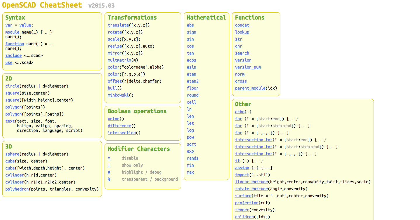
So, getting straight to the point I am completely new to Parametric Designing, So I started with reading Wiki about Parametric designing. Going through a WIKI I got to know its the coolest thing you can learn in designing...... There's a lot you can do with it, key and the lock models can be realized effectively with parametric designing. Without much ado I started with openSCAD, which is an open source program available for all the platforms and has no dependencies. P.S it can be installed very easily but their servers a bit slow, It bothered me while downloading.... well after evrything was in place I started with the basics... While surfing through their website there is this Cheat sheet which makes using openSCAD even more easy.... Plus a good thing which I like the most is its community. It has a very huge community online which can help you with complex designs..... So anybody looking forward with parametric designing can definately count on openSCAD.
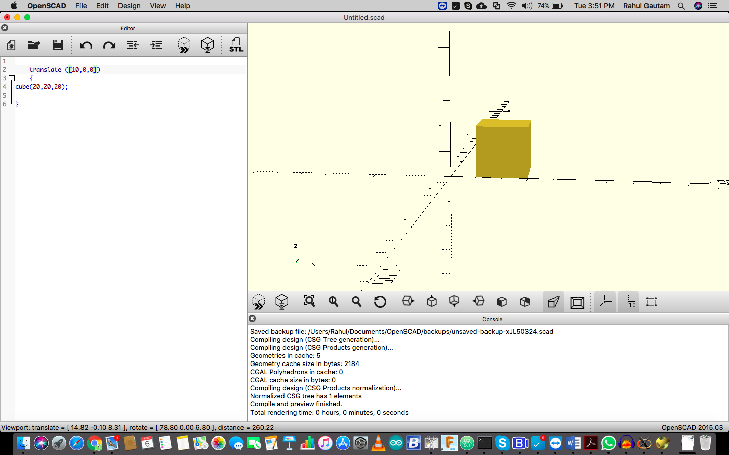
My First Body
I started with a cube and tried to move along one cordinate.
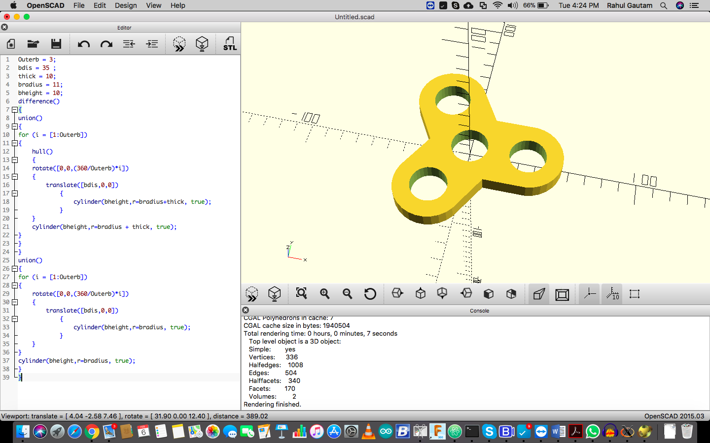
So now without much thinking I jumped into it and started with making a fidget spinner design. So, the first challenge was to understand what all parameters would be needed to make a parametric design of a fidget spinner. I started looking over the internet. I got to know, the paramters which are necessasary are :
> Number of outer bearings.
> Distance between bearings.
> Thickness
> Radius of bearing
> Height of bearing
Outerb = 3;
bdis = 35 ;
thick = 10;
bradius = 11;
bheight = 10;
difference()
{
union()
{
for (i = [1:Outerb])
{
hull()
{
rotate([0,0,(360/Outerb)*i])
{
translate([bdis,0,0])
{
cylinder(bheight,r=bradius+thick, true);
}
}
cylinder(bheight,r=bradius + thick, true);
}
}
}
union()
{
for (i = [1:Outerb])
{
rotate([0,0,(360/Outerb)*i])
{
translate([bdis,0,0])
{
cylinder(bheight,r=bradius, true);
}
}
}
cylinder(bheight,r=bradius, true);
}
}
 Veiw all Images
Download openSCAD File
Veiw all Images
Download openSCAD File
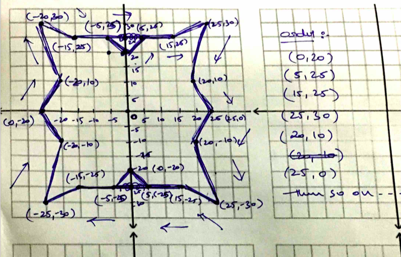
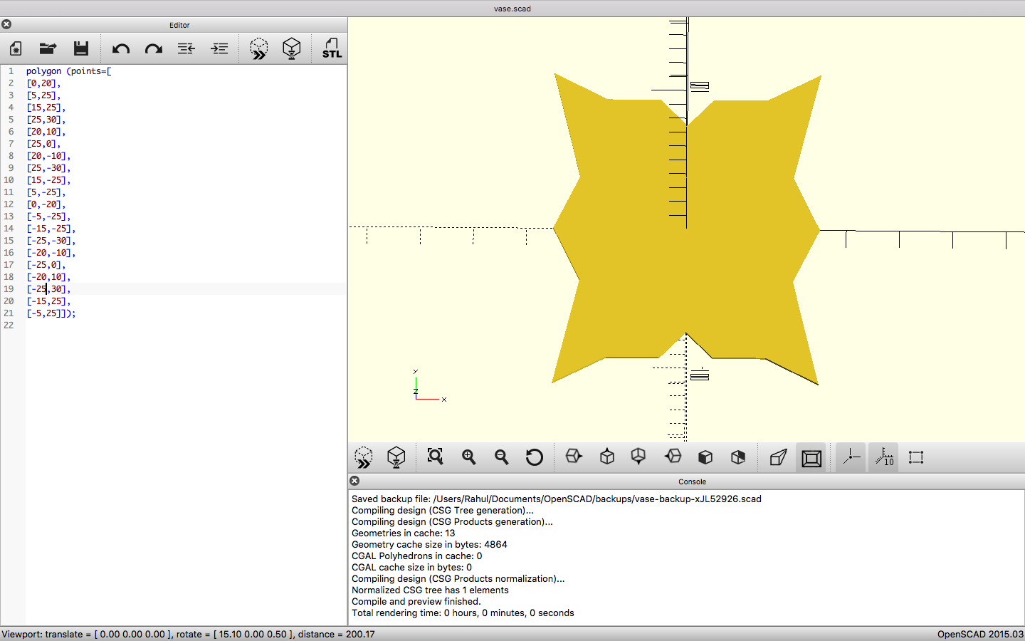
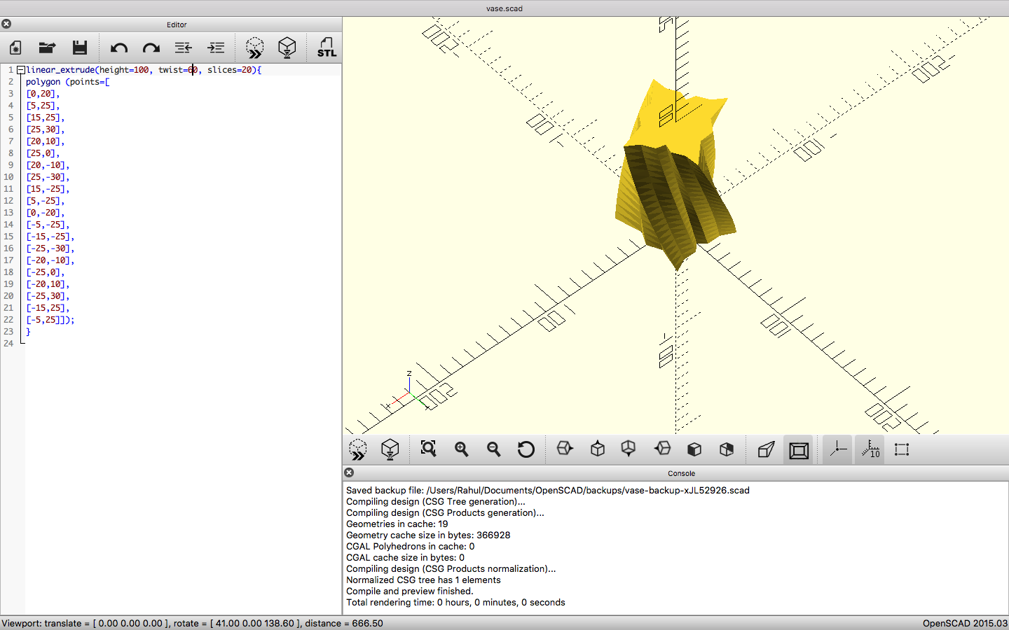
After this design I made a pen holder ( A twisted pen holder ). To make one I made an outline of a single layer of the holder which is as shown, and decided the order to make a closed path point by point :
I started with the first layer of the holder, and after that I used linear extrude function to create the final twisted holder.
 Download Holder's files
Getting started with GIMP
What I understood with GIMP was....... Its a classic photo editor which is free and its an alternative of Adobe Photoshop. For web we need pictures which are of smaller sizes and GIMP can be a perfect tool to do that. Apart for that it can also be used to manipulate images accordingly.
To work along with the software I decided to work on a particular image and try to remove its background.... I decided to do this because I thought it can be usefull for Product Presentation over the web.
Apart from that this time to create this GIF I used GIMP itself to create one.
 Veiw all Images
Download GIMP Files
Veiw all Images
Download GIMP Files
Contact Me
I am happy to talk you through any projects or run live demos to see how they look like.