Week 4
Getting started with Computer Controlled Cutting
This weeks assignment was to start getting familier with the cutting techniques followed by hands on with Laser cutter and Vinyl Plotter. Personally my experience for this was horrible. I did'nt know how to design and what to design ....... So after a lot of struggle I ended up with designing few things. I started up with Slicer for fusion 360. I downloaded a stl file of a lamp and then tried to slice it so as to make a press fit, but due to some reason ( I dont know yet ) their were few errors after the slicing, I played along with all the parameters but errors were not rectified.
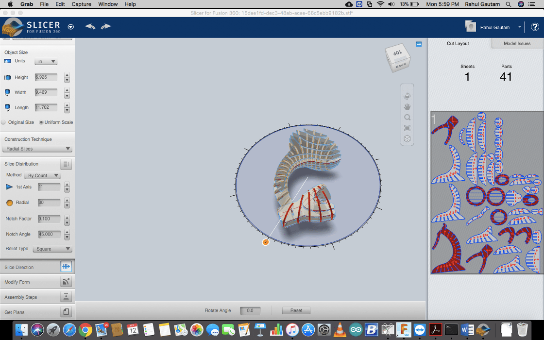
Download All Files Download Lamp Files
As the errors were not rectified so I dropped it for further brain storming afterwards and I started with Vinyl plotter.
Getting started with Vinyl Plotter
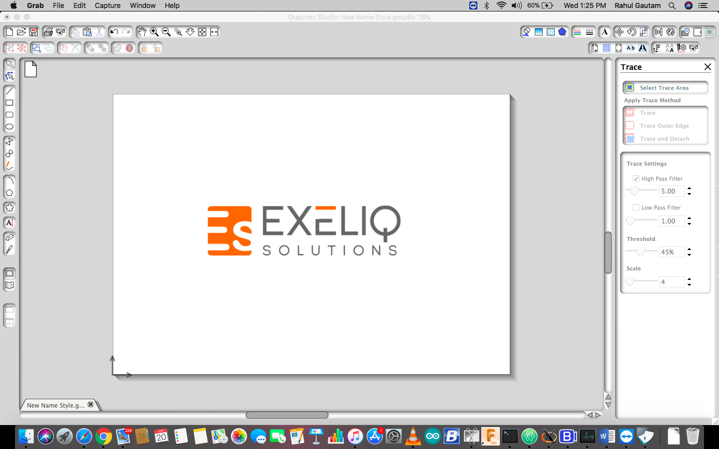
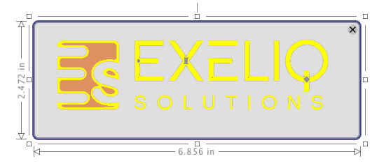
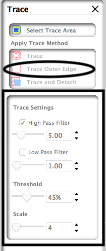
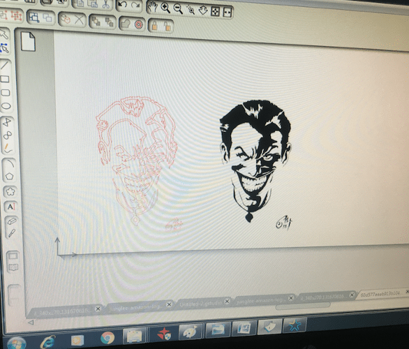
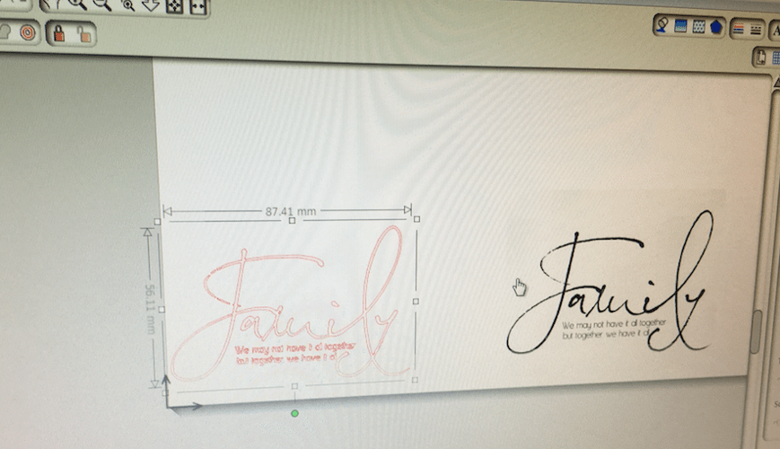
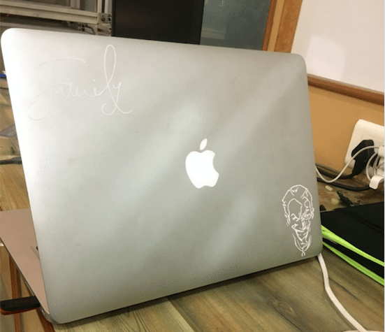
Graptech Studio. I decided to create a joker sticker for my laptop so I downloawed a black & white image from internet and imported it to the software, after that I marked a trace area and then played with the threshold settings and then finally it was sent to cut. Apart from that I tried to work with multiple colour cutting and I made my Company's logo with 2 colours. i.e orange and white.
To do that I traced the path in multiple steps rather than in a single go. After 1 step I changed the sheet and printed the 2nd step trace on a different colour sheet.
Here is the Workflow for cutting using Vinyl Plotter
Step 1: Open the File in Graphtec Studio
Step 2: Now click on the Select the trace area
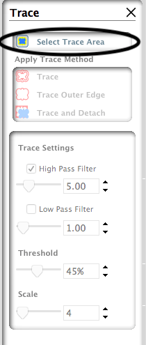
Step 3: Select Trace Area
Now from this menu you can play around with the threshold and make the trace
Step 4: Now that we have the trace, Move the original design and delete it

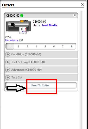
Step 5: Now using this button over the main window send the cut file to the Plotter

To Summarize
1. Import the desired image in the software.
2. Set the Size of the image and trace.
3. Remove the original Image.
4. Send the Cut to the plotter after setting the origin on the machine.
5. Weeding: Weeding, or the process by which unnecessary vinyl is removed from a design. Here under are the step for the weeding.
1. Lay your unweeded vinyl out on the table in a right-reading direction. Begin weeding from the upper right corner and work toward the lower left corner.

2. When working with designs that are ½” or smaller, tape out the entire cut? The designs you need should come up with the vinyl in one piece. Lay this on your weeding area sticky side up and hold the vinyl in place using spring clamps. This will allow you to weed away the excess
vinyl without causing any misalignment.

3. Only cut a weeding border and no weeding lines, except the ones needed to separate groupings. Carefully weed out openings, such as the
holes in the letters A, e and O. Cover the design in transfer tape like normal, carefully remove the backing paper and apply the design as
usual. You should be able to remove the transfer tape and excess vinyl without the risk of damaging your design.

                                                                                                        ~ Source: https://www.thinksai.com/
6. Now with the help of Transfer tape take the design from the sheet and paste it wherever you want to paste it, A handtool ( Knife ) may be helpful.
To learn how to use Transfer tape follow this video LINK
Here are some Stickers I printed

Note : Exeliq Solutions Logo subjected to copyright
Getting started with Laser Cutter ( Along with group Project)
For starting with Laser cutter I started with undertanding its working and about the KERF. What I understood with KERF is , its the dimention of material which gets burned off when laser cuts through it. Apart from that I also tested various combinations of Power and speed to understand the characterstics. . The software we used to cut is RD Works.
Measuring KERF & Testing combinations
For Measuring the KERF I made 10 cuts within a rectangle and the shifted all the cuts to one side, then measured the gap, and then divided the gap by 10, the final obtained value is the KERF of the laser cutter we are using, which is in our case is : 0.3mm
Calculation is as : Distance obtained after the cuts are shifted to one side = 3 mm and the total number of cuts = 10, So 3/10 = 0.3mm which is the KERF of the LASER.
Usage of Kerf
Kerf is an important paramter which must be kept in mind while designing..... as its the amount of material which would be sacrificed..... so tolerances should be made according to the kerf .....
A Wierd Experience with RD Works
I dont know if anyone has faced this before ....... I was trying to open a DXF file and the software was displaying nothing ..... the steps I followed were ..... I open the software > File > Open > (Selected file types as all files) > open my DXF > GO KID MAKE IT AGAIN ( Blank ).
But When I open the same file using this procedure ...... Navigated to file > Right click > Open With > RD Works ( Microsoft.. something chinize ) (P.S : RD works belongs to Microsoft ? ) > Door of heaven opens and here's your file ..... The same file which was blank last time. ( Annoying ..... wasted 1 hour to figure out whats wrong with Fusion .....)
This error has not been documented yet over the internet but during my regional reveiw I got to know that this software has been recently updated and it has some bugs.... they may go with furthur updates

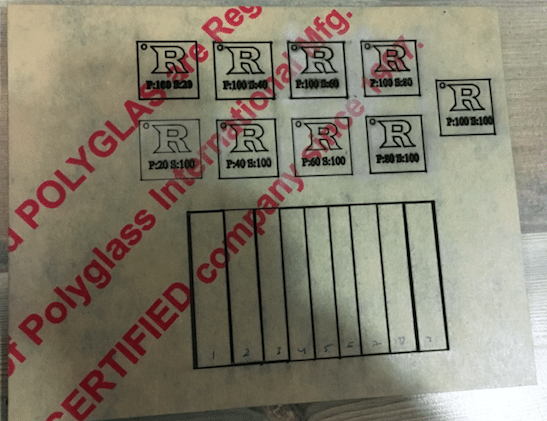
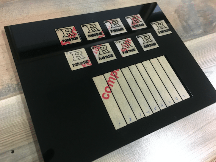
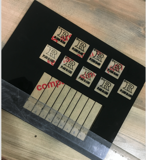
For Testing characterstics with different Power and speed combinations I made seperated coloured rectangles and configured them with different power and speed as shown in the picture. Ex: P : 100 S : 20 , it means power 100% and speed 20%.
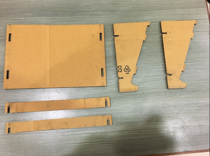
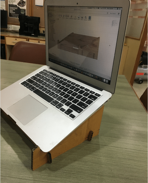
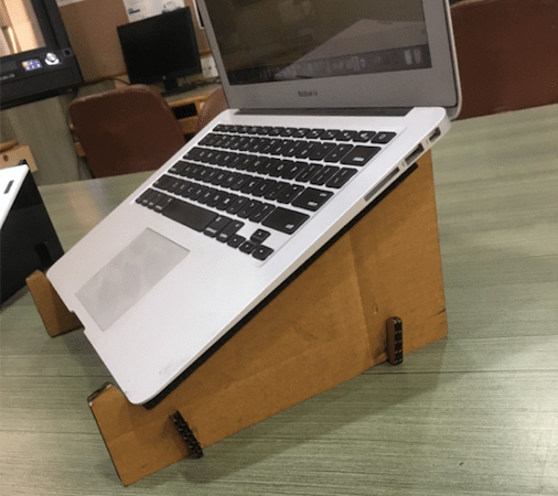
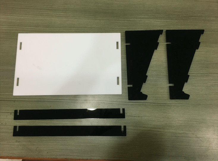
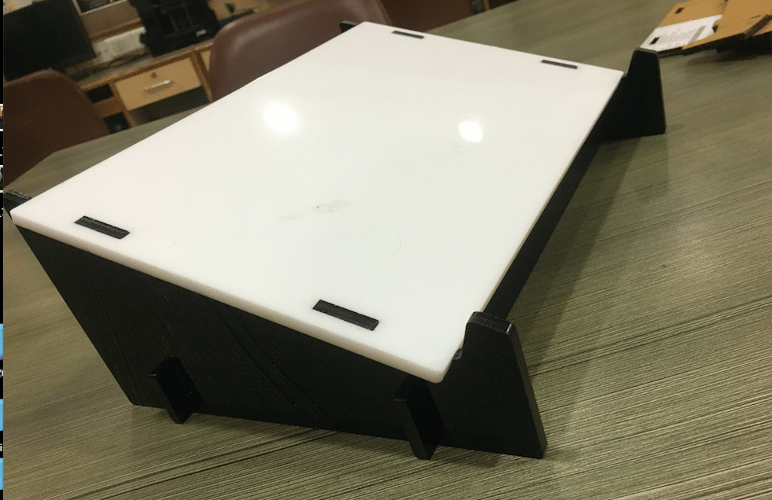
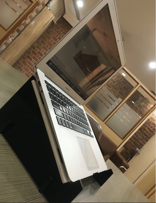
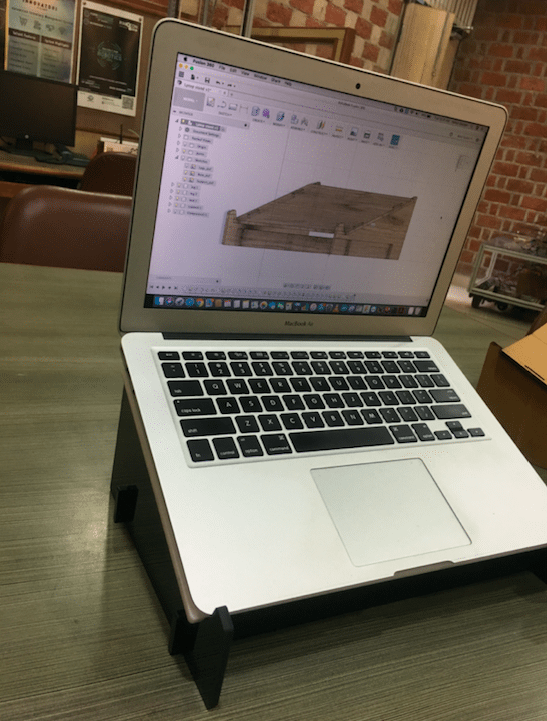
After the testing I started working with press fit construction. After fooling around many projects over the internet I decided to make a Laptop Stand on Fusion 360 for which I followed a Youtube video. This was my second project on Fusion 360 and I learned about new features of the Fusion like it was my first time I used combination command, I learned about making constraints, extrutions, Making a Sketch over a body, Mirroring, Applying fillets on all the edges, Subtracting surfaces, Exporting DXF files etc.
The project this time is completely parametric, I have defined 2 basic paramters which are the thickness of the material and the size of the laptop. Accordingly it'll change the shape along with all the press fit joints.
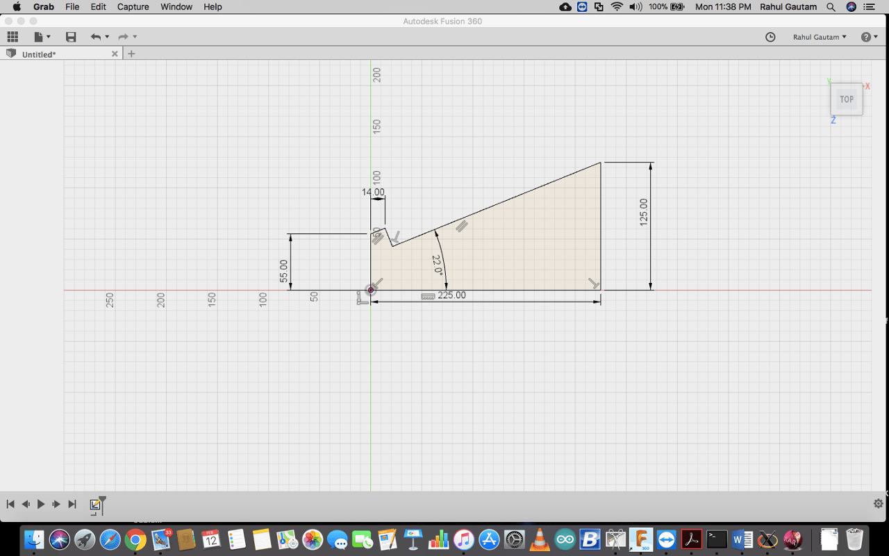
Final CAD Drawing
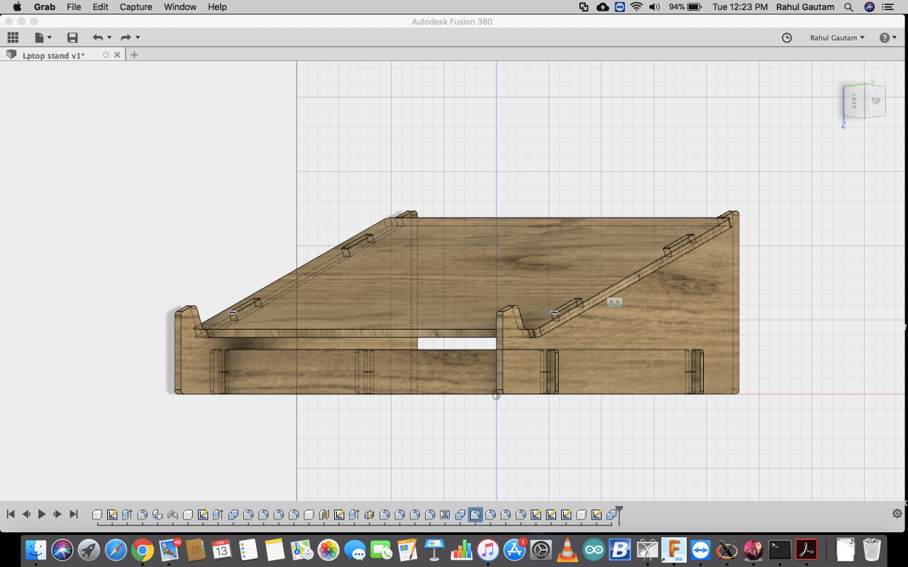
After this I exported the DXF files and let the LASER cutter do the rest.
Firstly, I tried to cut it on Cardboard. It was perfect.
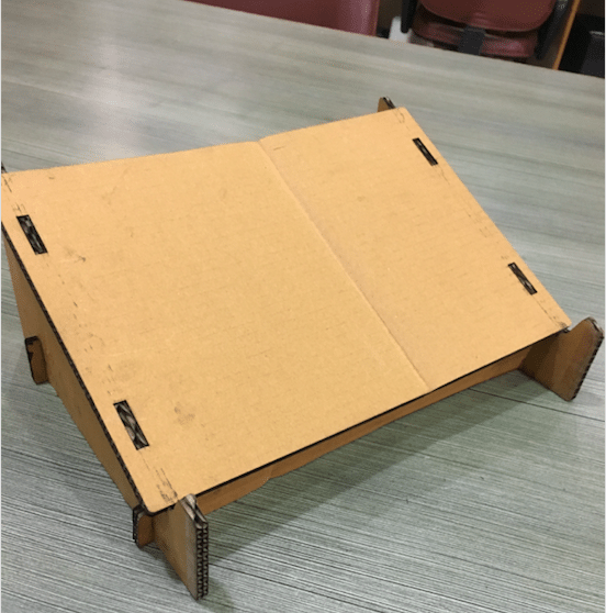
After successful trial with the cardboard, I decided to move ahead with Acrylic Sheet.
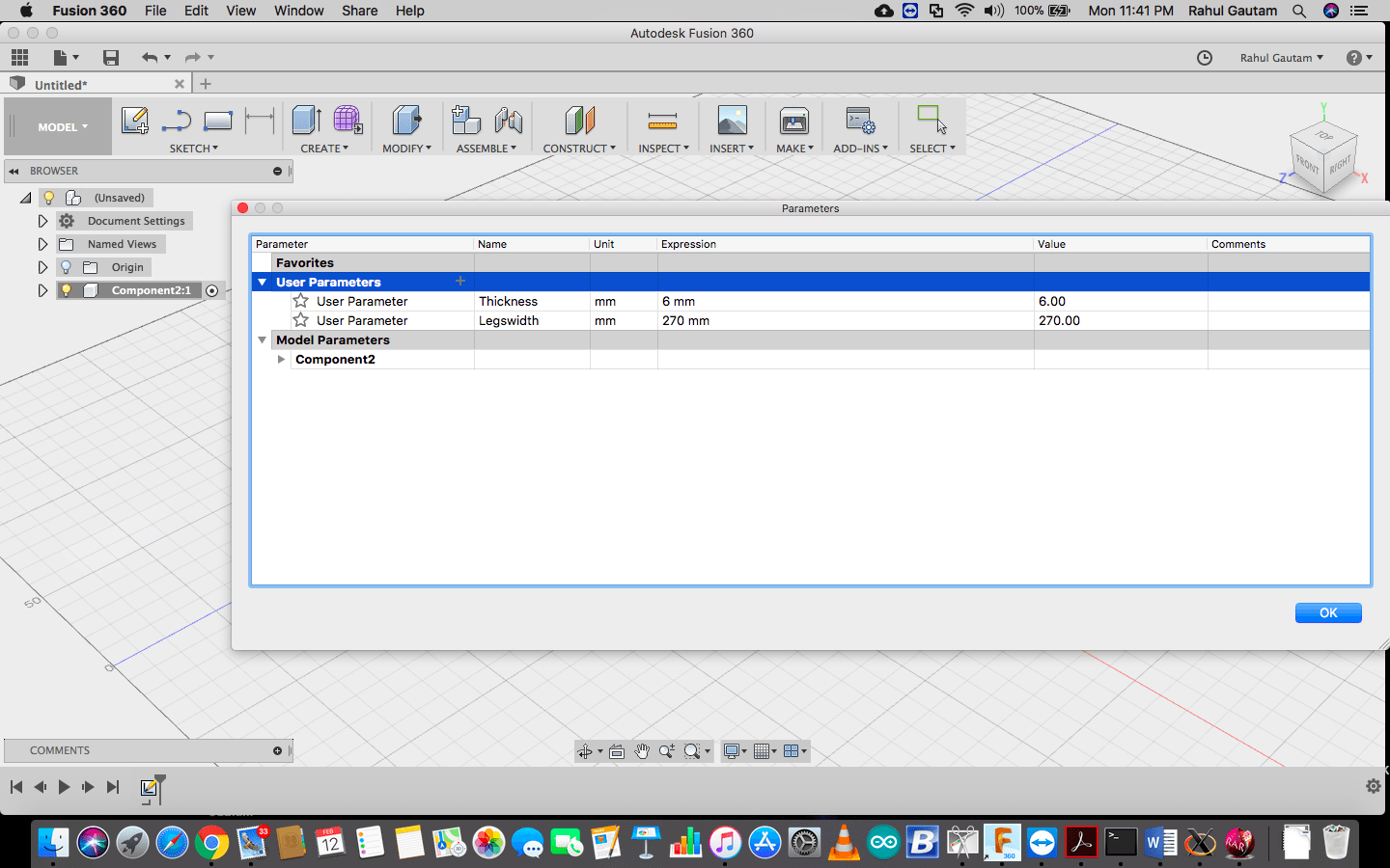
How to change parameters ?
Here I am sharing the steps to change the parameters of the laptop stand.
Go to Modify >> Change Parameter >> Change Parameters.
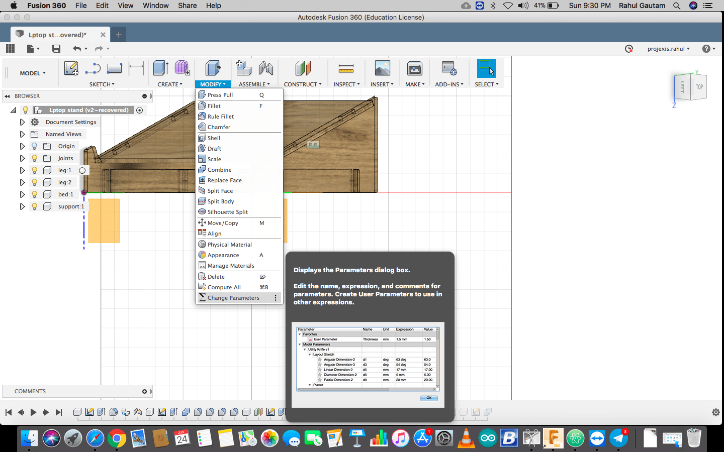
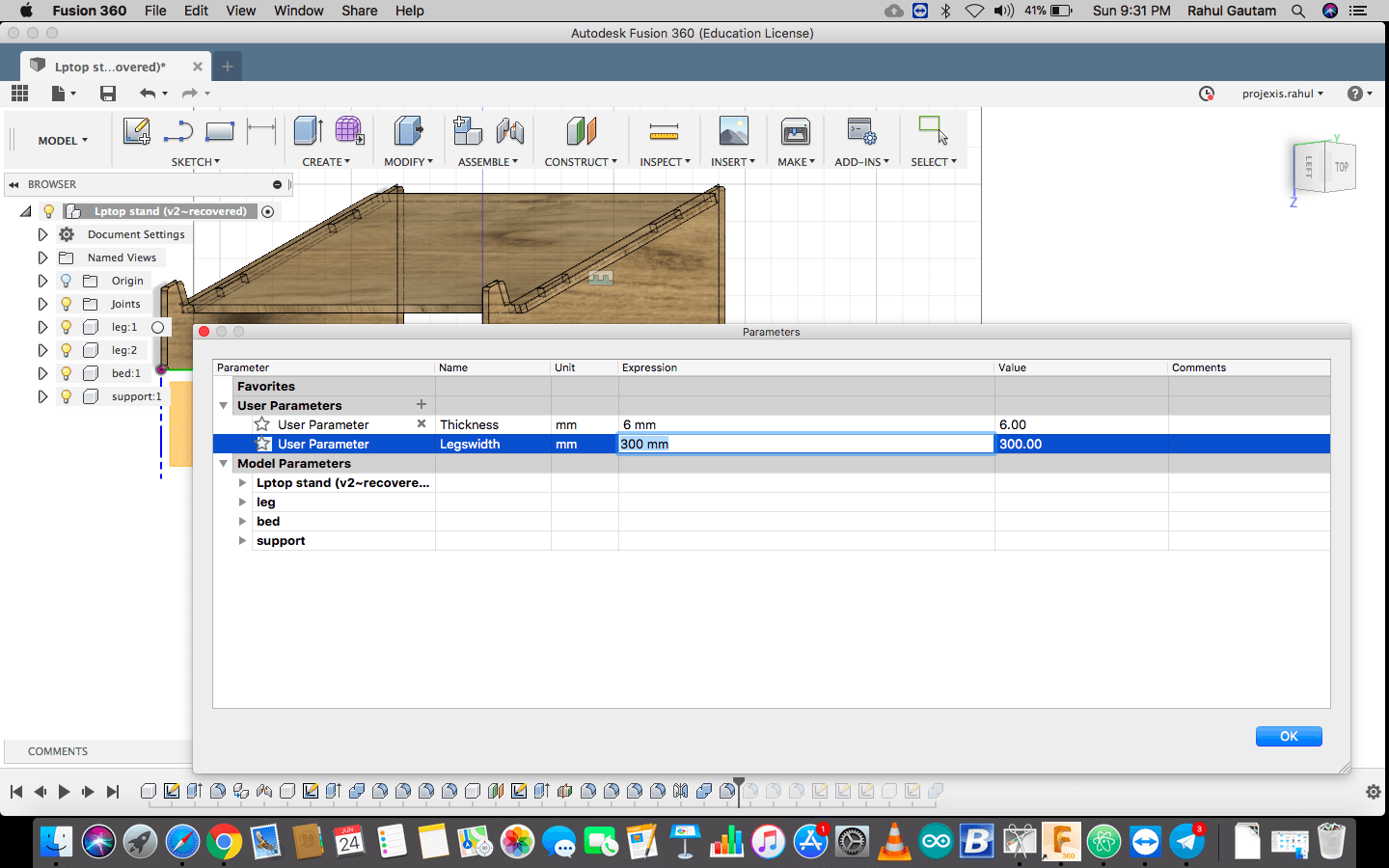
There are 2 parameters on which whole laptop stand is based, Thickness of material and width of legs ( Laptop width )
Download all Files Download Laptop Stand FilesMaking a Parametric Press Fit Construction Kit
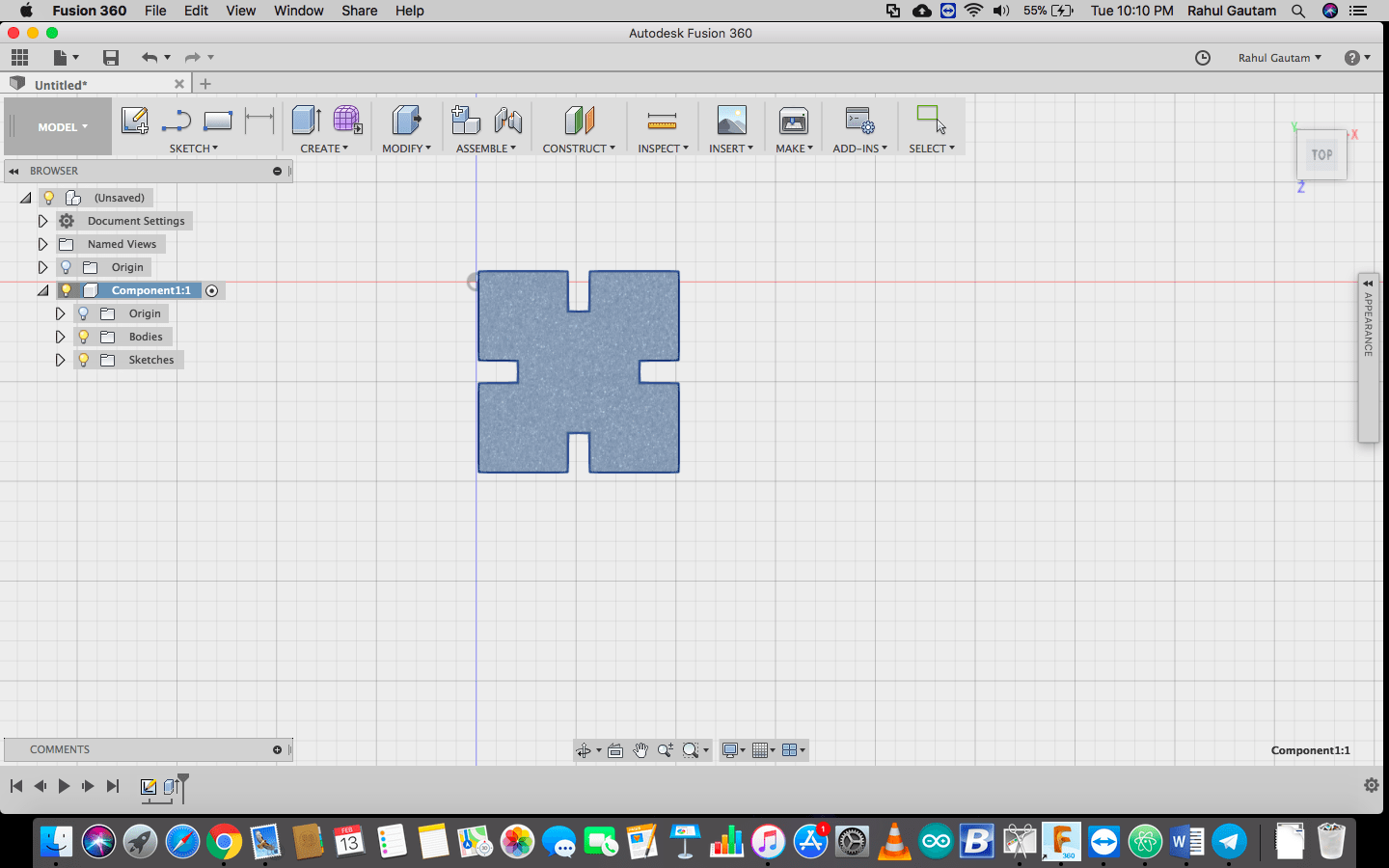
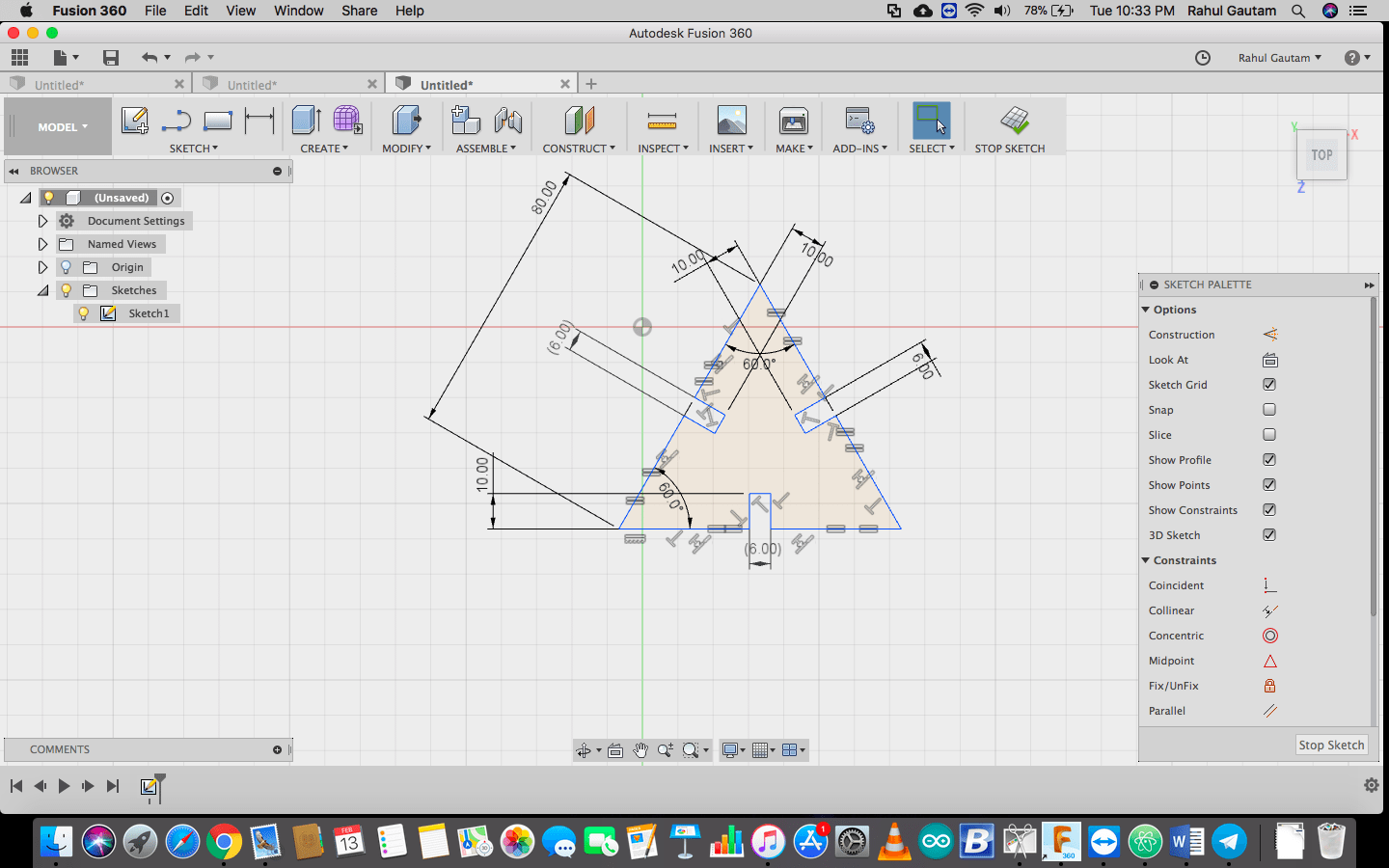
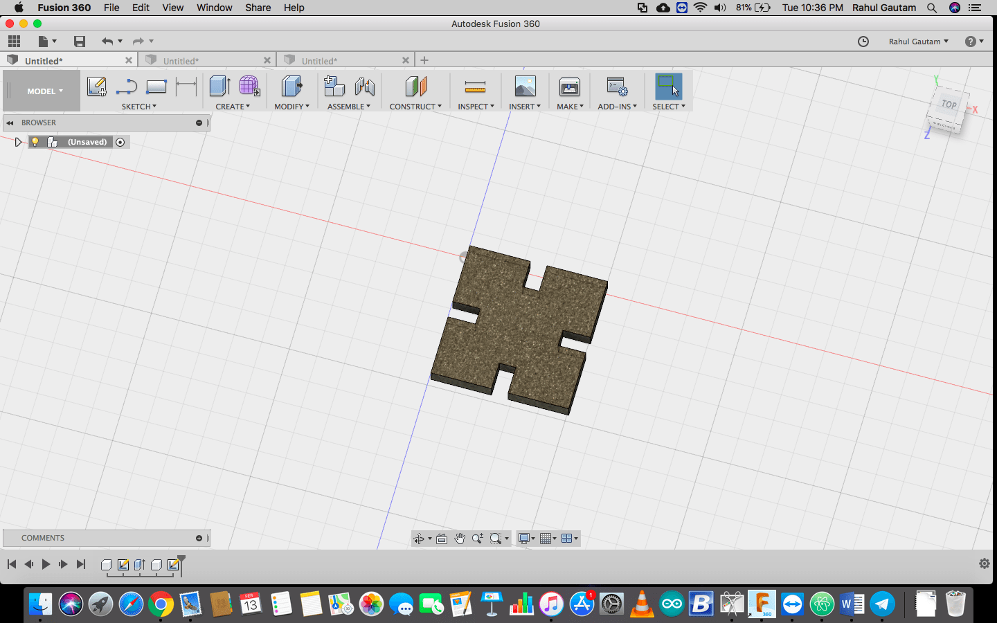
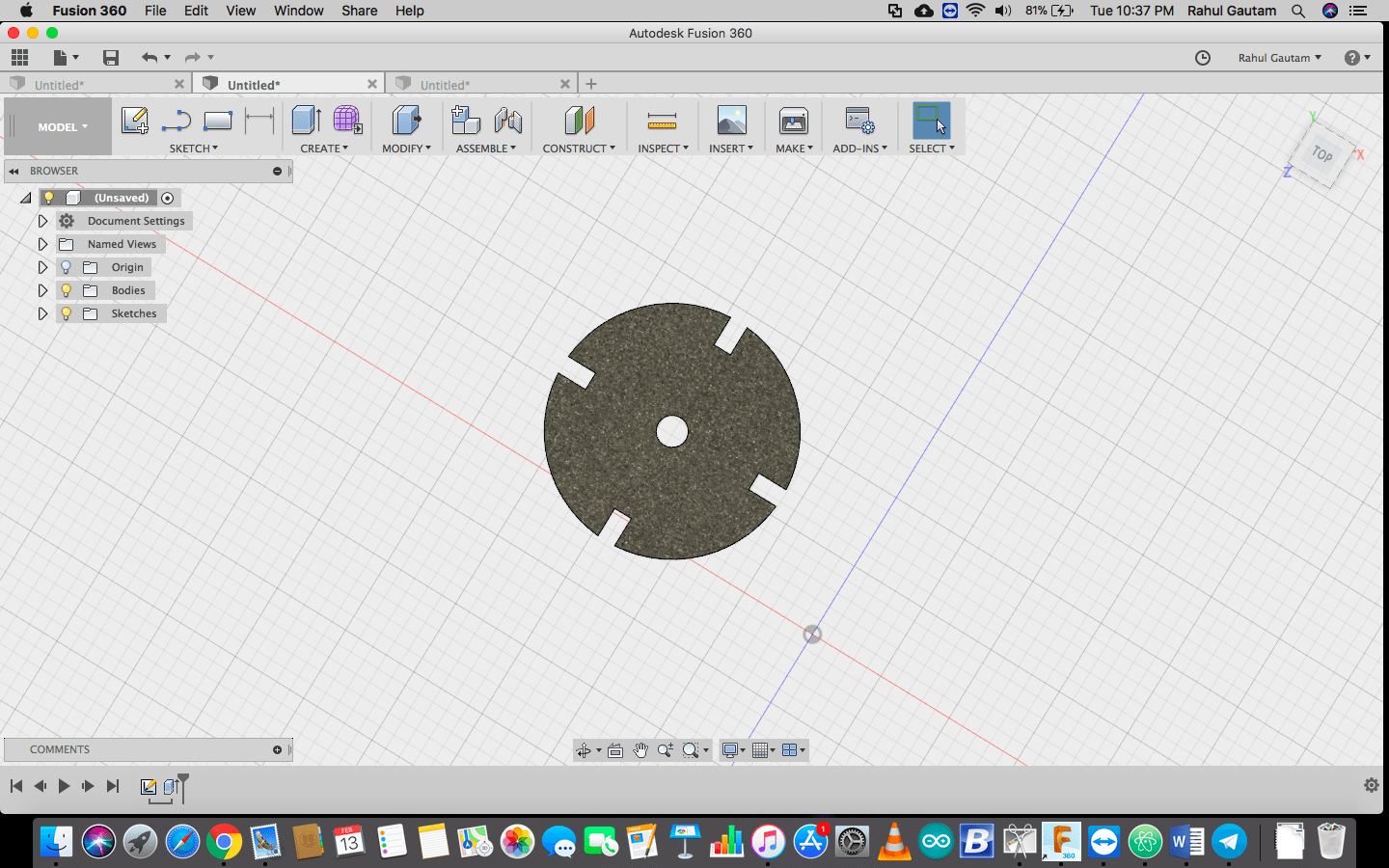
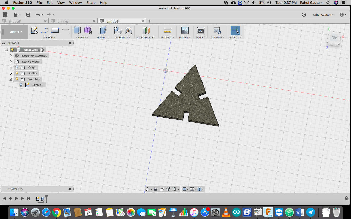
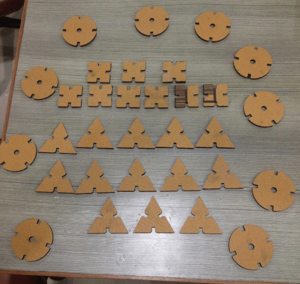
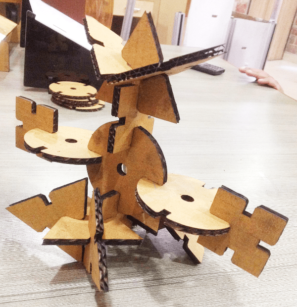
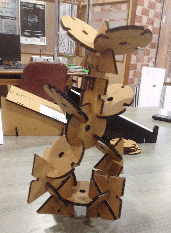
Well this category of this week's assignment was not very much clear to me...... I was a bit confused what to make ...... So after a lot of brain storming I ended up making basic shapes with some PRESS FIT arrangement so that they can be played with different configrations.
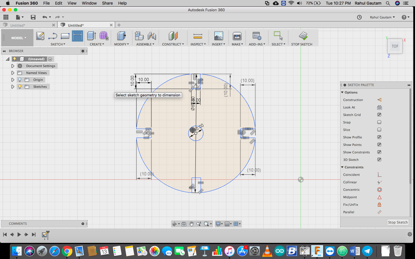
So I started with making a shape using the sketch menu in Fusion 360, then I played along with the tools, like trimming, making constraints, mirroring, extruding, different materials veiw etc.
How to change parameters ?
Go to the time line and over the sketch right click >> Edit Sketch
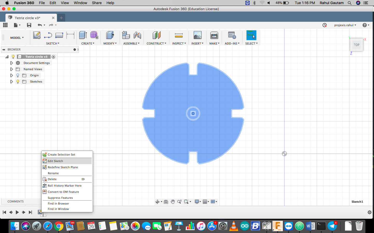
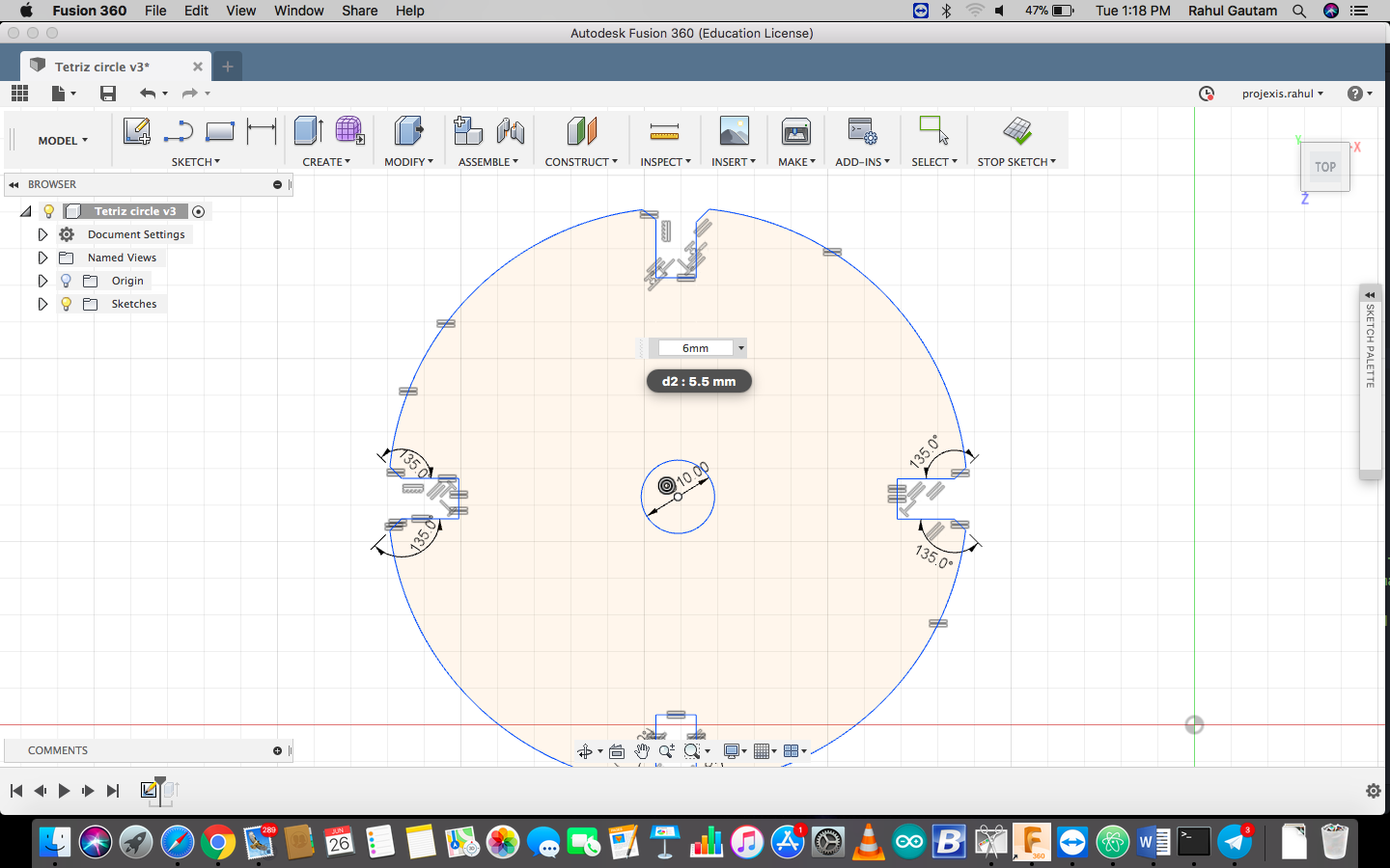
In the design it may noticed that the notch is having equality constraint, when we change the dimension of one notch from 5.5mm to 6mm all the notches width change, this is propagation and preserving design intent parametrically.
Experience while cutting
Overall exeperience with laser cutting was "Feeling of a kid fed with some candies". Well, I thought it would be like cutting an apple pie, but trust me it was not........ I did 3 iterations to get the final outcome. The power and speed combination I used was P:90 Speed : 40 . Actually , I have calculated the kerf accurately but since the base of Our LASER Cutter was not leveled I used to give multiple passes to get the final cutout. So for 2 passes kerf was increased so I changed the dimentions and then finally the outcome was good . I played along with a co student and made different things. I wish to have this machine at my home ........ My future kids can have dady made tetrix kit ..... plus their future dady can make stuff .......
Contact Me
I am happy to talk you through any projects or run live demos to see how they look like.