FABACADEMY
GARUDA
Welcome to my week Final Project 2
PROJECT GARUDA
Basically my project is Electric Skateboard due to some problems I changed my project to Remote controlled car {GARUDA}
Introduction to GARUDA (RC cars)
Cars and Trucks have been the fastest growing category of radio control in the past decade and rightly so. They are fast, exciting, and something everyone of all ages can take part in at their own level.
R/C land vehicles fit into five main interest categories Off Road Buggies, On Road Cars, Monster Trucks, Stadium Race Trucks, and Motorcycles. All of these vehicles can be found powered by electric motors and more recently some of the vehicles have been offered in glow and gas powered versions.
REASON
I just wanted to make it because if u want to bye in market they sell for dobble price so i tought to make it in our lab.
And this idea given by my instrctor so thanks to him.
PROCESSES INVOLVED IN PROJECT.
3D Designing and 3D Printing
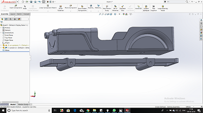
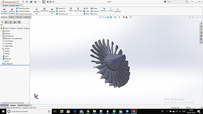
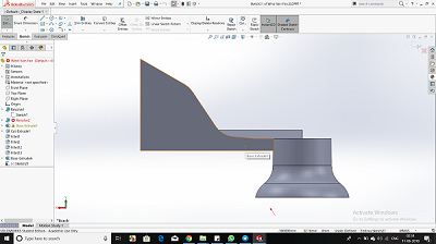
3D designing of Jeep, Propeller, Remote. I have used Software Solidworks for the same. I tried making a complete product while designing. Designing has helped me bring my ideas to reality, being from nond esign background it was hard to learn new softwares , specially when every software has its own shortcuts and features.
DESIGNING GARUDA (Jeep)
I am not from a Design background but due to my interest in designing and bring in small elements to increase the functionality of my design, i was able to do this.
3D printing of GARUDA(Jeep)
3d printing seems to be an easy process but it relies alot on your design and settings you do while creating gcode to g file. While I used makerbot print, i was able to learn to control infill, support and support strength by the end of my project.
Finnaly After a long wait of 48 hours I got all my parts in my hand and its feel good.
.jpg)
.jpg)
.jpg)
.jpg)
Download .sld file
Electronics
Electronics in this project plays a major role, starting from making an 2 Attiny 44 board for my project 1 for Transmitter and the other for Reciever.
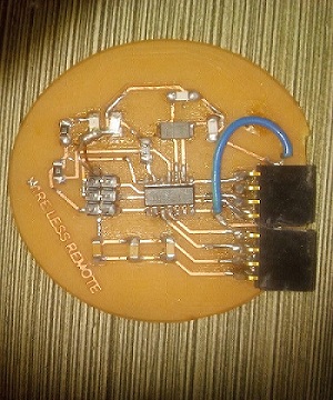
Design for Transmitter
So I have a Transmiting Bluetooth as a master and a joystick for moving my GARUDA (car) forward, right, left. there is no reverse in my car
so I designed a pcb given below.........
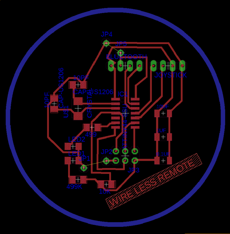
I exported my file in .png so that I can mill my board..
DESIGNING GARUDA (Jeep)
I am not from a Design background but due to my interest in designing and bring in small elements to increase the functionality of my design, i was able to do this.
3D printing of GARUDA(Jeep)
3d printing seems to be an easy process but it relies alot on your design and settings you do while creating gcode to g file. While I used makerbot print, i was able to learn to control infill, support and support strength by the end of my project.
Finnaly After a long wait of 48 hours I got all my parts in my hand and its feel good.
Download .sld file
Electronics
Electronics in this project plays a major role, starting from making an 2 Attiny 44 board for my project 1 for Transmitter and the other for Reciever.
Design for Transmitter
So I have a Transmiting Bluetooth as a master and a joystick for moving my GARUDA (car) forward, right, left. there is no reverse in my car
so I designed a pcb given below.........
I exported my file in .png so that I can mill my board..
Transmitter traces
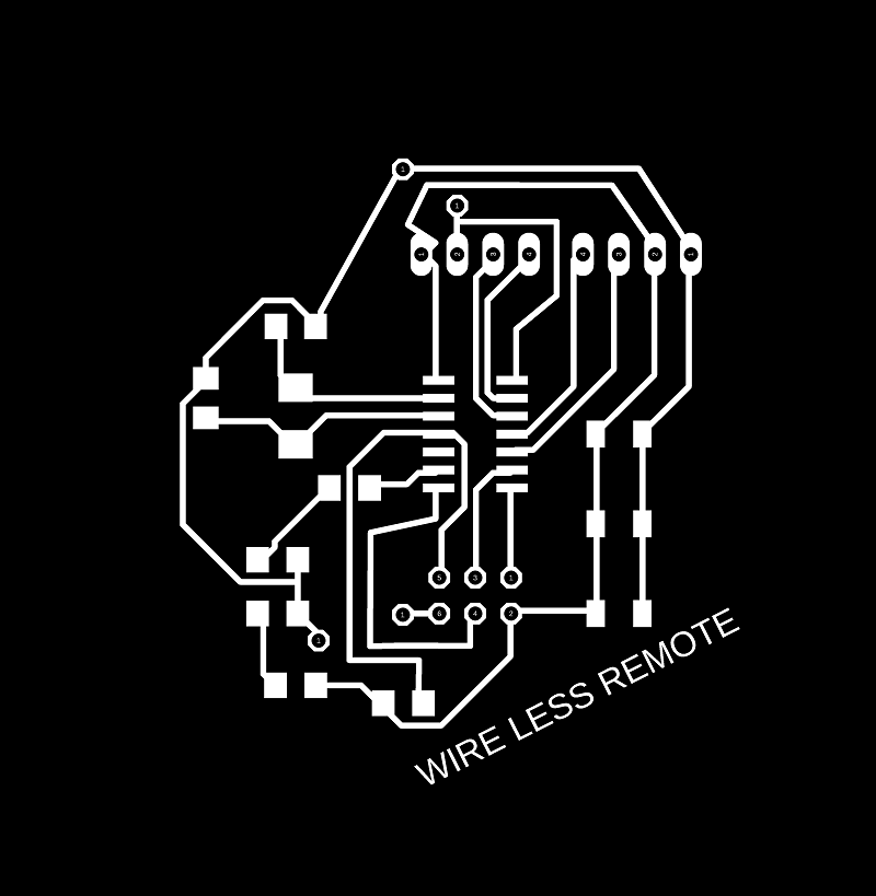 Transmitter outline

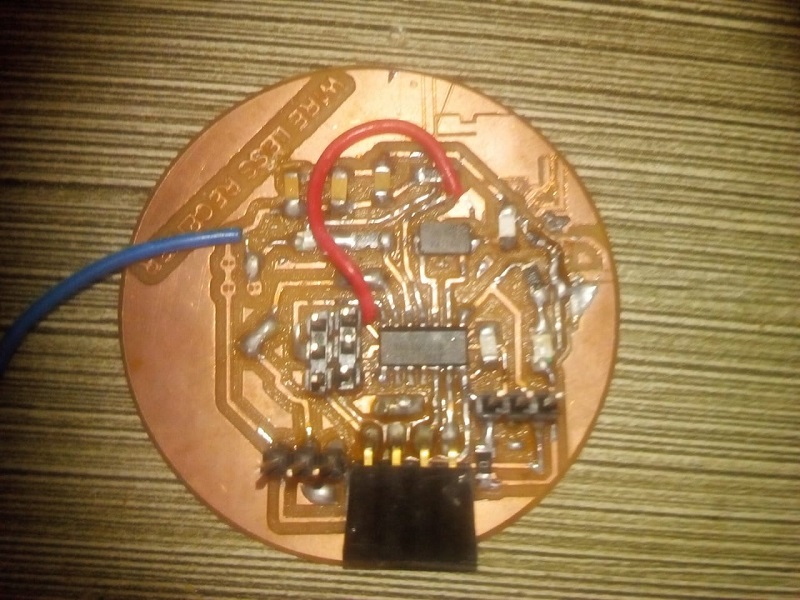
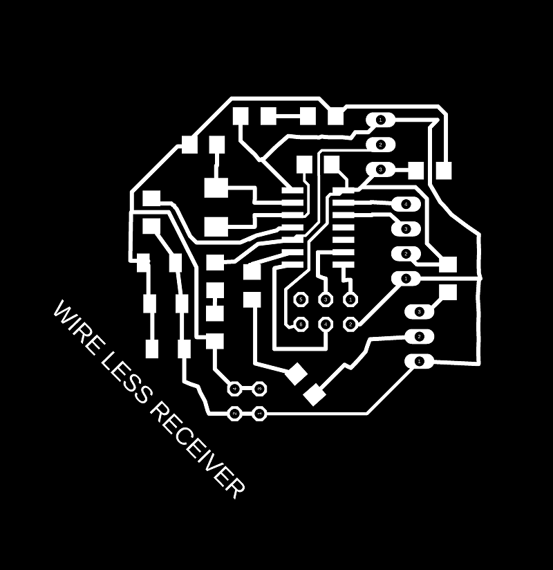
Design for Reciever
So I have a Recieving Bluetooth as a slave and a esc for rotating my bldc motor and also a servo motor for direction of GARUDA
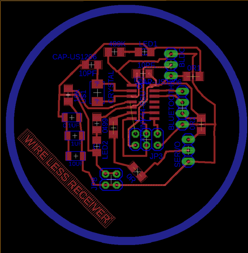
Receiver traces
 Receiver outline

Now Milling ............
Transmitter
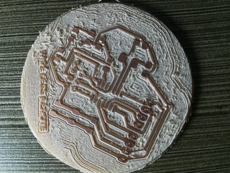
Receiver
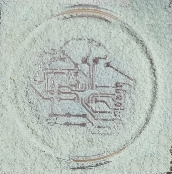
So to know more information of milling process click here
Download .png files
Now soldering.........
I brought all the components