FABACADEMY
Machine Design
Welcome to my week 16
Machine Design
Learning Outcomes:
Brief
In our team we are 4 people.
Division of Roles
Well .... this was a crucial step to ensure that the machine is made within time and operational ........ So we decided to divide the roles as per everybody's comfort and experience ....
So here's how we divided the roles :

1. TARIGOPPULA SAI ADIYA VYNATHEYA ----------> Mechanical Structure and design.

2. ABHINAV GARG ----------> Mechanical Structure and design.

3. RAHUL GAUTAM ----------> Electronics.

4. ASHISH SAWHNEY ----------> Jack of all.... but Majorly Documentation.
This weeks assignment was to make a machine which involes actuation, automation and mechanism ........
After a lots of brainstorming with the team ........ after bypassing lots of ideas which were not feasible in this time window we decided to make a POLOGRAPH well I was a noob in machine design but one of our group member was from mechanical design with a sound practical knowledge so it was a bit easy for me to digest POLOGRAPH well from my understanding point of veiw what I understood was its a 2D plotter but vertical well it sounded a bit wierd to me at first but after going through lot of internet pages about polographs I was suprized to see people doing wonders with this simple machine then I started working on the same machine I studied what all people have done and how they have done ..
So after all this we started to make somethings on a page Abhinav from our group ( The mechanical guy ), took the responsibilty to make a sketch of the machine here I am sharing his Sketch.....
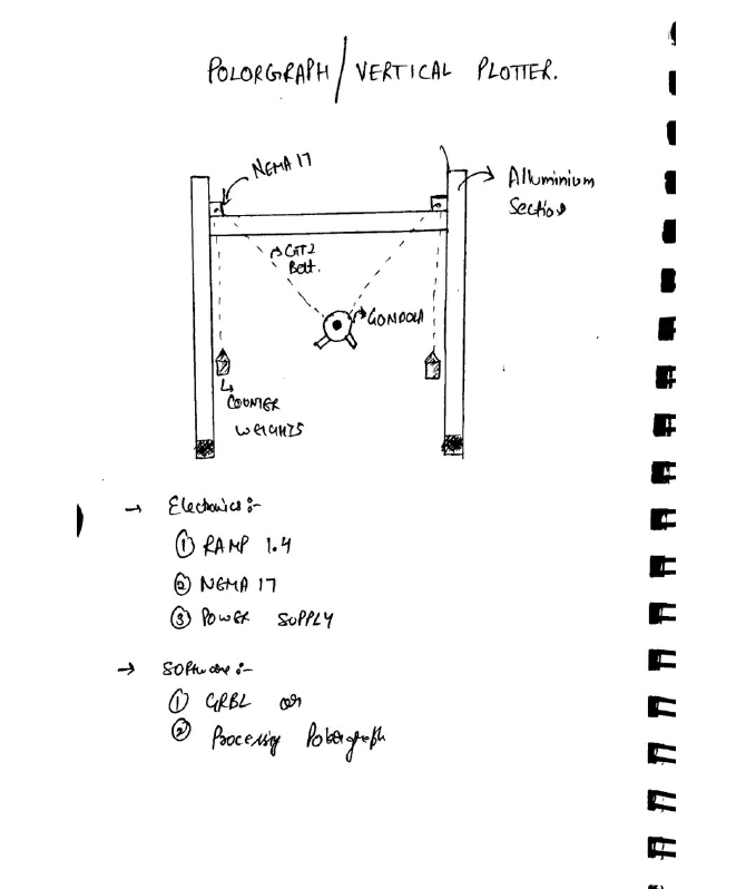
Well...... this is not just a sketch it was the outcome of 2 days of brain storming............
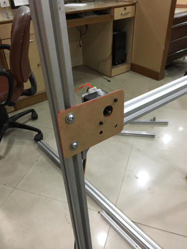
After the division of roles our group started working on the mechanical design first for the raw materials we used what was available in the lab we used some older projects which we dismanteled and then used them to make the sturcture of the machine Apart from than we made some mountings for the motor using LASER Cutter........
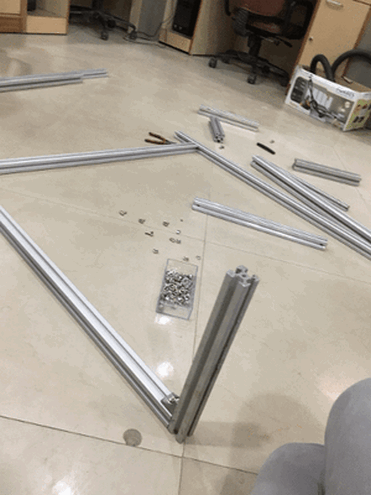
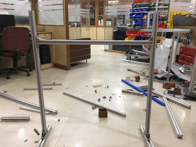
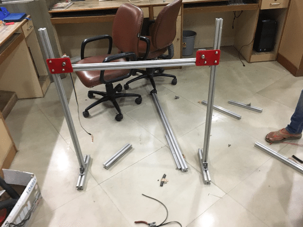
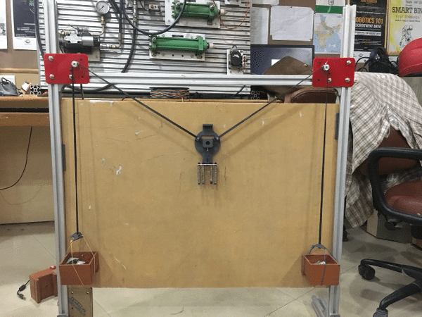
Here are few pics of the machine assembling....
working with fun..............
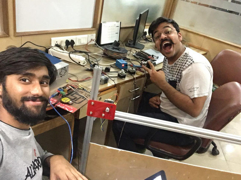
My personal contrubution in group project is testing {A4988} microstepping drivers and fixing all the machanical Structure..
There was a problem that the stepper motors are not working so after a lot of testing we got to know the stepper motor drivers are not working.
So I have started testing the motor drivers.
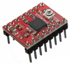
so we have 4 {A4988} microstepping driver.
I have started reading about A4988
overview: The A4988 is a microstepping driver for controlling bipolar stepper motors which has built-in translator for easy operation. This means that we can control the stepper motor with just 2 pins from our controller, or one for controlling the rotation direction and the other for controlling the steps.
The Driver provides five different step resolutions: full-step, haft-step, quarter-step, eight-step and sixteenth-step. Also, it has a potentiometer for adjusting the current output, over-temperature thermal shutdown and crossover-current protection.
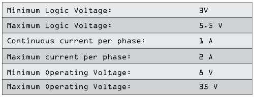
Its logic voltage is from 3 to 5.5 V and the maximum current per phase is 2A if good addition cooling is provided or 1A continuous current per phase without heat sink or cooling.
A4988 Stepper Driver Pinout
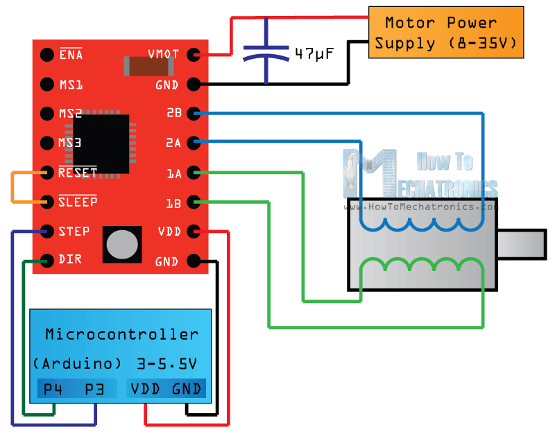
Circuit Schematics
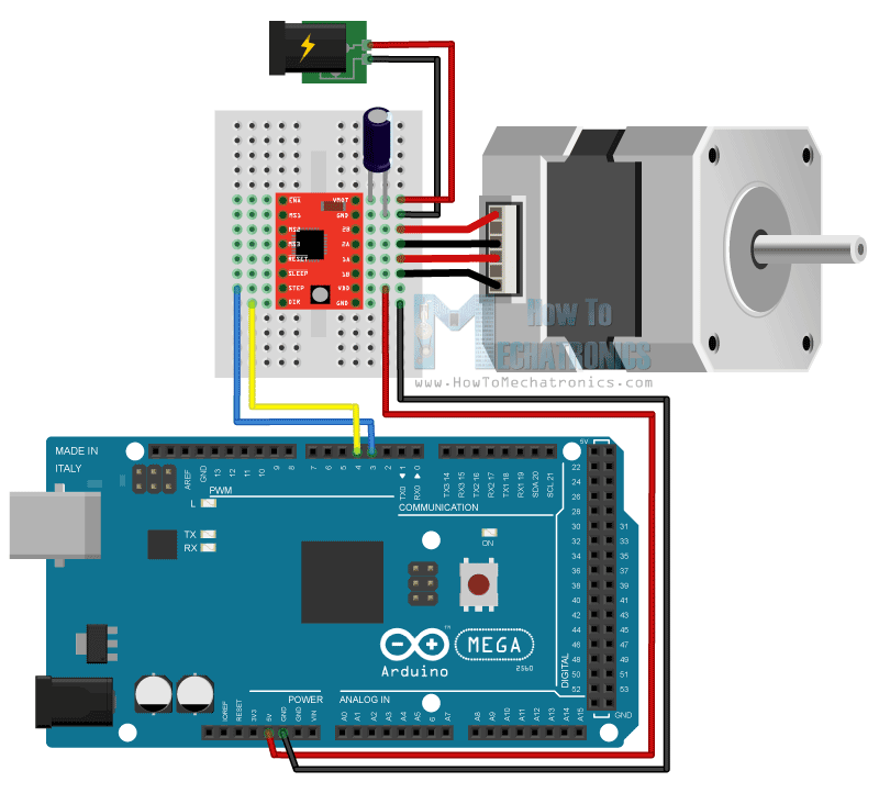
Components needed for this test
You can get the components from any of the sites below:
- Stepper Motor (NEMA17)……................... Amazon / Aliexpress
- A4988 Stepper Driver………….. Amazon /Aliexpress
- 12V 2A Adapter……………………...... Amazon /Aliexpress
- Power Jack…………………………… Amazon /Aliexpress
- Arduino Board…………………….. Amazon /Aliexpress
- Breadboard and Jump wires… Amazon /Aliexpress
 // defines pins numbers
const int stepPin = 3;
const int dirPin = 4;

void setup() {
  // Sets the two pins as Outputs
  pinMode(stepPin,OUTPUT);
  pinMode(dirPin,OUTPUT);
}
void loop() {
  digitalWrite(dirPin,HIGH); // Enables the motor to move in a particular direction
  // Makes 200 pulses for making one full cycle rotation
  for(int x = 0; x < 200; x++) {
    digitalWrite(stepPin,HIGH);
    delayMicroseconds(500);
    digitalWrite(stepPin,LOW);
    delayMicroseconds(500);
  }
  delay(1000); // One second delay

  digitalWrite(dirPin,LOW); //Changes the rotations direction
  // Makes 400 pulses for making two full cycle rotation
  for(int x = 0; x < 400; x++) {
    digitalWrite(stepPin,HIGH);
    delayMicroseconds(500);
    digitalWrite(stepPin,LOW);
    delayMicroseconds(500);
  }
  delay(1000);
}
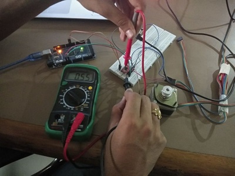
Current Limiting
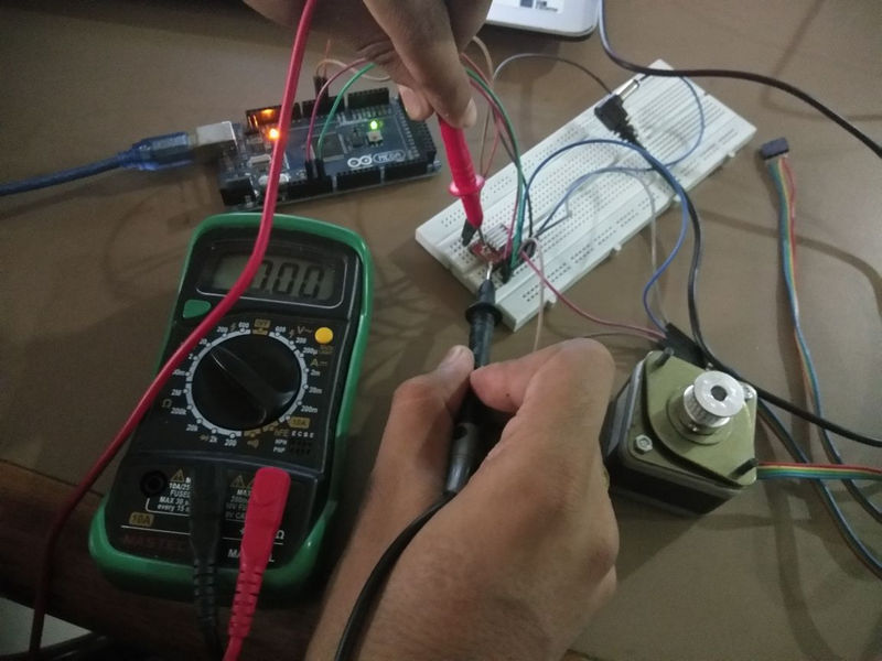
Before we connect the motor we should adjust the current limiting of the driver so that we are sure that the current is within the current limits of the motor. We can do that by adjusting the reference voltage using the potentiometer on the board and considering this equation: Current Limit = VRef x 2
So I have tested all the 4 motor drivers we had.
Driver 1
Driver 2
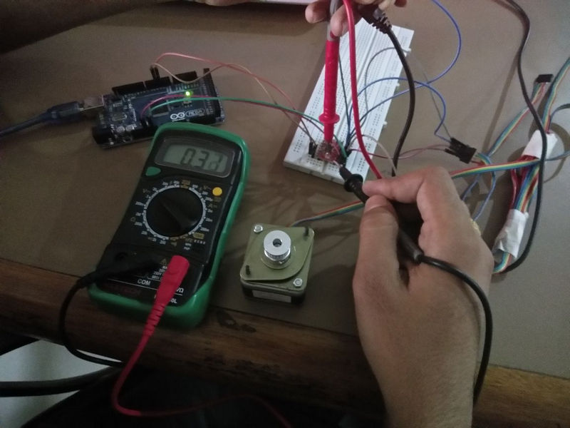
Driver 3
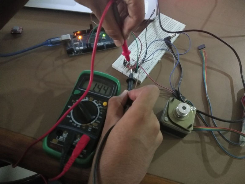
Driver 4
After connecting the drivers all those are heating alot..
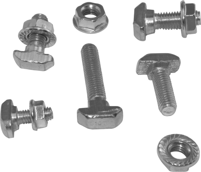
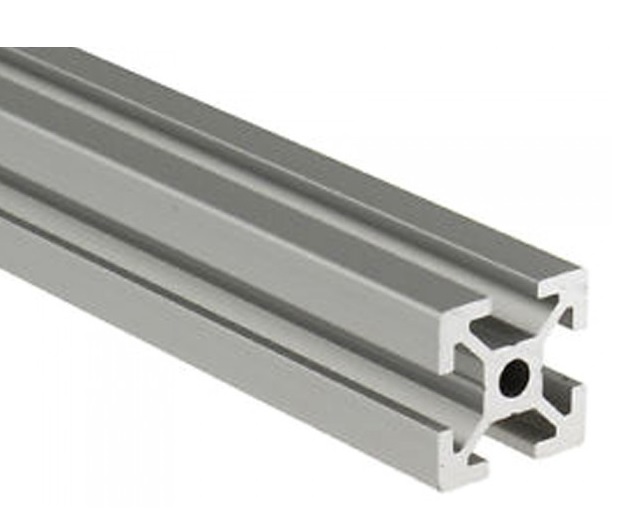
In mechanical structure -
Fixing the profies with nut and bolt.
And then we got new Motor driver.
Now our machine is working good.