FABACADEMY
Electronics Production
Welcome to my week 5
Electronics Production:
Learning Outcomes:
Learnt how to use Fab mod, MonoFab srm-20
Learning Soldering skills
Reading Schematics
Very interesting, this skill will take me long way
Brief
Electronics production is basically aimed at teaching about PCB's, how to design your own PCB's and types of PCB, Machining Process , PCB materials,components and assembly of components, use of fab module and programming AVR in system programmer, as said by Dr.Neil "program a programmer with the help of another programmer to program"
IDEAS THIS WEEK:
Am thinking of making the ISP so i followed the Brian's Broad.
ACHIEVEMENTS THIS WEEK:
Electronic Production:
Electronic Components
Got familiarised with diodes, Leds, Capacitors, Resistors, ICs, Zeners etc. by our instructor
Circuitry
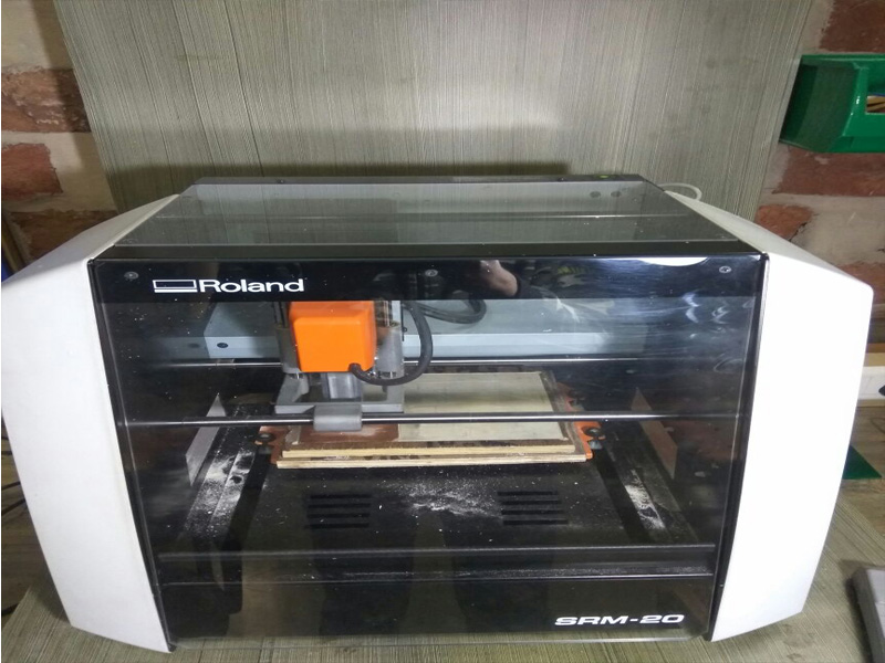
MonoFab srm-20 techniques
Populating of board
Soldering
Programming
Getting started with Electronics Production
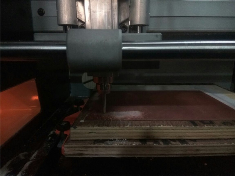
This weeks assignment was to get a hands on with electronic circuits and make your own ISP Programmer, which is supposed to be cool....... To get started with electronics production I started with reading all the content over the fabacademt schedule....... I went through all the boards and tried to understand them ....... and decided I'll make atleast two type of programmers for myself........ To get started I started with characterization of our machine i.e SRM 20. I downloaded the PNG file from the Fabacademy Schedule page .... then Using Fabmodules I made .RML file and finnaly it was milled...... It was a group assignament...... After the final milling the results were not so good ..... we realized the tool was not sharp from the end and it needs to be replaced ......
 Conclusion
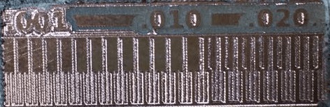
This test was performed to check the capability of the machine In this mill job test tracks from 1 Mils to 20 Mils were made and from the image it may be concluded that the machine was able to print 1 Mils also, but the track quality is not upto the mark, It was observed that the tracks above 12 Mils were perfect
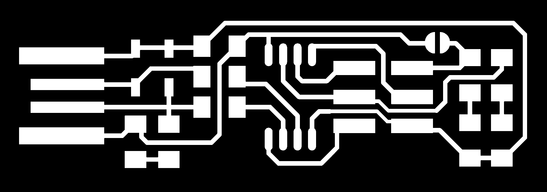
The one with a crystal (Neils Board)here
Source : 2018/Schedule here
So I download the design of Brian�s board
Traces (1000 dpi)

Outline Cutout (1000 dpi)

To mill my PCB in SRM-20
.RML File
For making .rml file I used Fabmodules.org
Here is the step by step guide to generate the .rml file
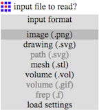
Step 1: Open Fabmodules.org and select the input format as Image(.png)
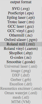
Step 2: Open the file (.png) and select the output as .rml
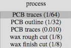
Step3: Now select the process as PCB Traces (1/64) as we are going to mill the traces for outline we'll use PCB Outline (1/32).
Step4: Now Select the machine which is in our case SRM 20
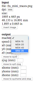
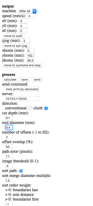
Step5: Now set the parameters as : and then click on save to download the file
Step6: Now after downloading the RML file, it time to mill out the board. Open V panel for SRM 20
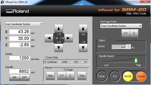
Step7: Now go to CUT button and select the downloaded RML File followed by clicking on Output
Precautions :
Make sure that the CLAD Board is fixed properly over the Machine bed otherwise during milling it may unstuck and it would be printing something else
Before giving a cutting command over the V panel make sure that the origin has been made according to the clad board and preevaluation of the space should be done before.
If you are allergic to dust you should wear a mask, learned this bad way I am allergic
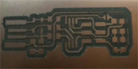
Now taking care of all the things, since our tool was custom modified so the statndard parameters which we gave were not enough to Mill out a proper PCB. So, We modified the parameters as : Cut depth was increased to 0.12mm which was earlier 0.1mm, apart from that tool diameter was also incresed from 0.35mm to 0.4mm. After setting the parameters the final milled PCB's were as :
so this is my final cut of board.
And then i gather my components. I started my soldering.
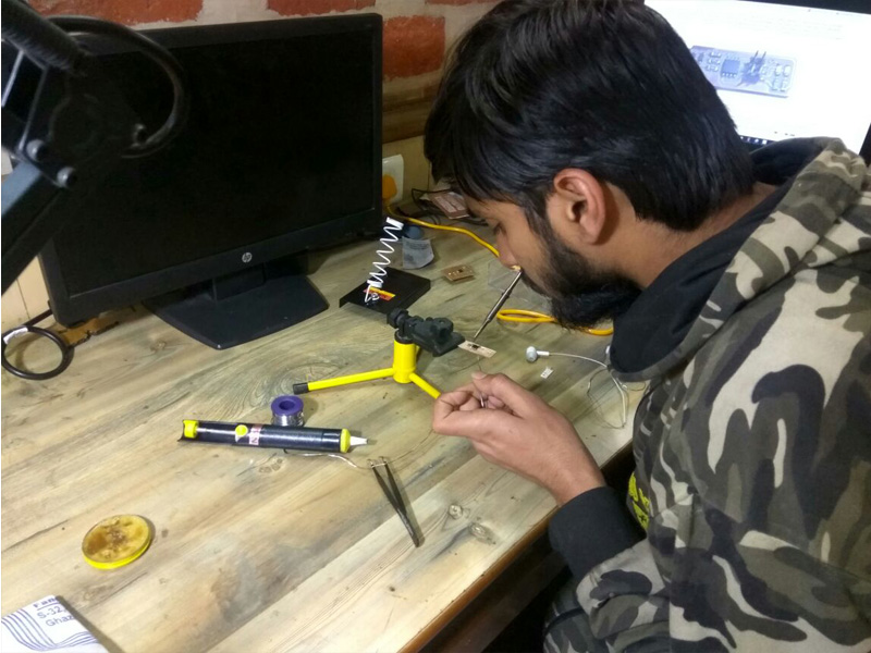
Finally I did it.
In this way I did this.
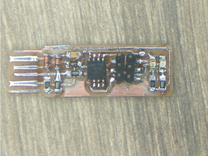
Now testing of my PCB.
Frist tested with multimeter


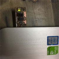
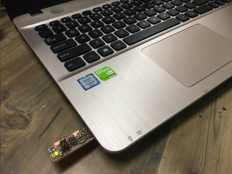
Second I directly pluged in my laptop.
so one of my friend told me that i have done the reverse soldering of leds so i desoldered the leds and resoldered the leds.
This looks prety good.......
Now its time to program
So first I tried it in my windows laptop but it dint worked so after some time I a long try I changed my mind set to use Ubuntu for programing.
I followed I Brian�s website.
Step one:)
Software Installation (highly recommended)
For Ubuntu and other Debian-based distributions, enter the following command, followed by your password when prompted:
sudo apt install avrdude gcc-avr avr-libc make
Step two:)
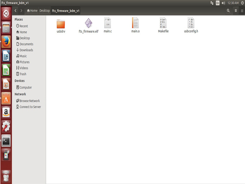
I downloaded this file (firmware source code) for programming.
Download the firmware source code
Step there:)
Run make.
This will build the hex file that will get programmed onto the ATtiny45. When the command completes, you should now have a file called fts_firmware.hex.
For this i have used sudo because without this I can't do program.
here for more info
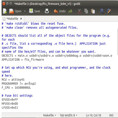
I updated the Makefile for the type of programmer Im going to use to program my board. The Makefile, by default, assumes that im going to use a programmer in the usbtiny family.
so I used this programer (Avrisp2)
Near the top of the file, I found the line that says:
PROGRAMMER ?= usbtiny
And I changed usbtiny to avrisp2
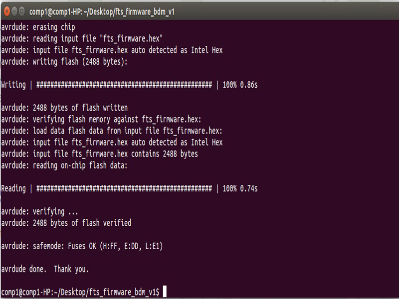
Run (sudo make flash). This will erase the target chip, and program its flash memory with the contents of the .hex file you built before. You should see several progress bars while avrdude erases, programs, and verifies the chip.
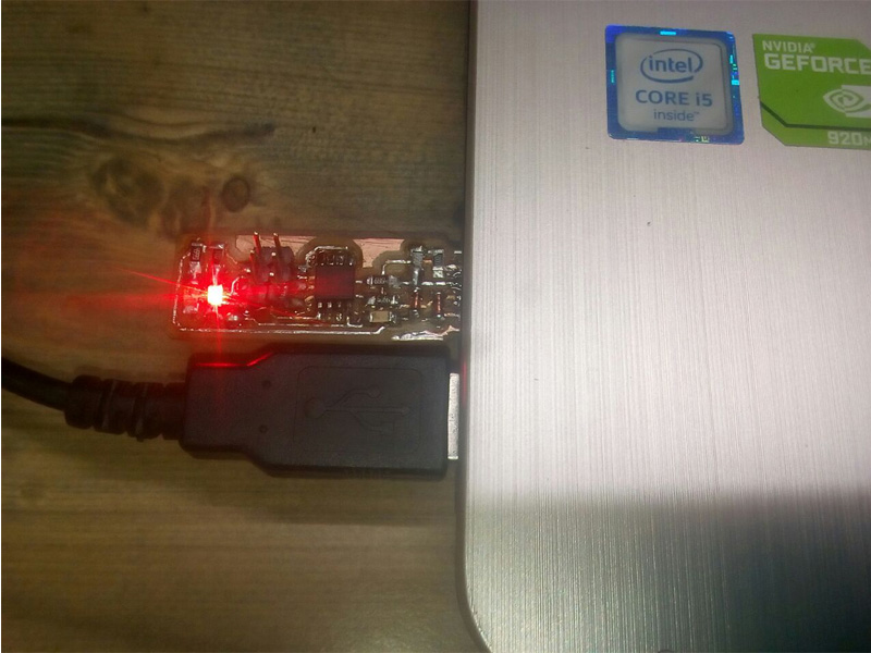
If you installed correctly the red LED lights up.
Connect the programmer to the ISP header on your board.
Run make flash. This will erase the target chip, and program its flash memory with the contents of the .hex file you built before.
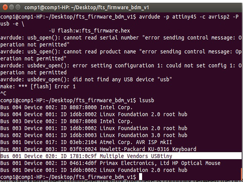
Now I will check to make sure that the USB on your board works, before blowing the fuse that will enable it as a programmer. I Unpluged my board from the USB port and disconnect the programmer, then pluged it back in to the USB. I Make sure the programmer you used to program your board is also disconnected from the computer.
I Typed lsusb in the terminal. which will list my USB devices.
I got to see this "Multiple Vendors USBtiny" device
It worked .............
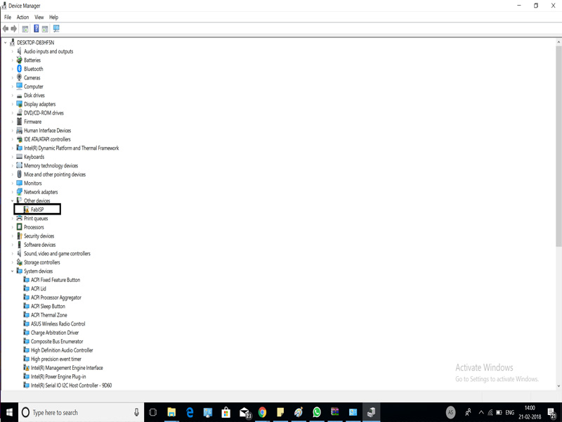
This looks like this in windows
Once you’ve succesfully programmed the flash memory, it’s time to set the configuration fuses. We’ll do this in stages:
First, set the fuses that control where the microcontroller gets its clock source from.
Run the make fuses command. This will set up all of the fuses except the one that disables the reset pin.
Brief
IDEAS THIS WEEK:
Am thinking of making the ISP so i followed the Brian's Broad.
Getting started with Electronics Production
This test was performed to check the capability of the machine In this mill job test tracks from 1 Mils to 20 Mils were made and from the image it may be concluded that the machine was able to print 1 Mils also, but the track quality is not upto the mark, It was observed that the tracks above 12 Mils were perfect
The one with a crystal (Neils Board)here Source : 2018/Schedule here So I download the design of Brian�s board
.RML File
For making .rml file I used Fabmodules.org
Here is the step by step guide to generate the .rml file
Step 1: Open Fabmodules.org and select the input format as Image(.png)
Step 2: Open the file (.png) and select the output as .rml
Step3: Now select the process as PCB Traces (1/64) as we are going to mill the traces for outline we'll use PCB Outline (1/32).
Step4: Now Select the machine which is in our case SRM 20
Step5: Now set the parameters as : and then click on save to download the file
Step6: Now after downloading the RML file, it time to mill out the board. Open V panel for SRM 20
Step7: Now go to CUT button and select the downloaded RML File followed by clicking on Output
Precautions :
I followed I Brian�s website.
Download the firmware source code
If you installed correctly the red LED lights up.
Connect the programmer to the ISP header on your board. Run make flash. This will erase the target chip, and program its flash memory with the contents of the .hex file you built before.
Once you’ve succesfully programmed the flash memory, it’s time to set the configuration fuses. We’ll do this in stages: First, set the fuses that control where the microcontroller gets its clock source from. Run the make fuses command. This will set up all of the fuses except the one that disables the reset pin.