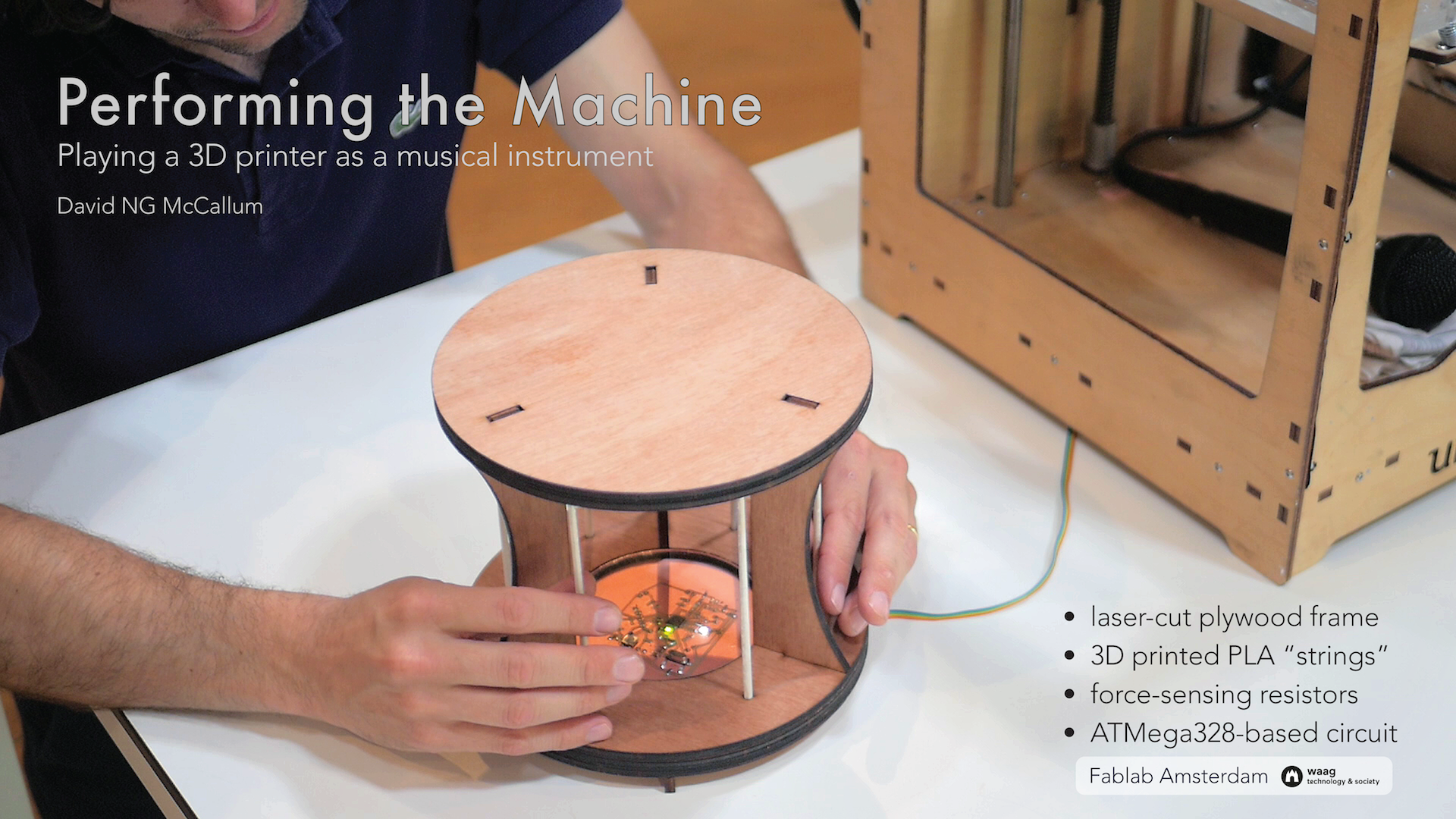
Final project: Performing the Machine

Except where otherwise stated, this work is licensed under a Creative Commons Attribution-NonCommercial 4.0 International License.
Project description
The Harp plays a 3D printer as a musical instrument. The interface has six rods, which when stroked cause the 3D printer to move its print head in six unique expressions. The force of the stroke controls the speed—and so the pitch—of the expression.
Each expression comes from the gcode used to print each of the rods, so the instrument is in effect performing elements of its own construction. The frame is designed to look similar to the printer that is being used, an Ultimaker Original.
Design files and code
- Frame model (Autodesk Fusion 360)
- DXF cut files for the plywood frame
- STL for 3D printing rod
- Electronics schematic and board layout (Autodesk Eagle)
- PCB milling files
- Microcontroller code (Arduino)
Production Processes
- 3D CAD: frame and rods designed in Fusion 360
- 2.5D CAD: Frame designed using 2D parts
- Additive production: rods 3D printed
- Subtractive production: plywood frame cut with a laser cutter
- Electronics: ATMega328-based circuit produced on a CNC milling machine, using force-sensing-resistors as input with a token LED as output, and establishing a serial connection to an Ultimaker.
Bom
About €10 worth of plywood, a few cents worth of PLA, and these electronics (plus 6 force-sensing resistors):
Part      Value            Device               Package       Description                                                                   MF    MPN            OC_FARNELL OC_NEWARK SUPPLIER TOLERANCE VALUE VOLTAGERATING
C1        2.2µF            0612ZC225MAT2A       CAPC3216X178N Capacitor 1206                                                                      0612ZC225MAT2A -          12N3209   AVX      ±20%      2.2µF 10V
C2        2.2µF            0612ZC225MAT2A       CAPC3216X178N Capacitor 1206                                                                      0612ZC225MAT2A -          12N3209   AVX      ±20%      2.2µF 10V
C3        10uF             CAP1206              1206          Capacitor
C4        1uF              CAP1206              1206          Capacitor
C5        100nF            CAP1206              1206          Capacitor
C6        100nF            CAP1206              1206          Capacitor
CRYSTAL   16Mhz            CSM-7X-DU            CSM-7X-DU     SMD CRYSTAL                                                                                        unknown    unknown
J1        TERM-1X02-FABLAB TERM-1X02-FABLAB     ED555DS-2DS   3.5mm terminal block, 2 positions ED555-2DS as found in the fablab inventory.
J2        TERM-1X02-FABLAB TERM-1X02-FABLAB     ED555DS-2DS   3.5mm terminal block, 2 positions ED555-2DS as found in the fablab inventory.
J3        TERM-1X02-FABLAB TERM-1X02-FABLAB     ED555DS-2DS   3.5mm terminal block, 2 positions ED555-2DS as found in the fablab inventory.
J4        TERM-1X02-FABLAB TERM-1X02-FABLAB     ED555DS-2DS   3.5mm terminal block, 2 positions ED555-2DS as found in the fablab inventory.
J5        TERM-1X02-FABLAB TERM-1X02-FABLAB     ED555DS-2DS   3.5mm terminal block, 2 positions ED555-2DS as found in the fablab inventory.
J6        TERM-1X02-FABLAB TERM-1X02-FABLAB     ED555DS-2DS   3.5mm terminal block, 2 positions ED555-2DS as found in the fablab inventory.
JP1                        PINHD-1X06_2.54      1X06          PIN HEADER
LED_GREEN LEDFAB1206       LEDFAB1206           LED1206FAB    LED
MICRO     ATMEGA328P-AU    ATMEGA48/88/168-AU   TQFP32-08
POWER     22-23-2021       22-23-2021           22-23-2021    .100" (2.54mm) Center Header - 2 Pin                                          MOLEX 22-23-2021     1462926    25C3832
R1        ZERO             RES-US1206FAB        R1206FAB      Resistor (US Symbol)
R2        499              RESISTOR1206         1206          Resistor
R3        ZERO             RES-US1206FAB        R1206FAB      Resistor (US Symbol)
R4        FSR              RES-US1206FAB        R1206FAB      Resistor (US Symbol)
R5        FSR              RES-US1206FAB        R1206FAB      Resistor (US Symbol)
R6        FSR              RES-US1206FAB        R1206FAB      Resistor (US Symbol)
R7        FSR              RES-US1206FAB        R1206FAB      Resistor (US Symbol)
R8        FSR              RES-US1206FAB        R1206FAB      Resistor (US Symbol)
R9        FSR              RES-US1206FAB        R1206FAB      Resistor (US Symbol)
R10                        RES-US1206FAB        R1206FAB      Resistor (US Symbol)
R11       ZERO             RES-US1206FAB        R1206FAB      Resistor (US Symbol)
R12       10K              RES-US1206FAB        R1206FAB      Resistor (US Symbol)
R13       ZERO             RES-US1206FAB        R1206FAB      Resistor (US Symbol)
R14       ZERO             RES-US1206FAB        R1206FAB      Resistor (US Symbol)
R15       499              RES-US1206FAB        R1206FAB      Resistor (US Symbol)
R16       ZERO             RES-US1206FAB        R1206FAB      Resistor (US Symbol)
R17       ZERO             RES-US1206FAB        R1206FAB      Resistor (US Symbol)
R18       ZERO             RES-US1206FAB        R1206FAB      Resistor (US Symbol)
R19       ZERO             RES-US1206FAB        R1206FAB      Resistor (US Symbol)
R20       ZERO             RES-US1206FAB        R1206FAB      Resistor (US Symbol)
R21       ZERO             RES-US1206FAB        R1206FAB      Resistor (US Symbol)
R22       ZERO             RES-US1206FAB        R1206FAB      Resistor (US Symbol)
R23       ZERO             RES-US1206FAB        R1206FAB      Resistor (US Symbol)
R24       ZERO             RES-US1206FAB        R1206FAB      Resistor (US Symbol)
R25       ZERO             RES-US1206FAB        R1206FAB      Resistor (US Symbol)
SWITCH                     6MM_SWITCH6MM_SWITCH 6MM_SWITCH    OMRON SWITCH
U$2       AVRISPSMD        AVRISPSMD            2X03SMD
U$3       LEDFAB1206       LEDFAB1206           LED1206FAB    LED
U$4       YELLOW           LEDFAB1206           LED1206FAB    LED
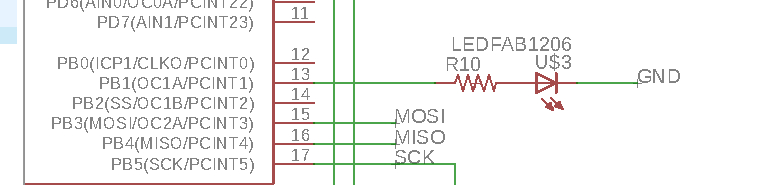
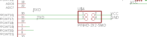
Here's how everything connects:
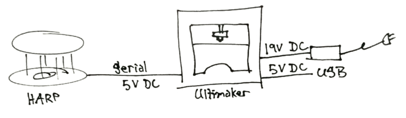
You might be wondering, "why does the ultimaker need both 19V DC and 5V DC? Shouldn't it be able to power its arduino from the 19V?" I wondered that too, until I stopped wondering and moved on to other problems to solve.
What works, what doesn't
Everything works. Except… The Harp has no flow control, and so will occasionally flood the printer's buffer and cause it to move erractically, this requires patience and a reset.
What I would work on in the next iteration
The performance behaviour needs finessing. I settled for something that worked, but not what I envisioned. The Harp has no aftertouch control after the expression has been triggered, this makes it much more like a drum than a violin.
The physical form is functional, but could benefit from an aesthetic reconsideration. The general form is boxy and without an evocative sense. Is a ring really the best construction? Consider something like the Kora, with the strings arranged in a V. I would also like to consider adornment in aspects such as engraving on the wood, and patterns in the PCB. The PCB should also be more visually balanced in its component placement.
The rods themselves have too much friction for a smooth sliding action. I should explore other materials, surface texture, raking angle.
The instrument has no indication of the expression of any of the rods. A piano goes higher in pitch from left to right, a guitar has a similar orientation and the feel and sight of the strings. The Harp has no intuitive or learnable indication of how expressions differ from each other.
All of the cable connections have polarity that is not enforced in the connectors, meaning that it is very easy to plug things in the wrong way. And the reset button should be on the underside of the board!
The Harp was designed for a printer where we have direct access to the serial pins of the PCB. Ideally, it would use a USB connection that would allow it to plug into any printer. This would probably involve using the v-usb library to have the harp function as a USB host.
It could benefit from either an acoustic resonator or a contact microphone with an amplifier and speaker. FOR LOUDNESS! This project may also become quickly obsolete, as newer printers are becoming much quieter. Maybe this can be compensated for with a contact microphone, maybe it's not worth it.
Future explorations: what about all the other CNC machines? Laser? Milling? There's so much to explore.
Final project log
This log is written in reverse chronological order. If you want to know how it started, scroll to the bottom and work your way upwards.
2018-06-17
The printer kept having erratic behaviour. Sometimes it would play the sequence, and sometimes it would just travel the length of an axis until it hit an endstop, and it wasn't always the same axis. After some thinking I suspected that, because I was doing no flow control, the buffer was being overrun. So I cut the gcode snippets down, and found that 7 lines seemed to be enough to have it work without having the strange behaviour. So now it looks like:
const float rod4[][3] = {
{9000,100.011,96.604},
{1200,100.583,96.394},
{1200,101.154,96.243},
{1200,101.742,96.145},
{1200,102.349,96.102},
{1200,102.946,96.117},
{5400,102.939,96.216}
};
One unfortunate behaviour is that at the beginning of each expression, the printer head has to travel to the first location from wherever it is. I knew this would be a problem. Future versions should list the expressions is relative coordinates, not absolute, so the printer can do the expression from wherever it is. The code would then have to keep track of the printer head's location, adjusting for when it gets too close to the edges.
But you know what? It's done for now.
2018-06-16
When trying to walk the gcode information, I was getting strange numbers when using sizeof() on the gcode array. I discovered that sizeof() lists the number of bytes in an array, not the number of entries. So, since each number is a float, which is 4 bytes, and each line of gcode has 3 entries, then I can get the number of lines of gcode by doing sizeof() / 3 / 4. Tada! It now works.
Uh oh, I ran out of memory with the gcode. Time to explore progmem?
I looked into progmem for array decided to prune down my variables instead. I got it below %100 and then go this warning on compile:
Sketch uses 6554 bytes (20%) of program storage space. Maximum is 32256 bytes.
Global variables use 2016 bytes (98%) of dynamic memory, leaving 32 bytes for local variables. Maximum is 2048 bytes.
Low memory available, stability problems may occur.
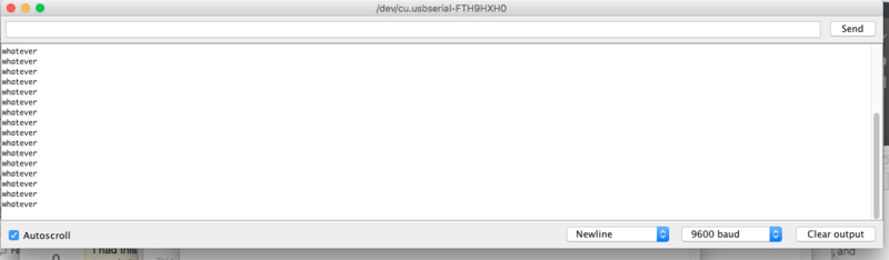
And you know what? Problems occurred. … Actually, when I copied and pasted the code, my HTML editor, Brackets, stopped reading the file, that's how weird the content was.
The garbage characters are weird enough, but there is a repeating "G1 X50 Y50" that shows that the arduino is rebooting. I'll trim the variables down a little further and see what happens.
2018-06-15
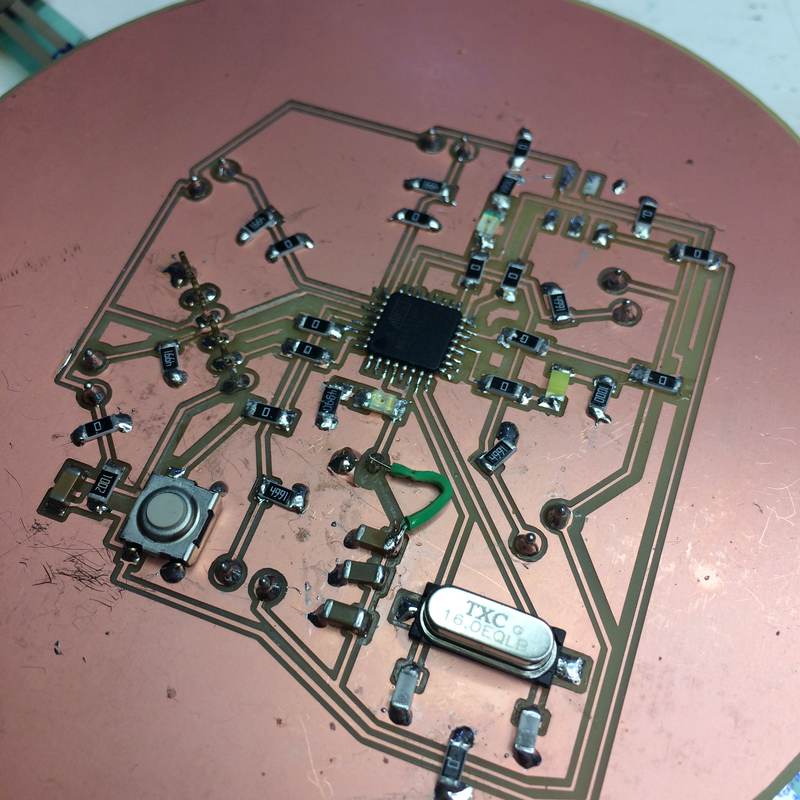
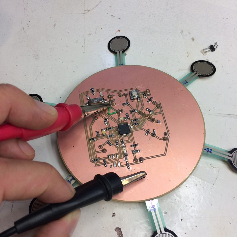
I moved the 6-pin FTDI and 2-pin power headers to the underside of the board. The FTDI moved fine, but the VCC trace for the power header was torn off the board. The connection was still good, but Emma suggested replacing it with a wire, so as not to cause any uncertainties about its connection. Here is the loose trace, the connecting wire, and testing with the power supply to make sure the connections worked. The power LED lit up, so the supply was working as expected.
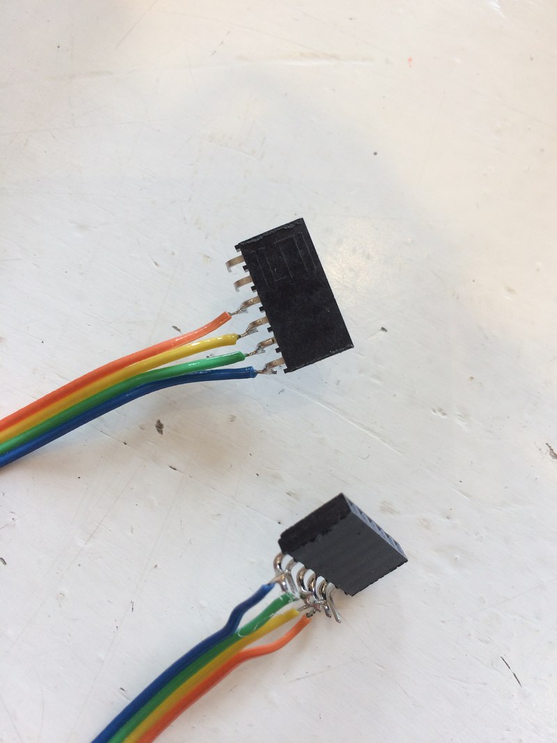
I made a ribbon cable to connect the printer and the harp. It has 6-pin female headers, though only uses four of the pins. One is wired to connect to the VCC, GND, and TX and RX of the FTDI on the PCB, the other connects those to the Ultimaker. I still never solved why the Arduino needs to be plugged in on the Ultimaker for it to work, but my workaround is to supply the Harp with VCC, and the Harp supplies the Ultimaker's Arduino with VCC, so there will only be one cable between the machines.The PCB will be supplied by a bench power supply, but there is no reason I couldn't just use a wall wart.
I cannot reliable determine if it is safe to power the Arduino in the Ultimaker through its 5V pin, so I will power it by a USB cable and the PCB will only send serial data.
The PCB connection cable is Blue: GND, Green: VCC, Yellow: Arduino RX, Orange: Arduino TX. The Ultimaker cable is red: TX, brown: RX. So the connection should go Red - Yellow, Brown - Orange
Ultimately, I knew that the 5V pin from the ultimaker could power the Harp's Arduino, so I decided to have the ultimaker power the harp. I made a ribbon cable to connect them (it has since been replaced by one using heat-shrink to isolate the solder joints):
Before I assembled the form I wanted to make sure that the PCB could communicate to the Ultimaker. I modified my Arduino programme to have each FSR send the extruder to a different XY coordinate when pressed. It works! Now I can assemble everything.
/*  The Harp
 *  Fab Academy
 *  David McCallum, 2018
 *  sintheta.org
 *
 */

char* testLocations[] = {
  "G1 X50 Y10",
  "G1 X45 Y20",
  "G1 X35 Y30",
  "G1 X20 Y40",
  "G1 X35 Y50",
  "G1 X45 Y60",
};


//#include <SoftwareSerial.h>

//#include <AltSoftSerial.h>

//const int rx = 2;
//const int tx = 3;

//AltSoftSerial ser;

const int ledPin = 9;


char okString[3];
int stringPos = 0;

const int gcodeBaseSpeed[6] = {1200, 1200, 1200, 1200, 1200, 1200};    // the base speed of a given segment of gcode
int currentLocation[2] = {50,50};


const int playThreshold = 100;    // what sensor value is needed to start playing?

int sensors[6];     // the analogRead value of each of the sensors

int whosPlaying = -1;   // which sensor is playing now, -1 is none.

int inByte = -1;      // serial read byte


void setup() {

  Serial.begin(250000); // hardware serial to printer
  //ser.begin(9600);      // software serial to computer
  //ser.println("Ready.");

  //checkConnected();

  goToCentre();

}

void loop() {

  getSensors();   // read the sensors
  //printSensors();
  listening();    // is someone playing?
  //Serial.print("Listening: ");
  //Serial.println(whosPlaying);

  delay(100);

  shine();


  if (whosPlaying != -1) {

    Serial.write("G1 F4800\n");
    Serial.write(testLocations[whosPlaying]);
    Serial.write("\n");
    Serial.println();
    whosPlaying = -1;

    delay(100);

    //start iterating through that sensor's gcode

    /*    the sensitive way
    while (sensors[whosPlaying] > 0) {
      go to next gcode


    }

    */


  }

}


void waitForOK() {

  // wait for something in serial
  while (!Serial.available()) {
    // maybe have a timeout here?
  }

  // read once something's here
  while(Serial.available()) {
    inByte = Serial.read();
    okString[stringPos] = inByte;
    stringPos++;
  }
  stringPos = 0;    // reset the string reader


}

// See if the printer is connected
void checkConnected() {

  // If there is no serial data
  while (!Serial.available()) {
    Serial.write("G4 P0\n");     // send harmless gcode
    delay(500);               // wait a bit, maybe the machine is booting
  }

  //When there's finally serial data
  if (Serial.available()) {
    while (Serial.available()) {    // empty the buffer by continuously reading from it until it's empty
      Serial.read();
    }
  }
}

// put sensor values into the array
void getSensors() {
  for (int i = 0; i < 6; i++) {
    sensors[i] = analogRead(i);
    }
}


// decide which sensor is active
void listening() {

  for (int i = 0; i < 6; i++) {

    if (sensors[i] > playThreshold) {
      whosPlaying = i;
      }

  }
}


void printSensors() {

  for (int i = 0; i < 6; i++) {
    Serial.print("Sensors: ");
    Serial.print(sensors[i]);
    Serial.print('\t');

  }
}

// move the printer's extruder
void goToCentre() {
  Serial.write("G1 X50 Y50");
  currentLocation[0] = 50;
  currentLocation[1] = 50;
}

void shine() {
  analogWrite(ledPin, map(sensors[whosPlaying], 0, 1024, 0, 255));
}

/* old shine()
// compare the values of all the sensors and use that to shine the LED
void shine() {
  int thing = -1;
  for (int i = 0; i < 6; i++) { thing = max(thing, map(sensors[i], 0, 1024, 0, 255)); }
  analogWrite(ledPin, thing);


}

*/


/*
 *  Test functions
 */


/*

void testSensorJump() {
  int sensor1data = analogRead(0);

  if (sensor1data > 400) {
    int randX = random(100);
    int randY = random(100);

    ser.print("G1 X");
    ser.print(randX);
    ser.print(" Y");
    ser.print(randY);
    ser.print("\n");

    Serial.print("G1 X");
    Serial.print(randX);
    Serial.print(" Y");
    Serial.print(randY);
    Serial.print("\n");

  }

  delay(250);


}

*/


//// listen to softwareserial, echo is out the FTDI serial
//void testEchoSerial() {
//  while (ser.available()) { Serial.write(ser.read()); }
//
//
//  /*
//    if (ser.available()) {
//    int inByte = ser.read();
//    Serial.write(inByte);
//
//  }
//  */
//
//}


/*


void serialBridge() {
  while (Serial.available()) { ser.write(Serial.read()); }
  while (ser.available()) { Serial.write(ser.read()); }
}

*/

void testSerialBlink() {
  while (Serial.available()) {
    Serial.read();
    digitalWrite(13, HIGH);
    delay(10);
    digitalWrite(13, LOW);
    delay(10);

  }


}
Also a note: turn on the Arduino before turning on the motors.
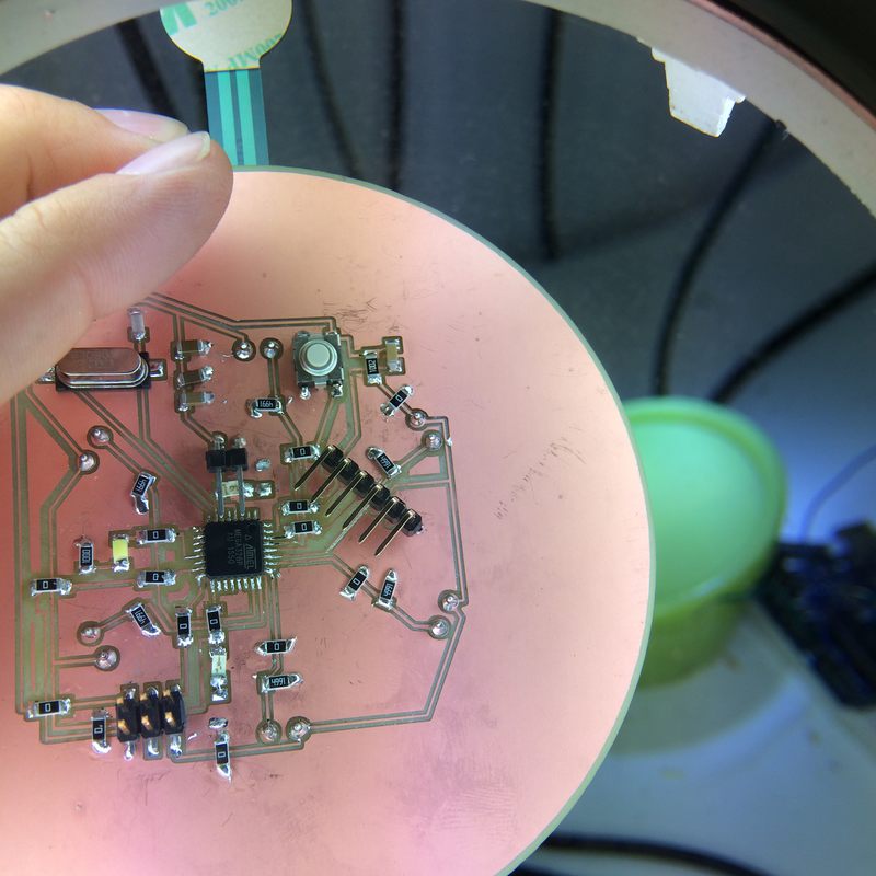
I also placed all the through-hole components on the underside of the board now. It made more sense to have the connections coming from the underside of the board.
After my code that successfully has each sensor move the extruder to a specific XY location, I am trying to figure out how to lower my expectations while still designing behaviour that is somewhat interesting. My goal behaviour for the presentation will be: stroke a rod, when the stroke is finished, the maximum pressure will determine the speed of the expression, and the expression will then be executed. So, no aftertouch control. I think this could still be somewhat rewarding.
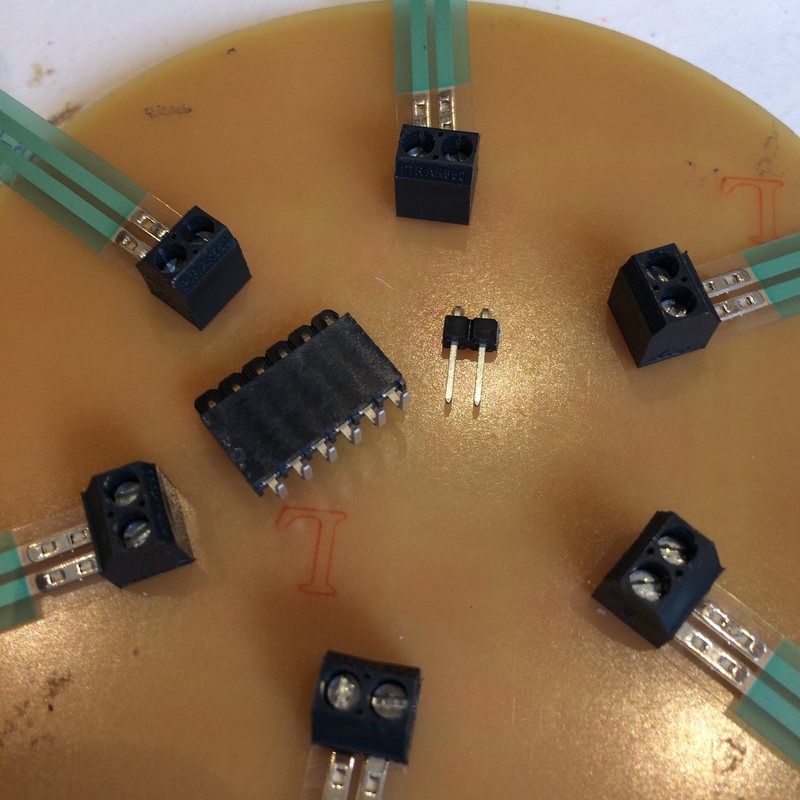
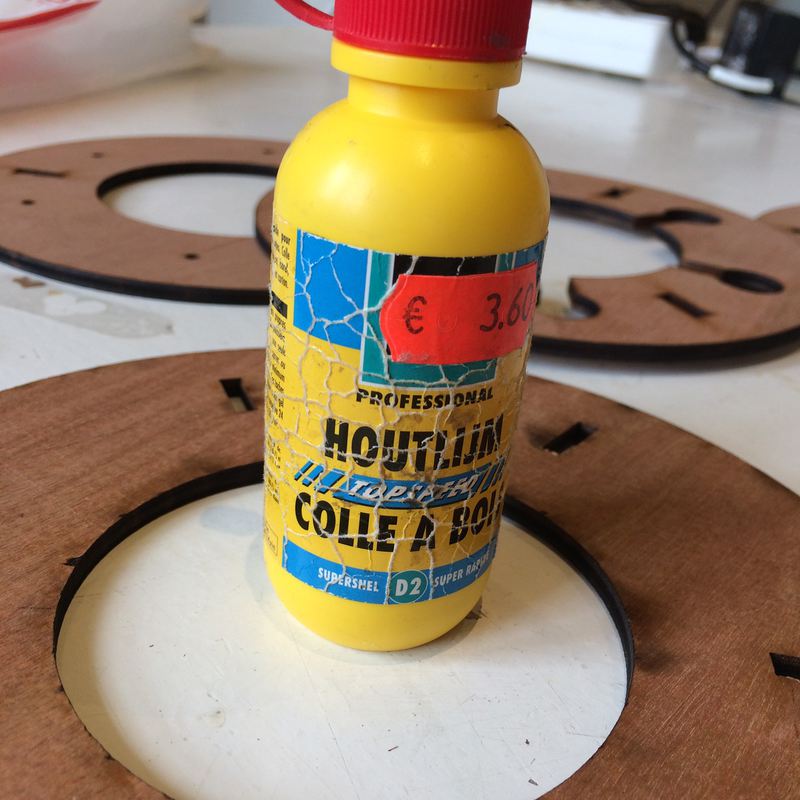
I began to assemble the frame. I marked one the bottom layer where the FSR heads will be placed, but I am still having alignment problems. It appears that the screw terminals are not evenly placed. This is what I get from doing some PCB placement by eye. I am using wood glue to attach pieces.
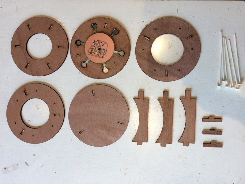
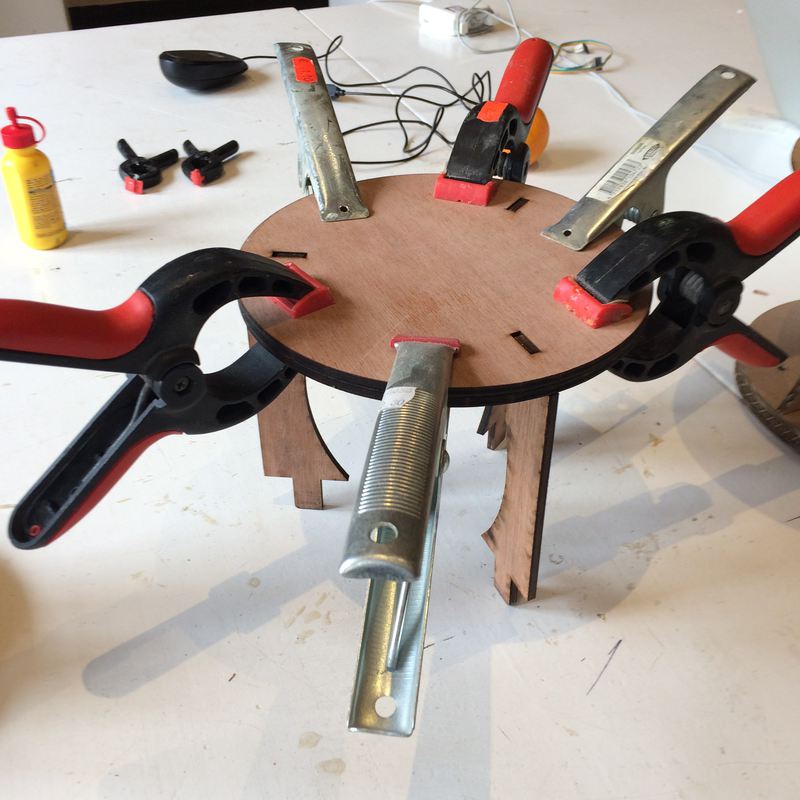
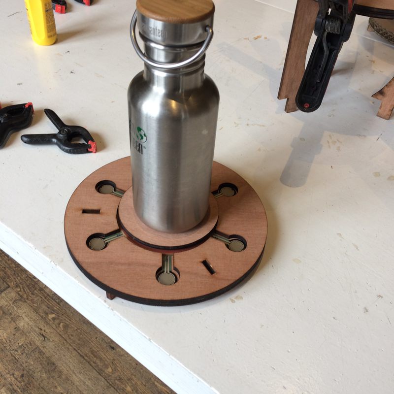
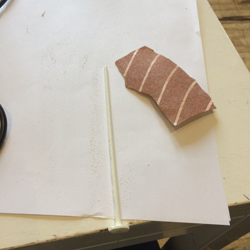
The rods also didn't quite fit smoothly through the holes. I used a knife and sandpaper to remove the supports, and used a little more sandpaper to make sure they were not catching in the frame.
2018-06-14
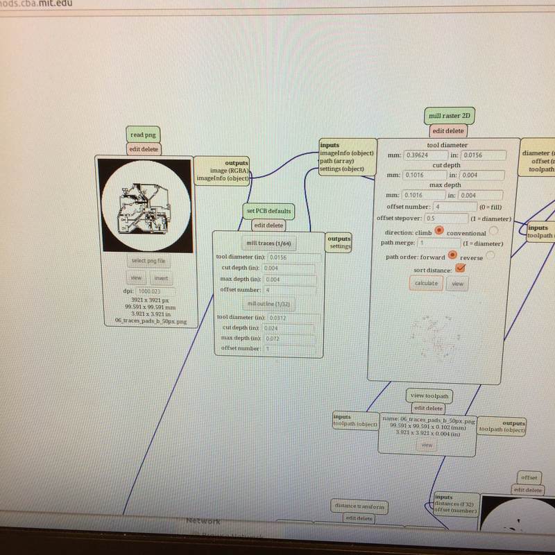
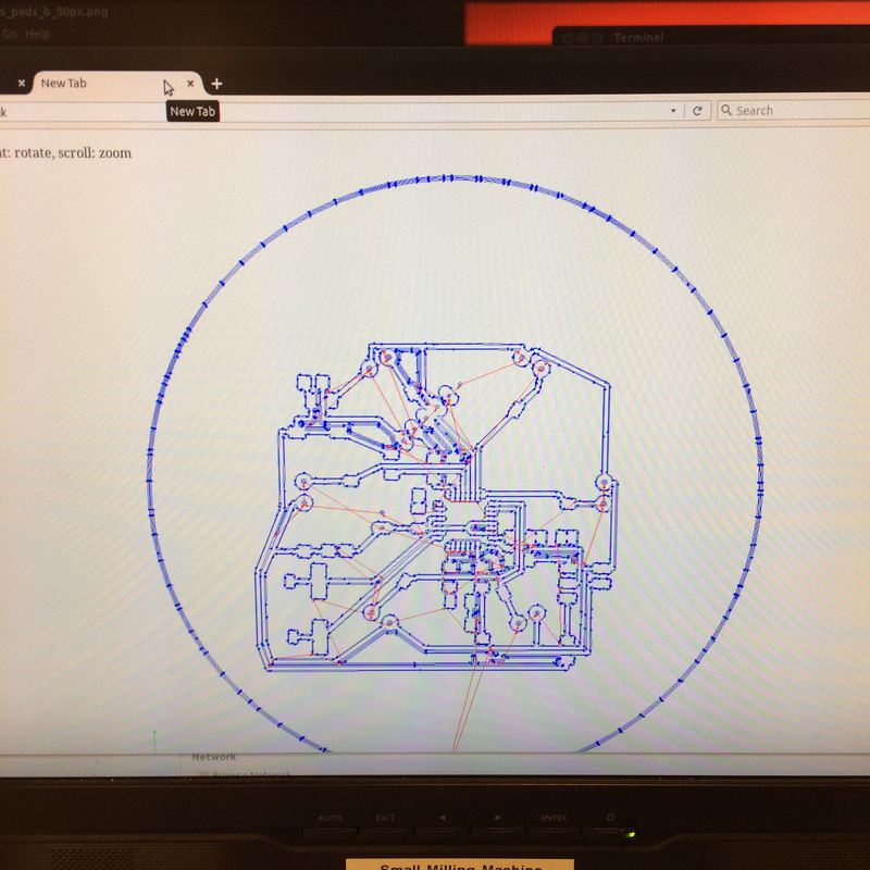
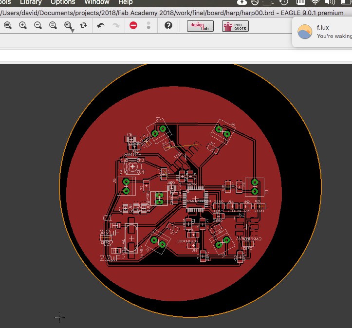
I had a weird circle sitting across my PCB, but I wanted the ground-plane circle to cover the whole PCB. this tutorial showed exactly how to do that.
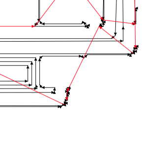
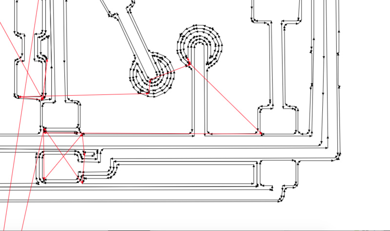
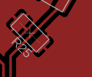
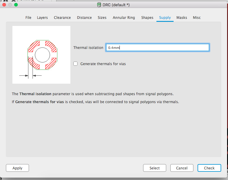
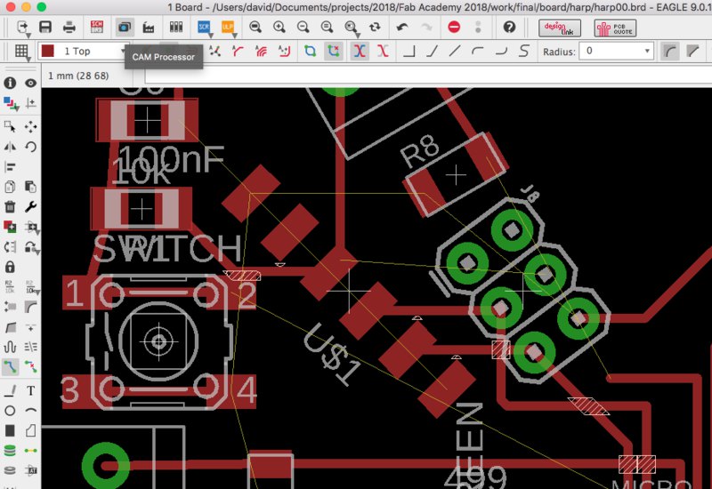
I then uploaded the images to mods and examined the traces. Some areas were not being milled. It looked like some of the corners between pads and the ground plane were being cut short, not leaving enough room for the endmill. Increasing the "isolation" property of the ground-plane polygon did not affect these corners. I unselected "thermals", and these traces were no longer created, eliminating this problem. I did another DRC to check that nothing changed, and everything was still fine. Here are images showing the ground plane specs, with a checkbox for thermals and a field for isolation. Then a screenshot of mods not tracing the milling path, and then it tracing the path properly. The last image shows that the isolation of the traces is larger than the isolation of the thermals.
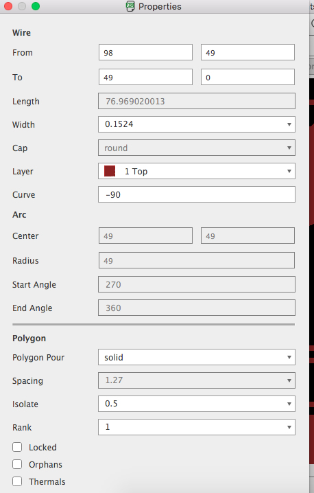

Emma said that not using thermals creates problem when soldering, because the heat dissapates quickly to the surrounding area. I didn't know what else to do, so I began milling the board without the thermals. Then I googled "fab academy milling thermals" and… I found a solution. This page says that the way to change the thermal isolation is in the DRC under "supply". That's right. The way to change an object's parameters is through a diagnostic tool. Add this to the list of things that are counterintuitive in Eagle and give me cause to find an alternative, which I'll do as soon as I'm done this project. Oh, and of course you have to use the "ratsnest" tool to see any changes you've just implement.
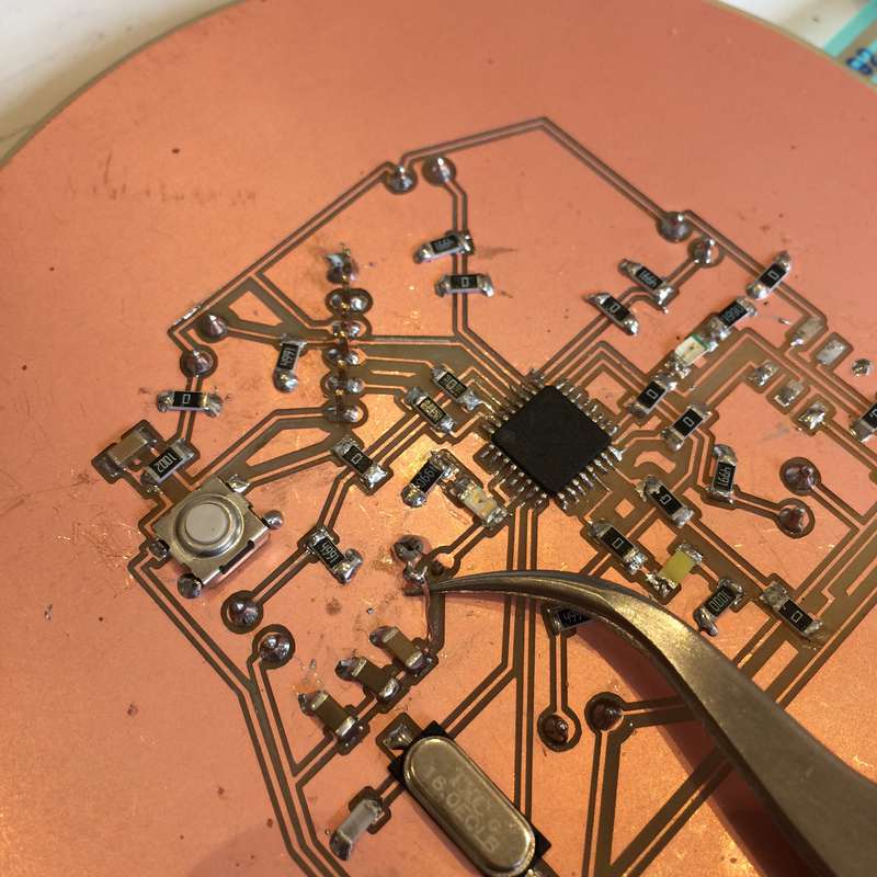
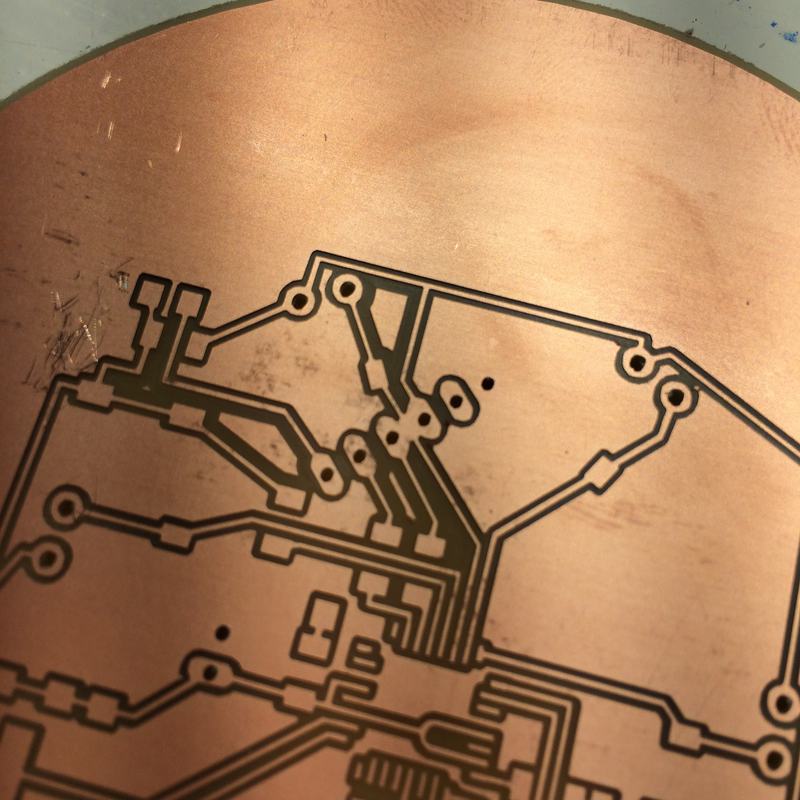
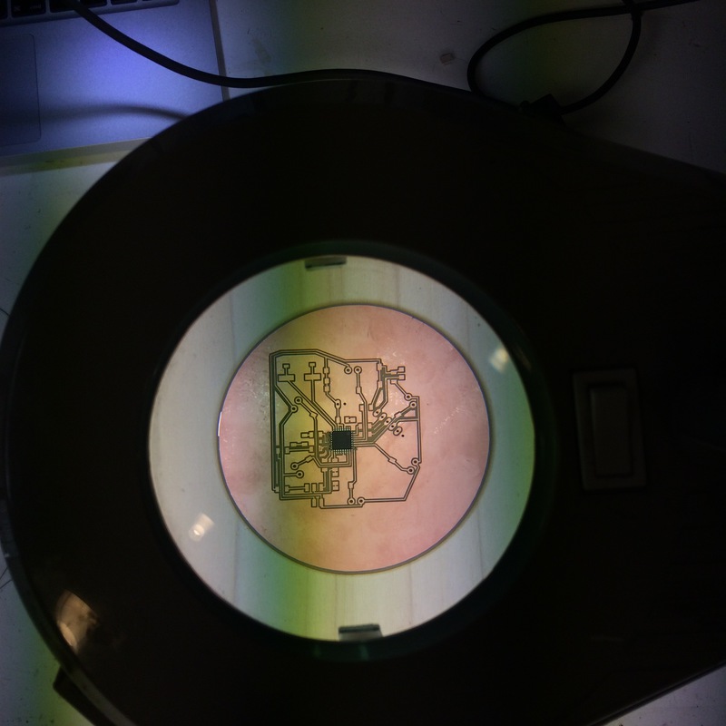
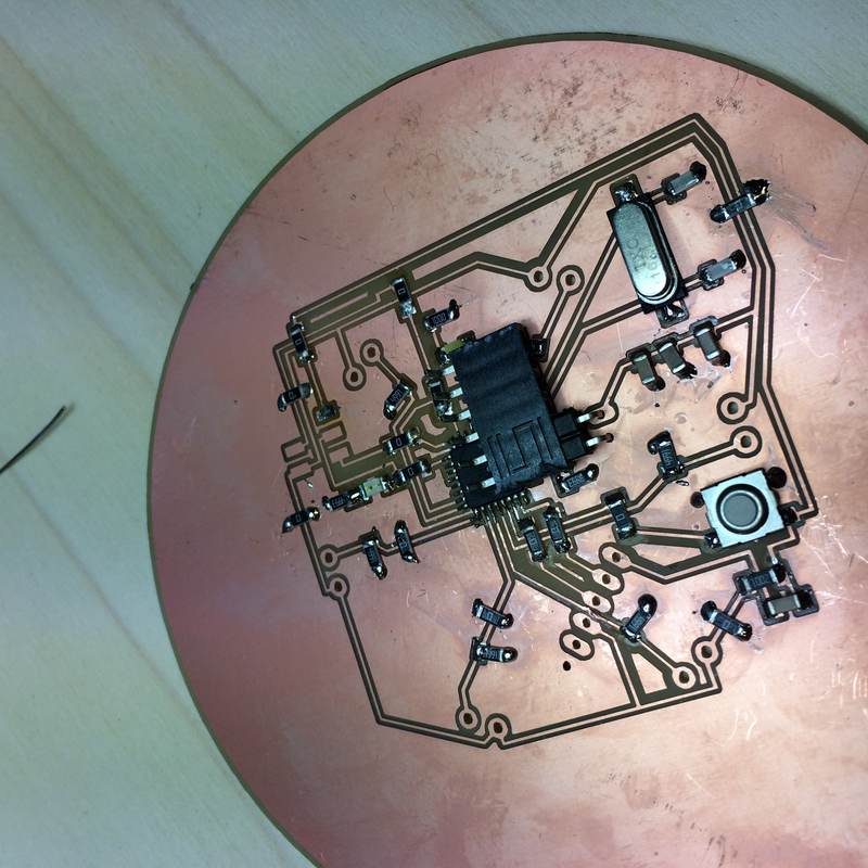
And then I held my breath and milled! And soldered!
I used the ULP in Eagle called bom.ulp to generate a bill of materials. The resistors without values are the resistors for the FSRs, whose values I will have to test again with my new FSR parts.
Part      Value            Device               Package       Description                                                                   MF    MPN            OC_FARNELL OC_NEWARK SUPPLIER TOLERANCE VALUE VOLTAGERATING
C1        2.2µF            0612ZC225MAT2A       CAPC3216X178N Capacitor 1206                                                                      0612ZC225MAT2A -          12N3209   AVX      ±20%      2.2µF 10V
C2        2.2µF            0612ZC225MAT2A       CAPC3216X178N Capacitor 1206                                                                      0612ZC225MAT2A -          12N3209   AVX      ±20%      2.2µF 10V
C3        10uF             CAP1206              1206          Capacitor
C4        1uF              CAP1206              1206          Capacitor
C5        100nF            CAP1206              1206          Capacitor
C6        100nF            CAP1206              1206          Capacitor
CRYSTAL   16Mhz            CSM-7X-DU            CSM-7X-DU     SMD CRYSTAL                                                                                        unknown    unknown
J1        TERM-1X02-FABLAB TERM-1X02-FABLAB     ED555DS-2DS   3.5mm terminal block, 2 positions ED555-2DS as found in the fablab inventory.
J2        TERM-1X02-FABLAB TERM-1X02-FABLAB     ED555DS-2DS   3.5mm terminal block, 2 positions ED555-2DS as found in the fablab inventory.
J3        TERM-1X02-FABLAB TERM-1X02-FABLAB     ED555DS-2DS   3.5mm terminal block, 2 positions ED555-2DS as found in the fablab inventory.
J4        TERM-1X02-FABLAB TERM-1X02-FABLAB     ED555DS-2DS   3.5mm terminal block, 2 positions ED555-2DS as found in the fablab inventory.
J5        TERM-1X02-FABLAB TERM-1X02-FABLAB     ED555DS-2DS   3.5mm terminal block, 2 positions ED555-2DS as found in the fablab inventory.
J6        TERM-1X02-FABLAB TERM-1X02-FABLAB     ED555DS-2DS   3.5mm terminal block, 2 positions ED555-2DS as found in the fablab inventory.
JP1                        PINHD-1X06_2.54      1X06          PIN HEADER
LED_GREEN LEDFAB1206       LEDFAB1206           LED1206FAB    LED
MICRO     ATMEGA328P-AU    ATMEGA48/88/168-AU   TQFP32-08
POWER     22-23-2021       22-23-2021           22-23-2021    .100" (2.54mm) Center Header - 2 Pin                                          MOLEX 22-23-2021     1462926    25C3832
R1        ZERO             RES-US1206FAB        R1206FAB      Resistor (US Symbol)
R2        499              RESISTOR1206         1206          Resistor
R3        ZERO             RES-US1206FAB        R1206FAB      Resistor (US Symbol)
R4                         RES-US1206FAB        R1206FAB      Resistor (US Symbol)
R5                         RES-US1206FAB        R1206FAB      Resistor (US Symbol)
R6                         RES-US1206FAB        R1206FAB      Resistor (US Symbol)
R7                         RES-US1206FAB        R1206FAB      Resistor (US Symbol)
R8                         RES-US1206FAB        R1206FAB      Resistor (US Symbol)
R9                         RES-US1206FAB        R1206FAB      Resistor (US Symbol)
R10                        RES-US1206FAB        R1206FAB      Resistor (US Symbol)
R11       0 OHM            RES-US1206FAB        R1206FAB      Resistor (US Symbol)
R12       10K              RES-US1206FAB        R1206FAB      Resistor (US Symbol)
R13       ZERO             RES-US1206FAB        R1206FAB      Resistor (US Symbol)
R14       ZERO             RES-US1206FAB        R1206FAB      Resistor (US Symbol)
R15       499              RES-US1206FAB        R1206FAB      Resistor (US Symbol)
R16       ZERO             RES-US1206FAB        R1206FAB      Resistor (US Symbol)
R17       ZERO             RES-US1206FAB        R1206FAB      Resistor (US Symbol)
R18       ZERO             RES-US1206FAB        R1206FAB      Resistor (US Symbol)
R19       ZERO             RES-US1206FAB        R1206FAB      Resistor (US Symbol)
R20       ZERO             RES-US1206FAB        R1206FAB      Resistor (US Symbol)
R21       ZERO             RES-US1206FAB        R1206FAB      Resistor (US Symbol)
R22       ZERO             RES-US1206FAB        R1206FAB      Resistor (US Symbol)
R23       ZERO             RES-US1206FAB        R1206FAB      Resistor (US Symbol)
R24       ZERO             RES-US1206FAB        R1206FAB      Resistor (US Symbol)
R25       ZERO             RES-US1206FAB        R1206FAB      Resistor (US Symbol)
SWITCH                     6MM_SWITCH6MM_SWITCH 6MM_SWITCH    OMRON SWITCH
U$2       AVRISPSMD        AVRISPSMD            2X03SMD
U$3       LEDFAB1206       LEDFAB1206           LED1206FAB    LED
U$4       YELLOW           LEDFAB1206           LED1206FAB    LED
I found the datasheet for the white LED on Octopart. I used an online calculator to find the current-limiting resistor value. It calculated 75Ohm, so I used 100Ohm.
Tested the behaviour of the new FSRs, and with a 15K resistor I get a range between 0 and 1000, which is great. Although… we don't have 15K SMD resistors. I could bend the legs of THT resistors and solder them on… or… instead I test the values of SMD resistors we have. 50K and 5K. 50K is a little too sensitive, with most of the sensor values resting above 500. The 5K works fine. Similar to the 15K. That's what I go with.
Tested the power of my circuit. Problem. Turning on the power supply drives the current to 0. That means… a short? Something is wrong… or… Maybe not? Maybe that's fine. It's just not drawing much yet.
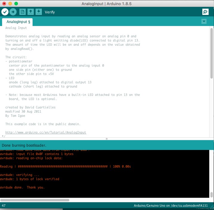
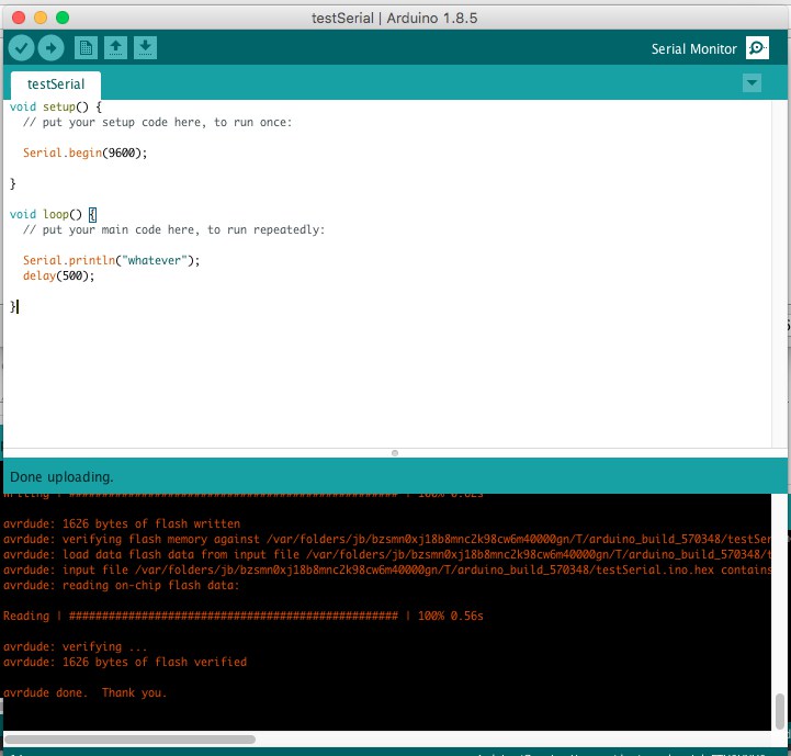
I tried simply holding the ISP header to the board and burning the bootloader, but it kept shorting and the USB port on my computer shut off. I soldered the 6-pin header and… successfully burned the bootloader first try! And a simple sketch to return serial data also worked.
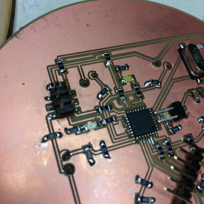
Two LEDs on the board are not working. Neither are important, but it's weird that they don't work. The pin13 LED that's ok most Arduinos, and an LED for the power to the board. I checked the orientation. I checked the datasheet and saw that the resistors were OK. So… what's the problem?
Emma, wonderful Emma, discovered that I had put 500K resistors as current-limiting resistors for the LEDs instead of 500 Ohms. Did I grab the wrong ones? Were they mis-filed in the boxes? We'll never know. And then… I kept getting warnings that the USB port was being disabled because it was drawing too much. A short. I removed the current-limiting resistors I was playing with, in case there was sloppy soldering. Nothing. Until… I noticed a little blob of solder that happened to fall on two traces. I used some solder wick and… omg it works. No short. AND I replaced the current-limiting resistors and they work. Yay!
Once the board was all put together. I wrote a simple Arduino sketch to test that everything worked. The highest sensor value controlled the brightness of the LED. The code iterates through the sensor value, comparing each to the previous and choosing the highest using max(), and then mapping the result between 0 and 255 using map(). In retrospect, I should have just mapped at the end of the max() calculation.
int sensorPin = A5; // select the input pin for the potentiometer
int ledPin = 13; // select the pin for the LED
int sensorValue = 0; // variable to store the value coming from the sensor
int ledValue = 0;
void setup() {
// declare the ledPin as an OUTPUT:
pinMode(ledPin, OUTPUT);
Serial.begin(9600);
}
void loop() {
// read the value from the sensor:
sensorValue = analogRead(sensorPin);
int aa0 = analogRead(A0);
int aa1 = analogRead(A1);
int aa2 = analogRead(A2);
int aa3 = analogRead(A3);
int aa4 = analogRead(A4);
int aa5 = analogRead(A5);
ledValue = max(map(aa0, 0 , 1024, 0, 255), map(aa1, 0 , 1024, 0, 255));
ledValue = max((ledValue), map(aa2, 0 , 1024, 0, 255));
ledValue = max((ledValue), map(aa3, 0 , 1024, 0, 255));
ledValue = max((ledValue), map(aa4, 0 , 1024, 0, 255));
ledValue = max((ledValue), map(aa5, 0 , 1024, 0, 255));
analogWrite(9, ledValue);
Serial.print(aa0);
Serial.print('\t');
Serial.print(aa1);
Serial.print('\t');
Serial.print(aa2);
Serial.print('\t');
Serial.print(aa3);
Serial.print('\t');
Serial.print(aa4);
Serial.print('\t');
Serial.print(aa5);
Serial.println('\t');
/*
// turn the ledPin on
digitalWrite(ledPin, HIGH);
// stop the program for <sensorValue> milliseconds:
delay(sensorValue);
// turn the ledPin off:
digitalWrite(ledPin, LOW);
// stop the program for for <sensorValue> milliseconds:
delay(sensorValue);
*/
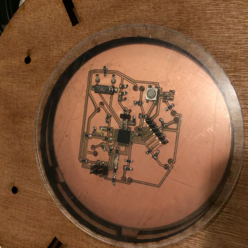
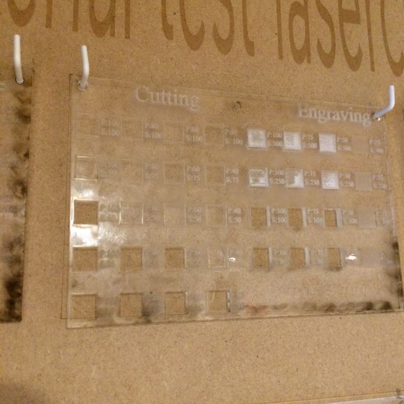
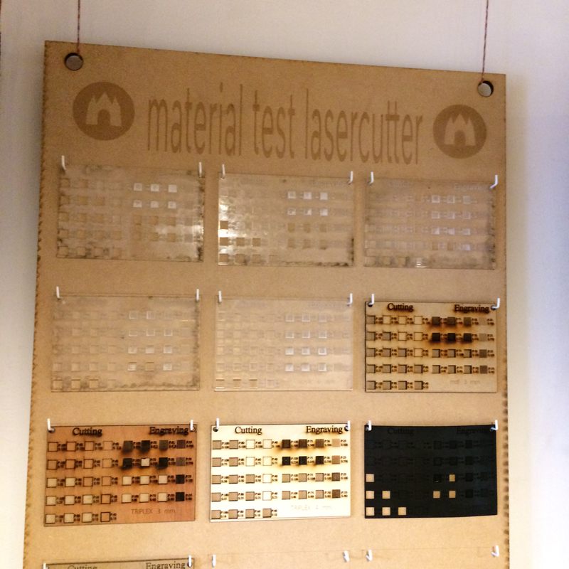
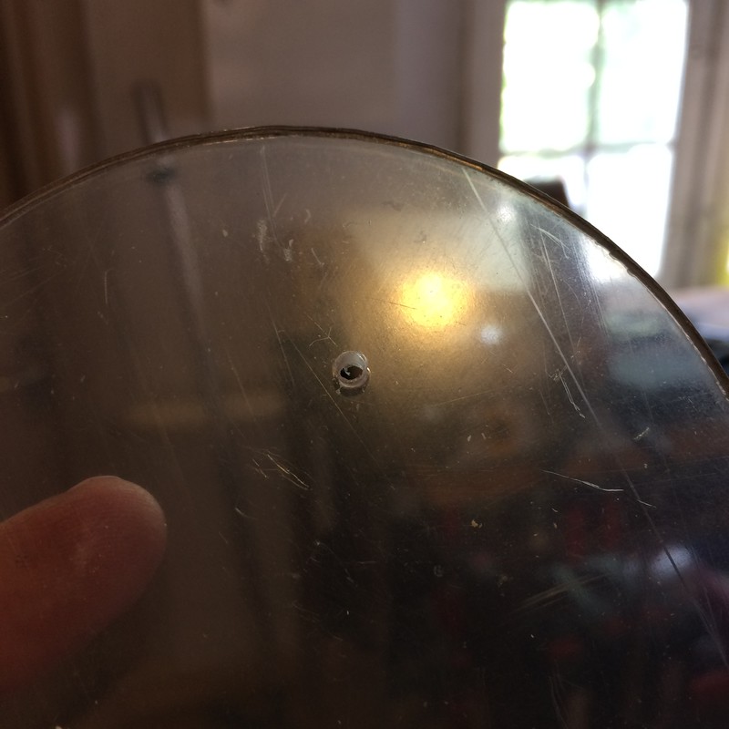
}Hanna suggested that Neil would want the electronics encapsulated, even if I wanted them exposed. And she came up with the brilliant idea to cut a piece of plexi to act as a window covering the circuit. So I found the plexi kerf for our laser cutter from our group assignment, used the settings based on the cut examples on the wall by the laser cutter, and cut a circle to fit. Magique.
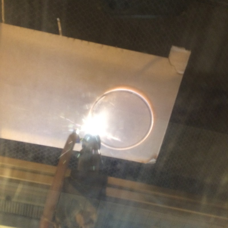
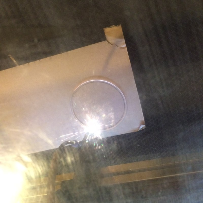
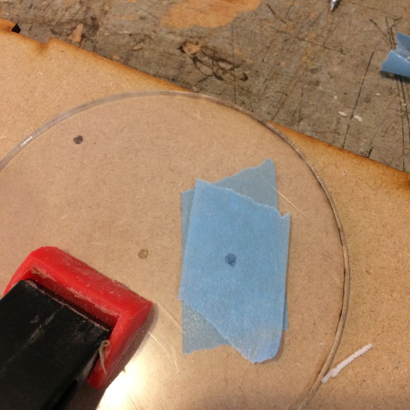
And then Emma was like "you should put a hole in the window to get at the reset switch" and I thought "I never thought of that." I should have put the reset switch on the bottom. And she said "just cut a new window", and I tried and I said "the laser cutter is broken" and Emma looked and said "yes, it's broken, you have to drill it, but make sure it doesn't crack." So I googled a million sites that said put tape on it and go slowly. So I did. And it worked.
2018-06-10
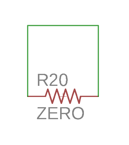
Finished routing in Eagle. Used 0Ohm resistors. Used the trick of making a ground plane following this tutorial. Found that some ground areas were still isolated, so I created some 0-Ohm resistors in the schematic and connected them to themselves, and called the net "GND". I could place these anywhere in the schematic to bride ground planes. DRC gives an error that there is an airwire between both terminals, but I approve the error and keep on going! Here is the first attempt at the ground plane, notice the air wires accross the zero-ohm resistors, and the part of the schematic that shows how I connected the zero-ohm resistors:
2018-06-09
I was having some trouble with some components. And I realised that I didn't need both a connector for the TX RX and an FTDI connector, both of which I added to make things easier. I'm just going to have the FTDI connector and use female headers to the connection to the Ultimaker. This way, I can also supply ground and VCC to the ultimaker's Arduino if I choose to. Here's the garbage I was dealing with trying to squeeze things together, note the 6-pin headers AND the FTDI:
2018-06-08
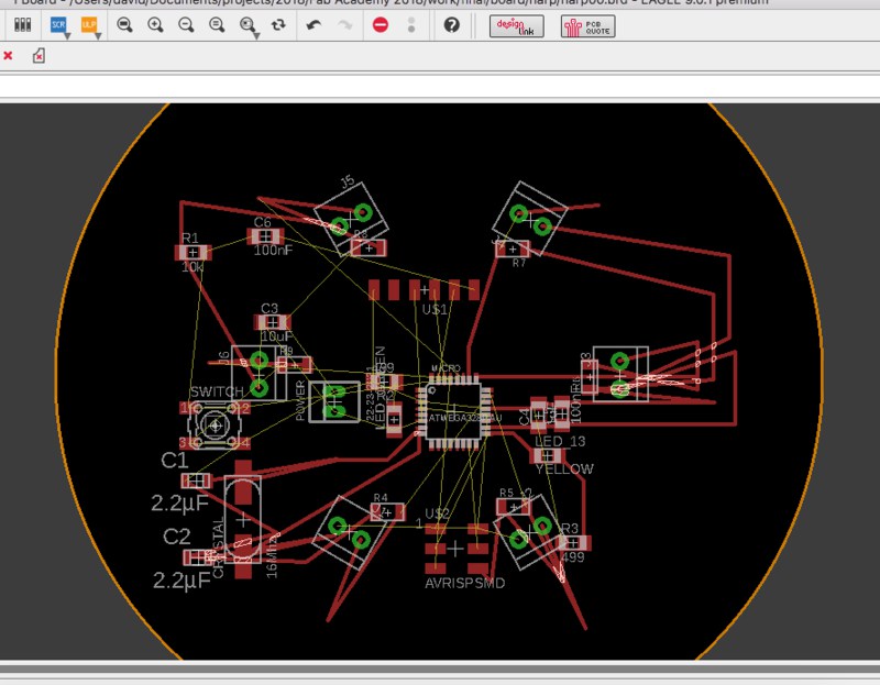
Board
PCB design. I consulted a pinout of the Atmega328P for the arduino, and placed the single LED on Arduino pin 9, chip pin PB1. . I may still supply the Ultimaker with 5V, so I added a 4-pin connector for the TX and RX to leave that possibility open. . Be aware of orientation! Here's the LED, and the connector:
Eagle DRC. I had to set minimum width to .3mm to not receive errors. I hope this mills fine. From our group assignment characterising the machine, it looks like it should be fine. Before, I set everything to .4mm for safety sake.
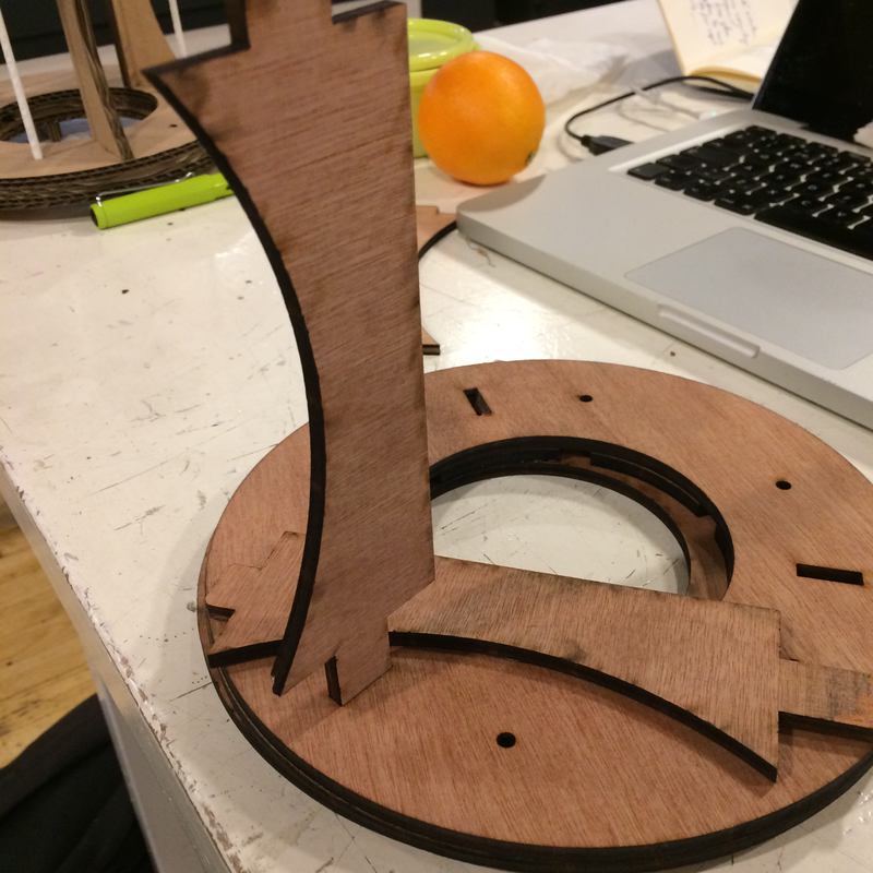
Frame
Emma helped me get some 6mm plywood from Schmidt Houthandel. Before I do the cutting in wood, I will make one final cardboard model. Because we have 3mm cardboard, I have to cut doubles of everything to assemble it as though it were 6mm.
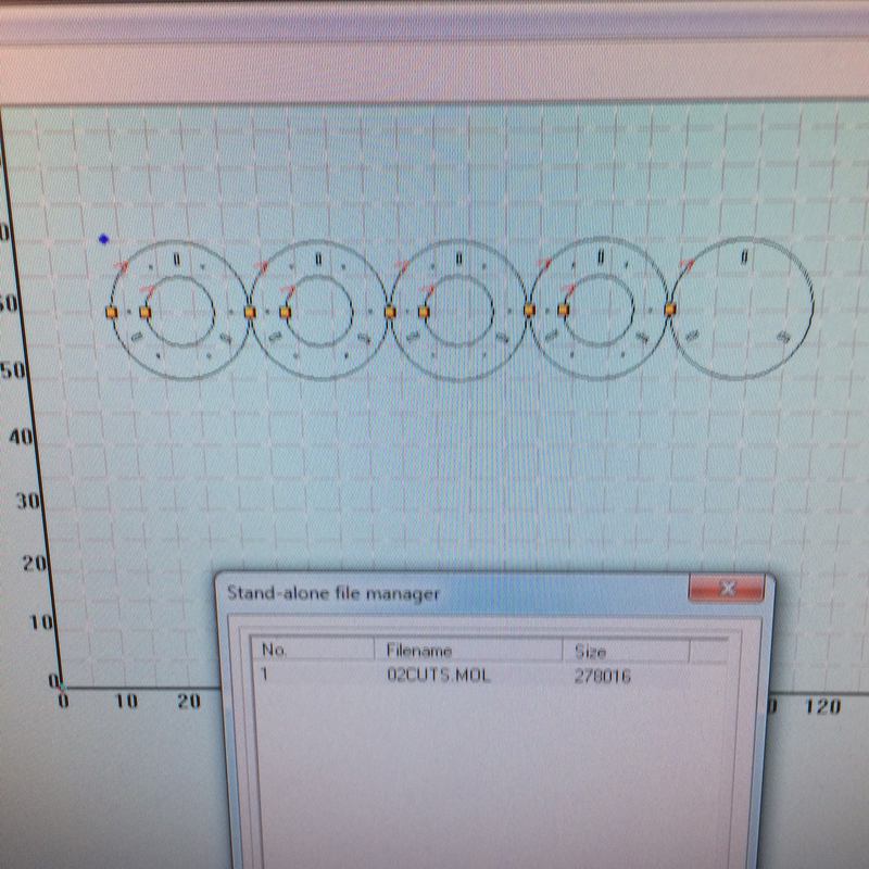
OMG. I found a way around using Illustrator as a go-between for DXF files from Fusion360 to LaserCut5.3. I used the python library ezdxf. Opening and saving the DXF files creates files that LaserCut5.3 can read. Then I wrote a simple script to process all files in the directory:
#!/opt/local/bin/python3

import os, ezdxf

for file in os.listdir('.'):
    if file.endswith(".dxf"):
        dd = ezdxf.readfile(file)
        dd.saveas('reFXD_' + file)
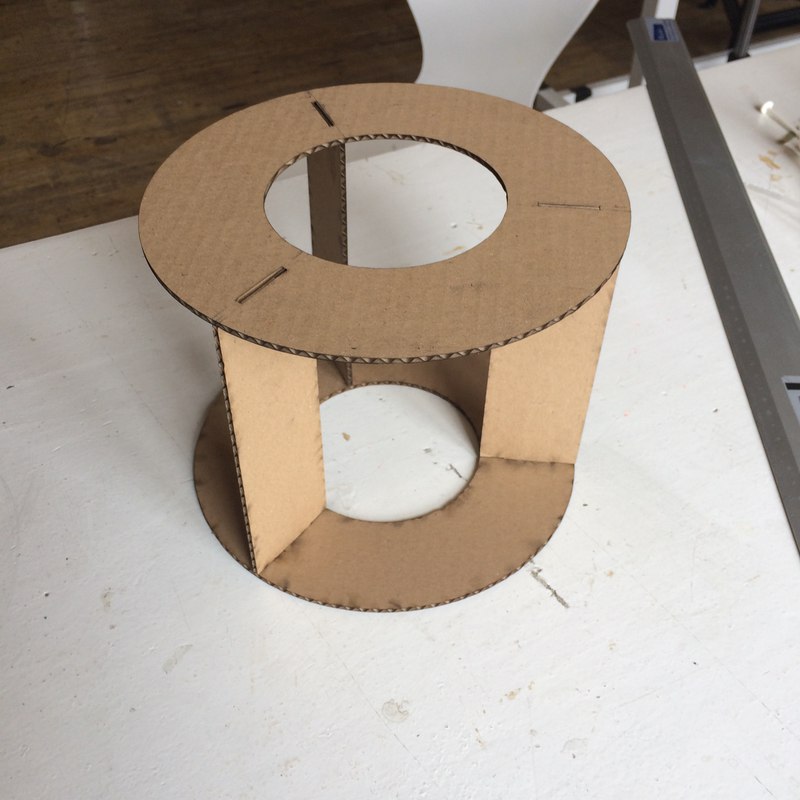
Cardboard model problems. The top is too high, and the rods come loose. The three feet are not stable enough. Solution, lengthen the legs to provide extra stability. Here's the cardboard model:
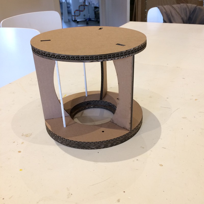
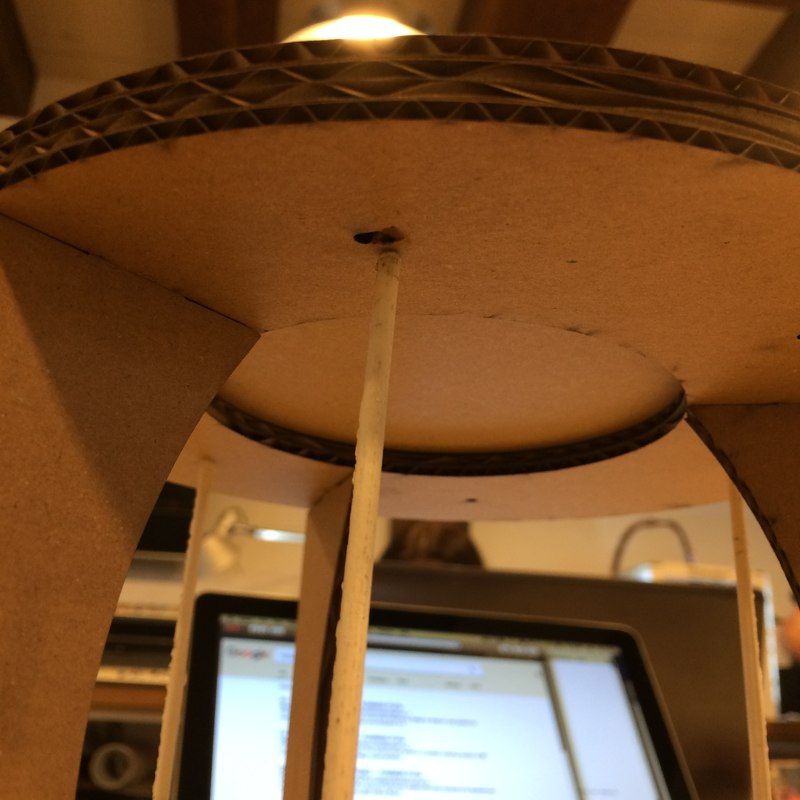
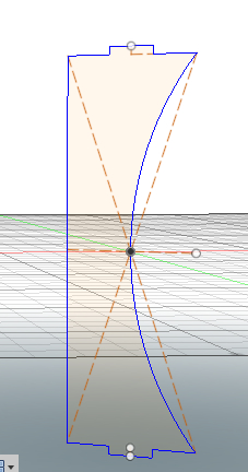
You may see that the rods are too short. Something happened in Fusion, so I opted to resize the model rather than resize and reprint the rods. Here is the model resized:
Note to self: move the screw terminals slightly closer to the FSRs in Fusion. They are just a little too far out.
Plywood
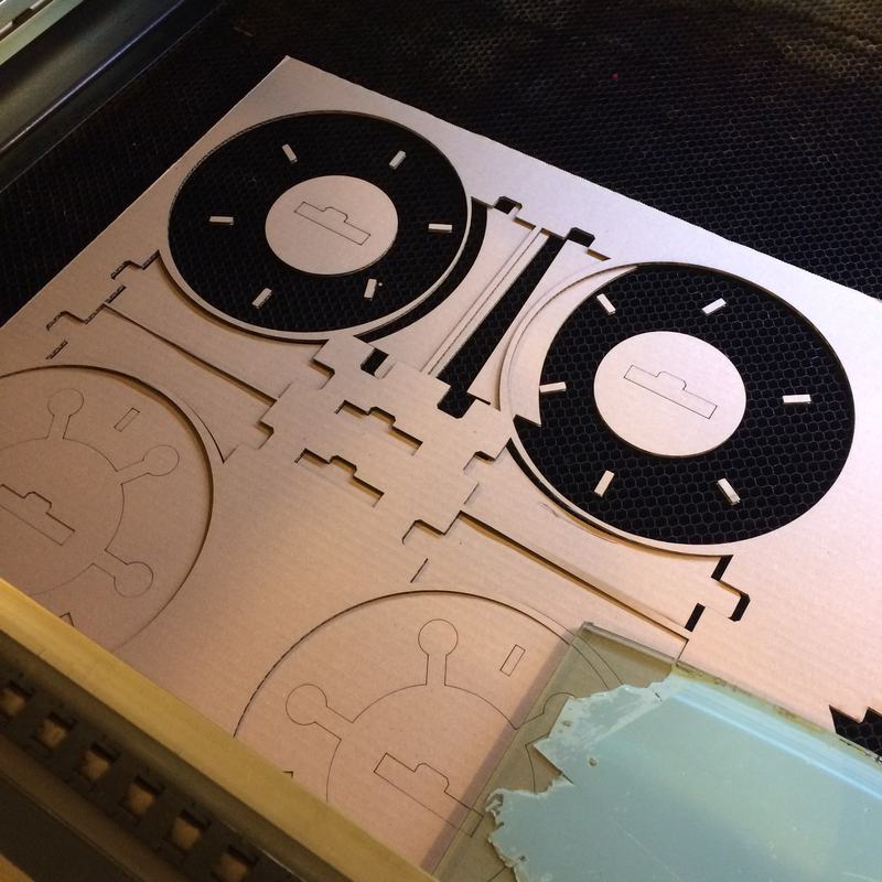
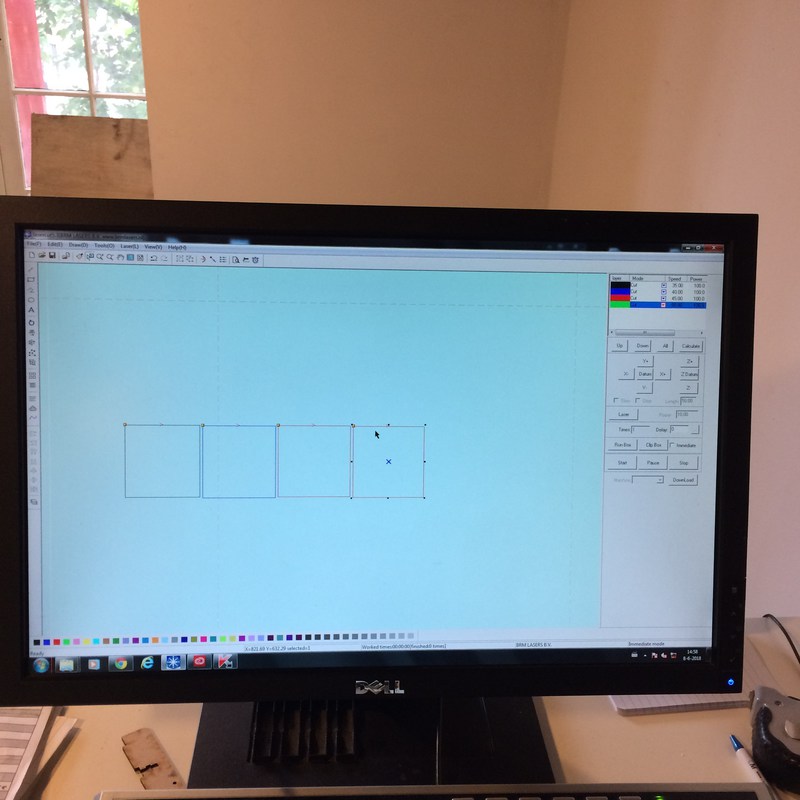
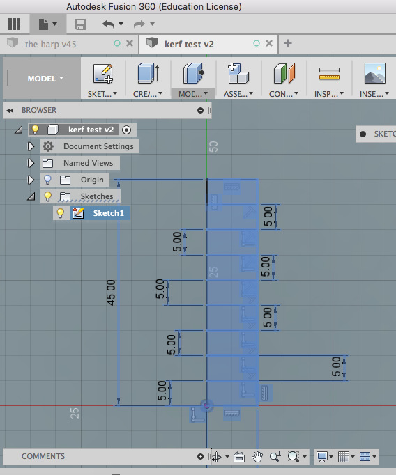
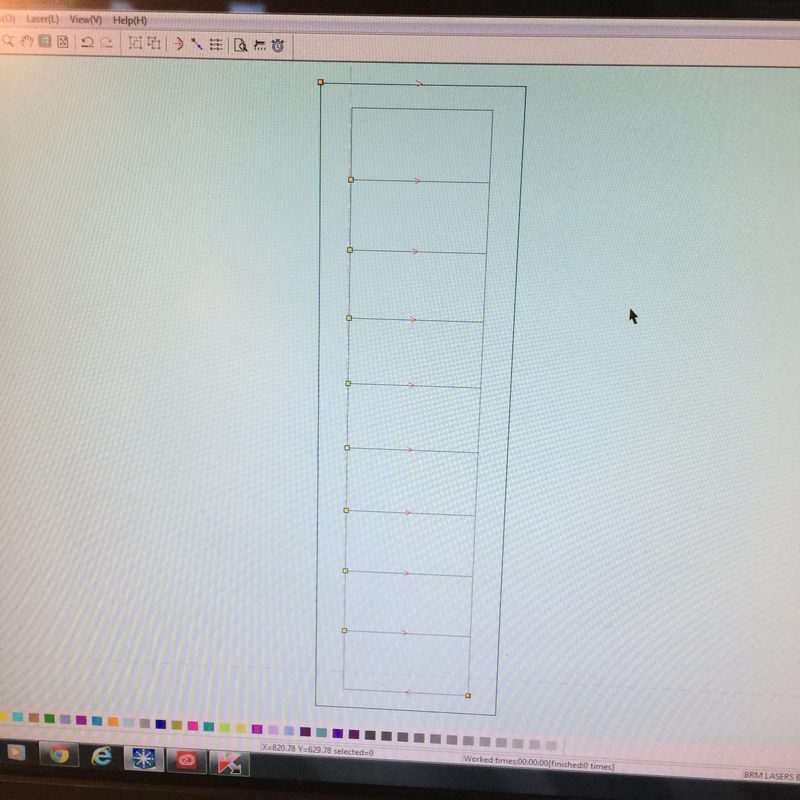
I measured the plywood. It's 5 mm, even though the shop said 6mm. Because my design was parametric I can change the material width and this shouldn't be a problem. I did some tests to see the cutting parameters for the 5mm plywood, it turned out to be the same as for the 6mm. Lowering the power or speed didn't make an appreciable difference:
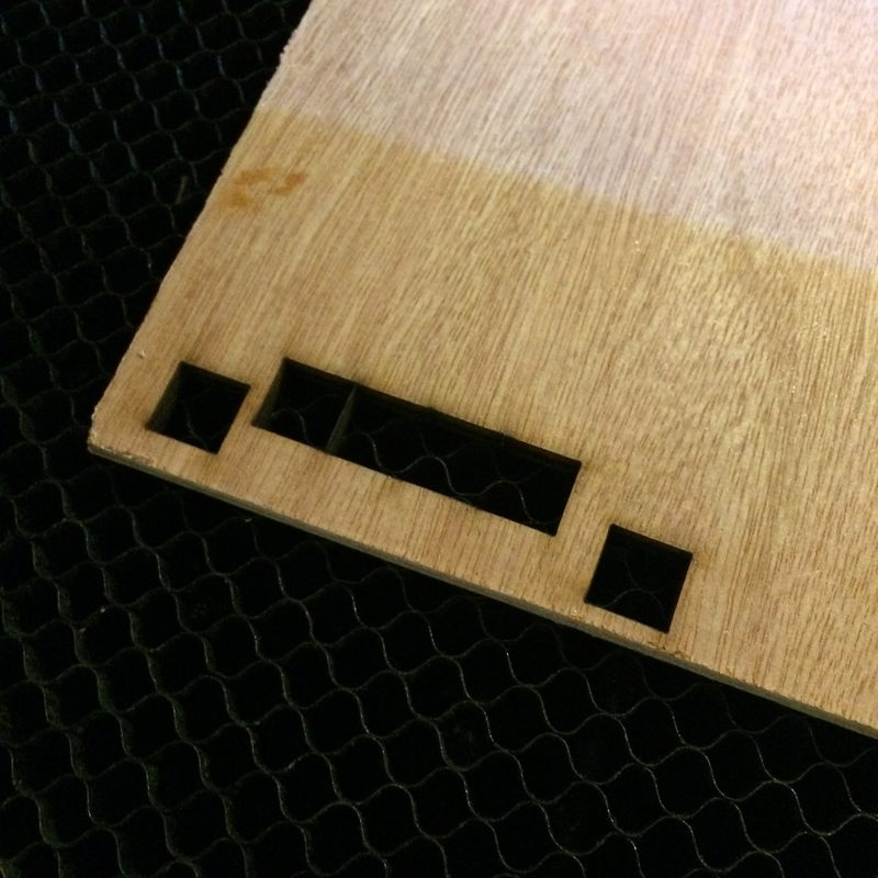
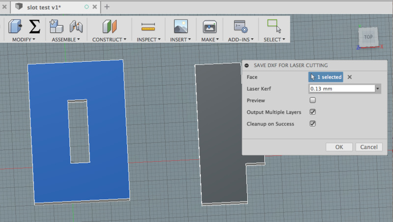
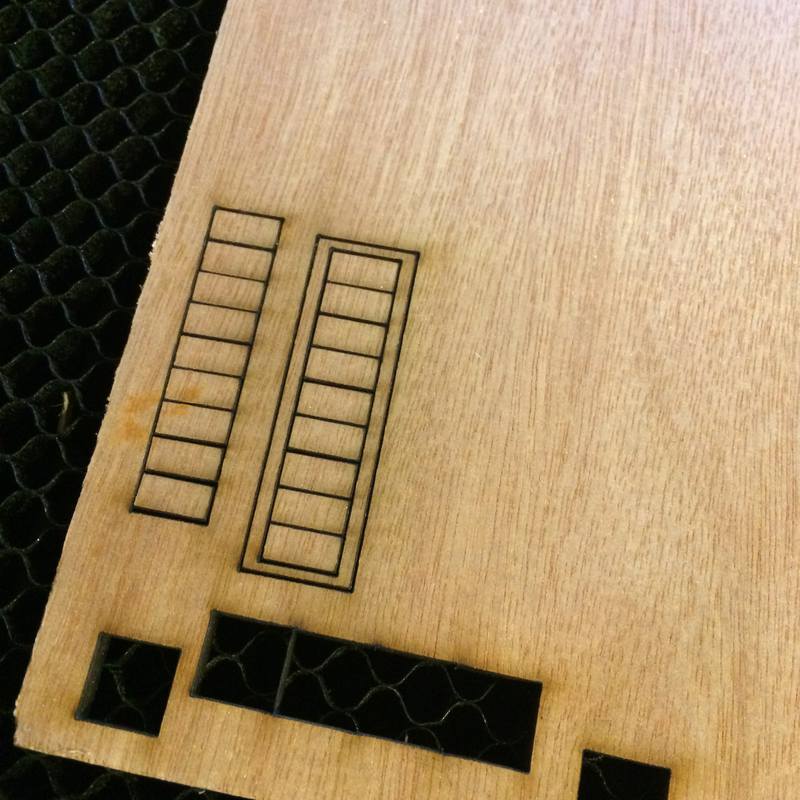
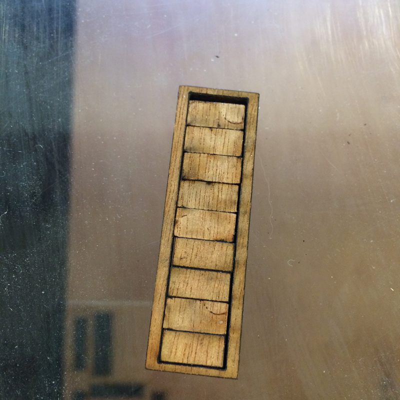
Slot test. .13mm kerf was a little too wiggly. Add some kerf. After many tests, .19mm was tight enough that it needed a little force to go in. Kerfect.
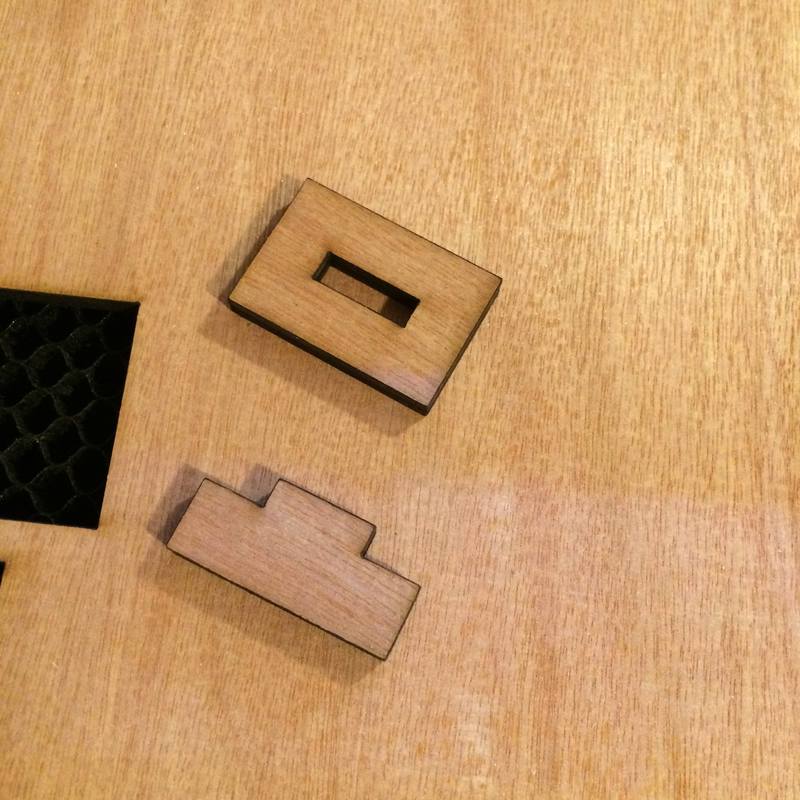
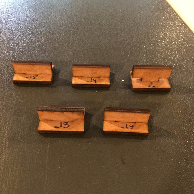
And then I cut some test pieces. And .19mm was great for a single layer, but my tabs are going through 3 layers of material, and then it becomes way too much friction. Redoing it with .18mm kerf. Actually, trying again with a 3-layer test. This piece did not want to go in easily:
The results of the 3-layer were confusing. Kerfs that were previously easy were now hard. I consulted with Emma and Cecilia who gave several reasons for why things might have changed. Laser needed cleaning? Unlikely. Laser defocussed? I checked the focus each time I cut, because the wood was warped. In the end I did several 3-layer tests and settled on .15mm. Then recut a few pieces just to test.
2018-06-07
Tried cutting two 3mm pieces of plywood to see if it would work. The log book by the laser said that speed 26 power 100 worked. I found I had to go lower in speed. Speed 23 seemed to be a lower limit.
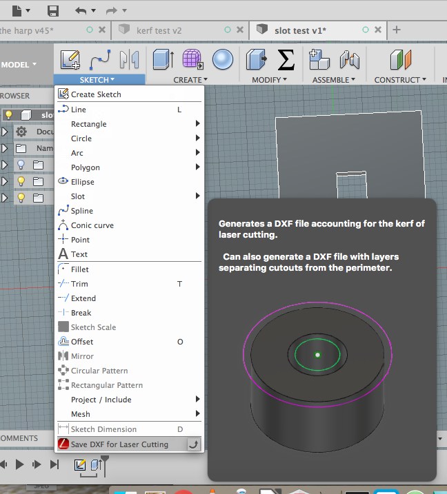
I used a Fusion add-on called DXF4Laser, which will take body outlines and generate DXF files accomodating for kerf. See?
Ordered this FSR from a local vendor, which has the same dimensions as the one I was testing with, but slightly different characteristics. Will have to test the resistor to make sure that it works OK.
kerf * 10 measured as 1.3mm for 4mm plywood, so kerf is .13 mm. Did slot tests, .13mm kerf seemed too tight. .1mm was OK. Snug.
2018-06-02
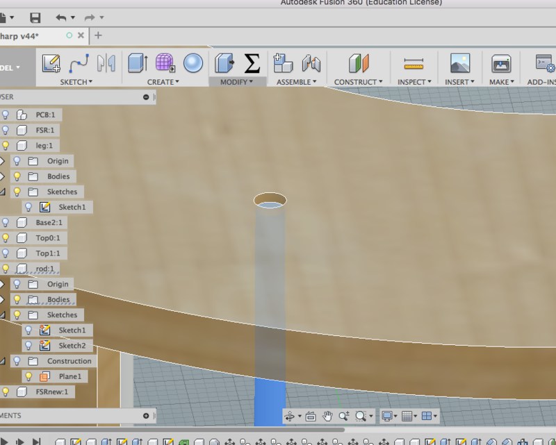
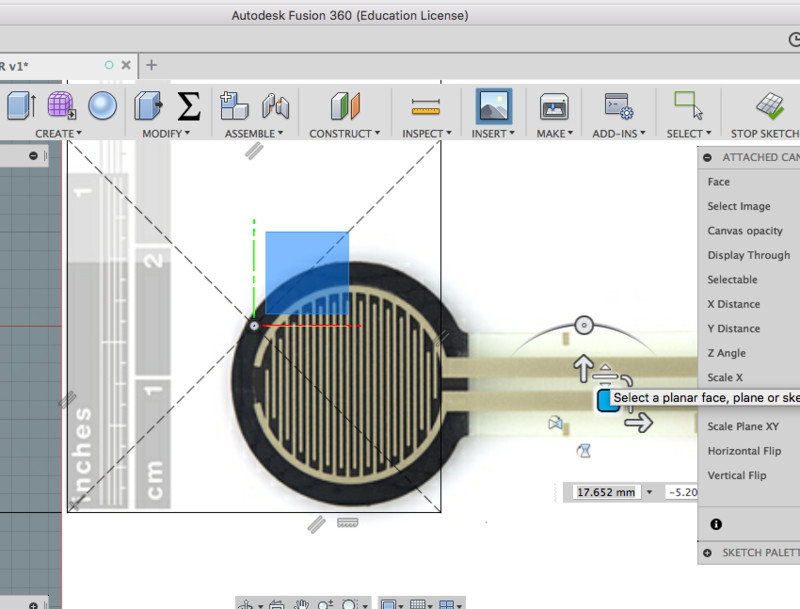
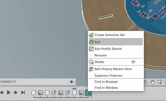
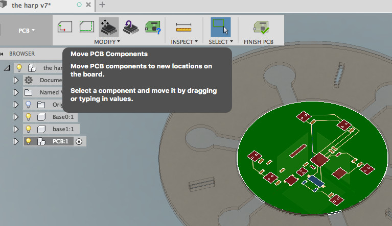
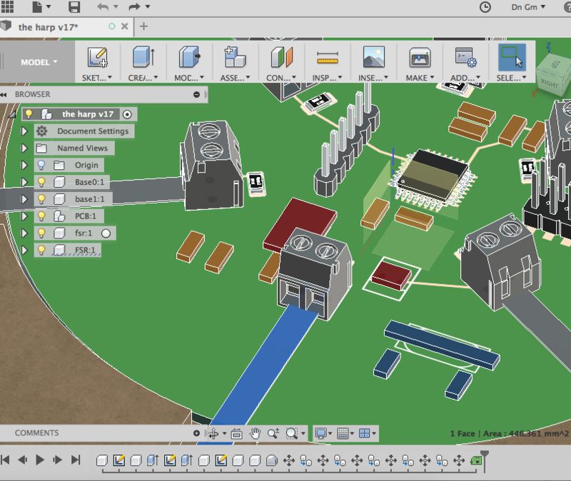
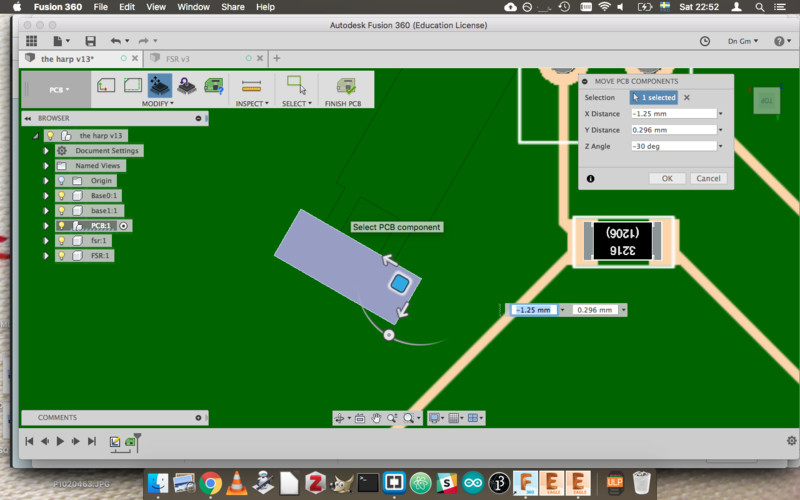
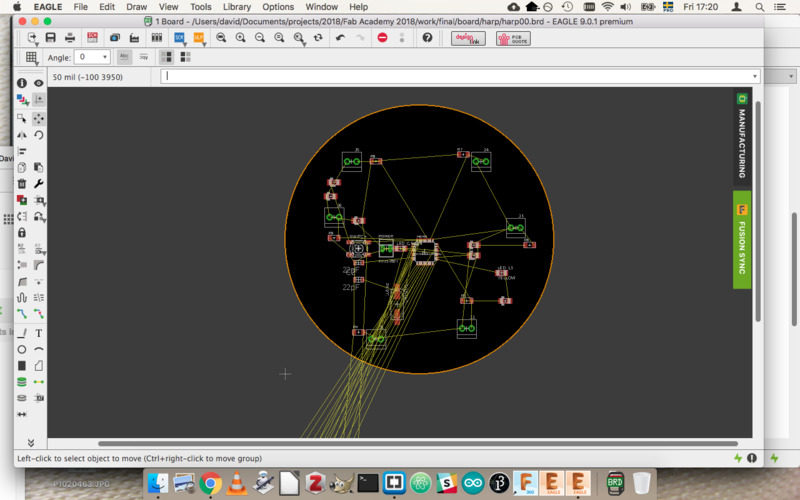
I experimented with Fusion and Eagle integration, with the hopes that this would help me place the FSRs on the board properly. It didn't go quite smoothly, but I was able to get things to line up pretty well. I won't know how well this will work until I try it in real life. I downloaded the image of the FSR from Sparkfun, and used it to create a basic component in Fusion. Then I was able to place that component in the Fusion model, and then, within Fusion, place the FSR mounting points on the PCB, which was then updated to Eagle. Voila.
Here I am tracing and extruding the FSR:
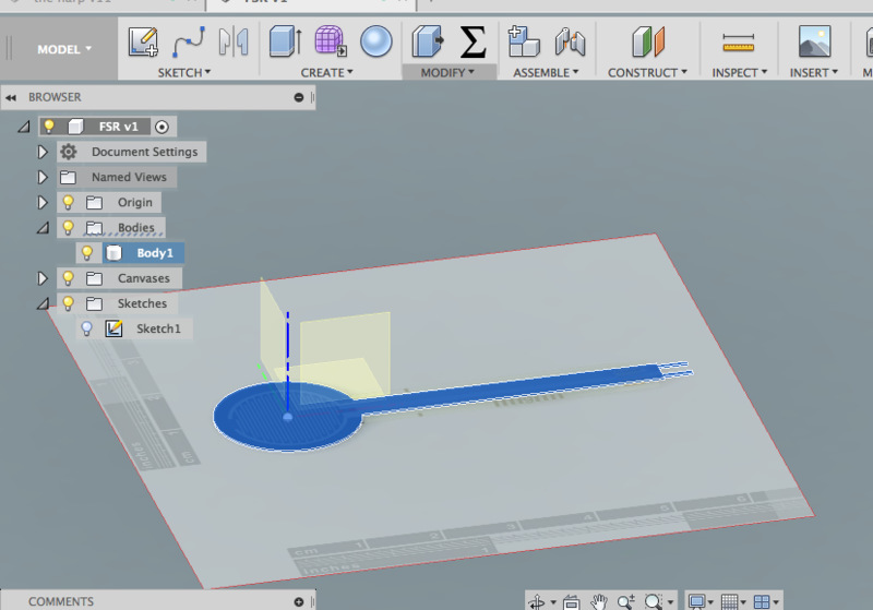
Here are some screenshots from the process of moving the PCB parts around in Fusion, and seeing the results in Eagle:
I followed the instructions from this series of Autodesk videos:
Most searches will turn up a tutorial from Adafruit on the integration, but it isn't nearly as thorough as the Autodesk videos.
The steps I took were these:
- Because my frame will determine the dimensions of the PCB, I chose to start from Fusion and import to Eagle (you can also start from Eagle and import into Fusion). First, in Fusion's preferences enable "PCB Feature" is enabled under "Preview".
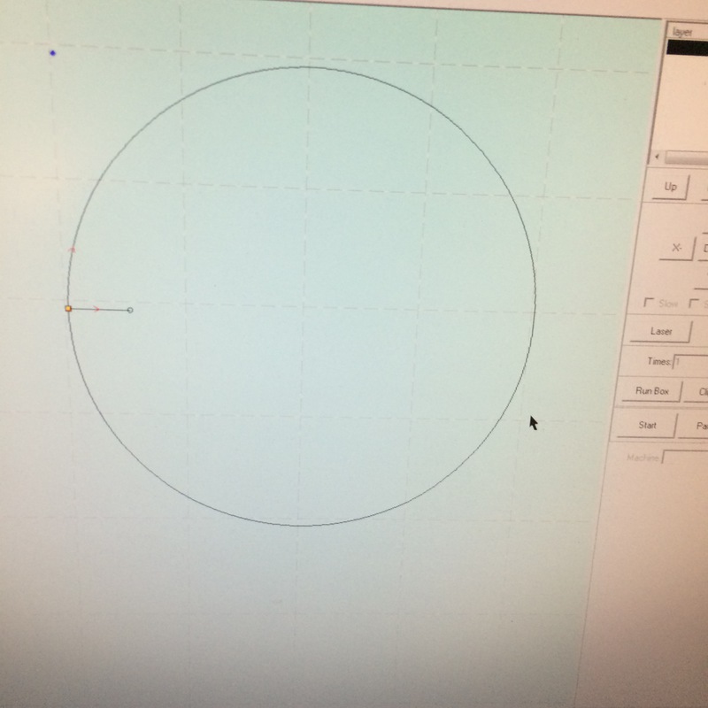
- In the model, I created a circle that I wanted to be the PCB, in the middle of the frame. Under the Create menu I selected "create PCB".
- Then I selected "finish PCB", and Fusion did some magic to make the circle a PCB.
- Then I saved the Fusion file.
- I navigated to my Fusion file in the window that was provided, and selected the PCB, and clicked OK.
- I clicked "Pull from Fusion", and voila, an empty circle appeared in Eagle.
- I then opened the Satshakit schematic, copied the schematic, and pasted it in the schematic for my Harp. The components then appear unrouted in the PCB view, but once I've modified the schematic for my project I can place and route the components.
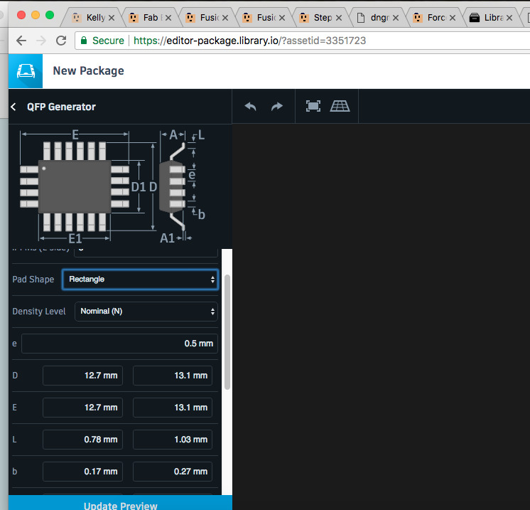
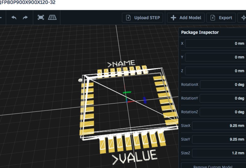
I even experimented with making some packages for the 3D model following the same instructions from the Autodesk videos. It was a waste of my time given the other more important things I needed to do.
2018-06-01
I've taken a look at my checklist of things that need to get done. I'm reassessing my priorities with the code. At the moment, I've decided on a behaviour where a rod pressed will trigger a behaviour. Ultimately, I want an expressive controller, maybe what a MIDI keyboard would term "aftertouch". For the time being, I will keep the interface as a trigger, and when everything is assembled I can work on developing aftertouch in the code.
I wrote a Python script to format a block of gcode into an array of strings for the Arduino. The code looks like this (warning, this code does not have characters escaped for HTML so may look weird, see the source for the proper characters):
gcodeFilename = "fannyFlower_layer_0.gcode"

def showNewGcode():

    print("char* gcode[] = {")

    with open("gcode/" + gcodeFilename, 'r+') as f:

        allLines = f.readlines()

        for line in allLines:
            gcode = line.strip('\n').split(' ')     # remove the carriage-return character, split it at the spaces into a list called gcode

            # enumerate over the items in gcode
            for thing in gcode:
                if 'E' in thing:    # delete the extrude commands (so no goo comes out)
                    gcode.remove(thing)

                if 'F' in thing:    # change the speed
                    #print("Original" + str(gcode))
                    tempSpeed = thing           # temporarily store the speed ocmmand
                    gcode.remove(thing)         # remove it from the gcode command
                    print ("\"G1 " + tempSpeed + "\", ")    # print it as its own command (this makes it easier for the arduino to analyse the incoming data)
            outstring = ' '.join(gcode)
            print ("\"" + outstring + "\", ")


    print ("};")

showNewGcode();
And it turns Gcode like this:
G1 F1200 X120.254 Y115.457 E0.00847
G1 X120.091 Y115.709 E0.02850
G1 X119.890 Y115.970 E0.05048
G1 X119.794 Y116.141 E0.06357
G1 X119.516 Y116.621 E0.10058
G1 X119.286 Y117.079 E0.13478
G1 X119.071 Y117.603 E0.17258
G1 X118.868 Y118.119 E0.20958
G1 X118.596 Y118.932 E0.26678
G1 X118.357 Y119.785 E0.32589
G1 X118.155 Y120.641 E0.38458
G1 X118.032 Y121.233 E0.42493
G1 X117.934 Y121.887 E0.46906
Into this…
char* gcode[] = {
"G1 F1200",
"G1 X120.254 Y115.457",
"G1 X120.091 Y115.709",
"G1 X119.890 Y115.970",
"G1 X119.794 Y116.141",
"G1 X119.516 Y116.621",
"G1 X119.286 Y117.079",
"G1 X119.071 Y117.603",
"G1 X118.868 Y118.119",
"G1 X118.596 Y118.932",
"G1 X118.357 Y119.785",
"G1 X118.155 Y120.641",
"G1 X118.032 Y121.233"
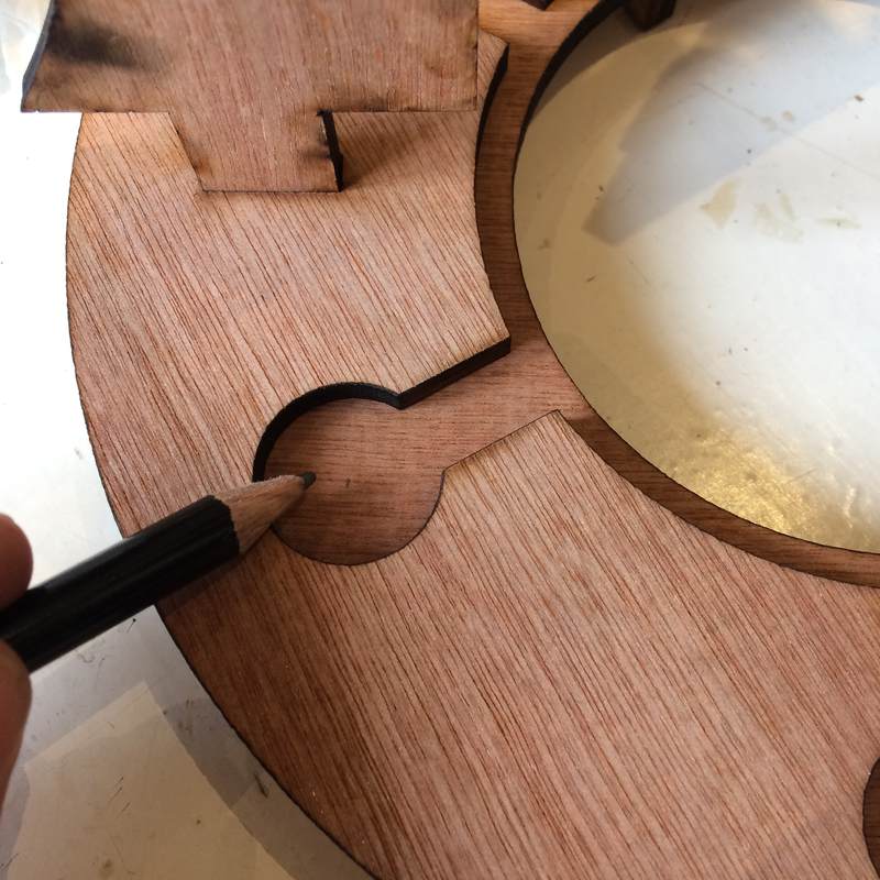
}I laser-cut a mockup in cardboard to see if the structure that I was planning was sound. It seemed to work fine, though I found that large supports made it difficult to reach the strings. Should I do other shapes? Other configurations? I decided not to argonise over it, so I redesigned the pillars to have a rounded cutout on the outside edge to make it easier to reach around them. Here is the initial model, and a redesigned pillar:
Here is apparently the exact same FSR as we have in the lab, though with no datasheet.
I read Autodesk's guide to integrating Fusion360 and Eagle, thinking that it would help with placement of the force sensors. I started modelling the base of the performance interface, and created a round section for the PCB, then in Eagle I was able to pull that in as a board design. Then I loaded the Satshakit Eagle files, and copied the schematic to my new, round schematic file. I added some screw terminals that will hold the FSRs, placed them around the circle about where I think the FSRs will need to be, and used the original Satshakit layout as a guide for where to place the passive components.
The ATMega328 has analogue-to-digital converters on pins 23-28 (Arduino pins A0-A5), so the FSRs will be connected to those pins.
I am going to place a 6-pin header on the board for the FTDI connection, which the satshakit does not have. I will need this for rapid debugging and code development.
2018-05-31
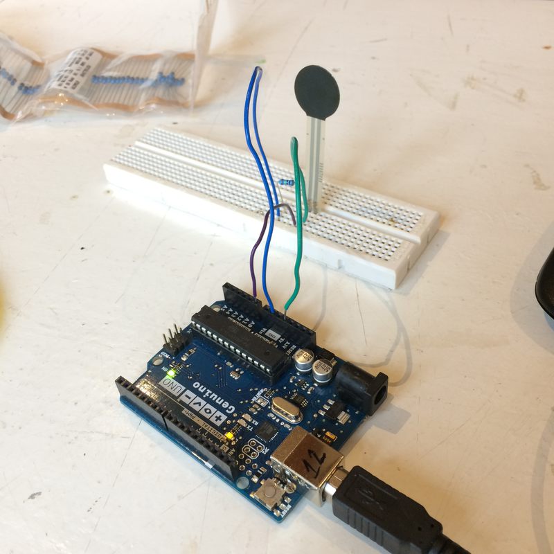
Checked Tom Igoe's Making Things Talk book for information on proper ways of handling serial communication with an Arduino. Read the datasheet for this force sensor to see if I could get physical dimensions and also what kind of resistance range I am looking at. It said 10MOhms when unpressed. I also read this Adafruit tutorial on how to use a force sensor.
I connected the force sensor in the same way as Adafruit specified. I tested several resistors, from 15k to 1M, and I liked the response of 15k best.
I was concerened that softwareserial on the attiny would not handle the default ultimaker baud rate of 250000, but this forum post seems to say that it should be fine.
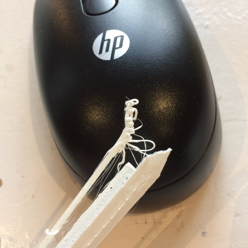
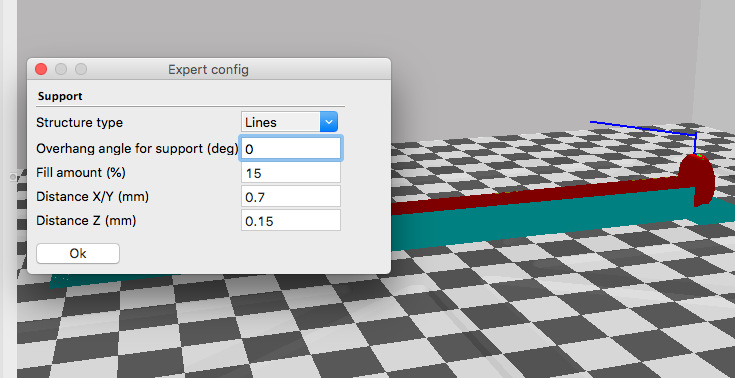
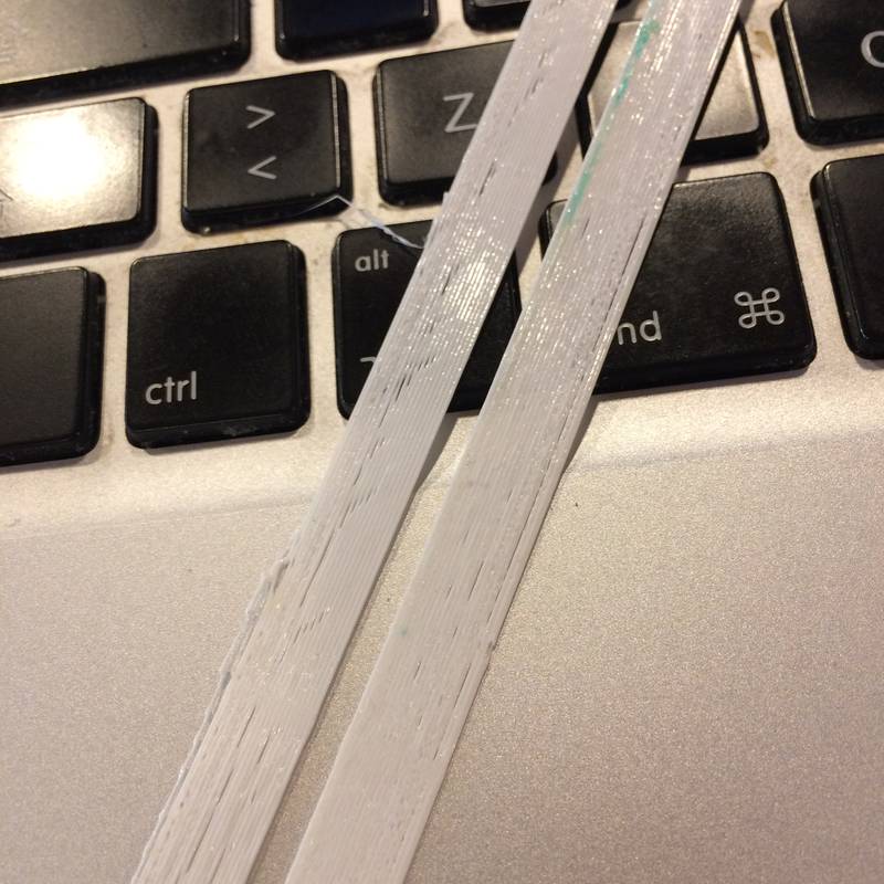
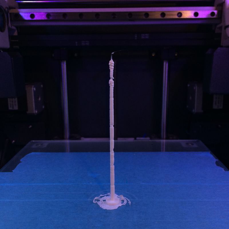
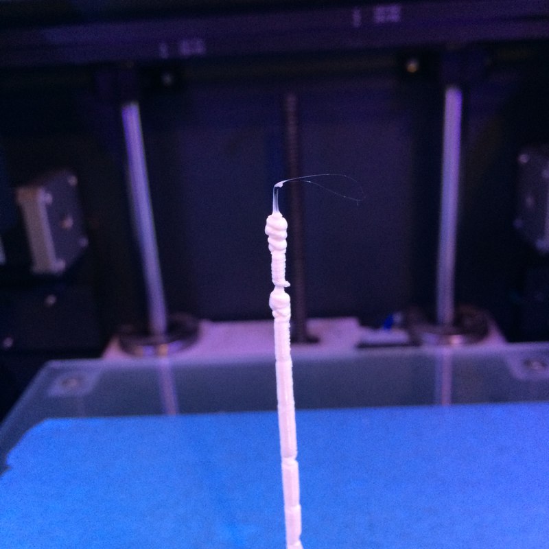
I tried printing the new tapered rod using PVA as a support material. I had worked with PVA yarns before in textile experiments, and was eager to try it in printing. I could not get the filament to stick to the bed or the PLA. I googled. I raised the bed to 60°C. Still nothing. I gave up and printed the whole thing in PLA, since the results were OK and would require minimal processing. Then because the rod was tapered, Cura decided not to print support material for the end of the rod (which I don't fully understand). It was terrible, so I changed the support parameters to support all surfaces (see the second image, 0° for the overhang). The result was great. The tapered rod supports more force without bending. The final image is a cancelled print where there should have been PVA support in the middle but nothing stuck.
My tests using the 3D printer played with the rod orientation and the support types and their settings, but did not change the print settings for things like speed and layer height. By the time I was able to achieve an OK result with the overhang settings and the support, I really only had time to print out the rods as they were while working on other aspects of the project. The settings used for the print were:
- Layer height: .1
- Shell thickness: .8
- Fill thickness: .6
- Fill Density: 20%
- Print speed: 50 mm/s
- Print temperature: 210°C
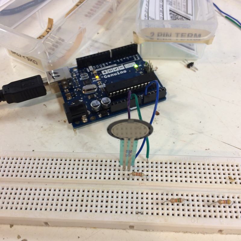
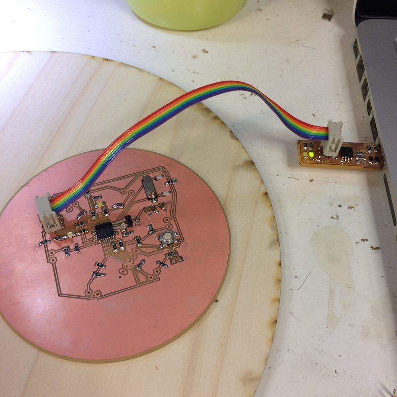
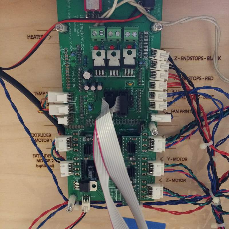
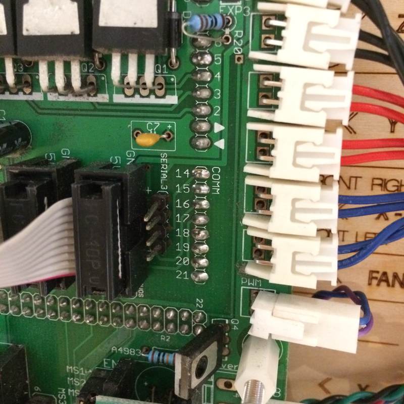
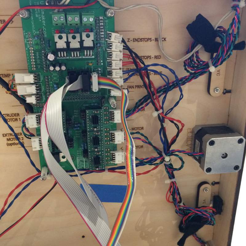
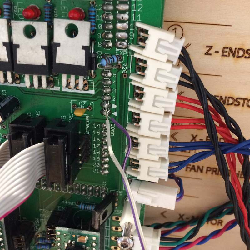
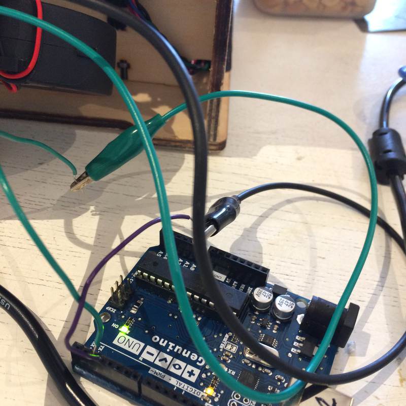
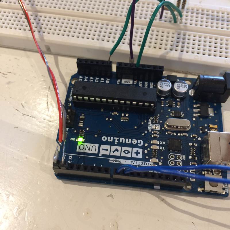
The Ultimaker controller board is listed as version 1.5.4, the documentation page says that there is serial access on it for peripherals, with no information on where it is exactly on the board. It lists a pinout of the exp1 port as having pins for TX1 and RX1, which means this is the second serial bus on the Arduino Mega that is controlling the Ultimaker, which is not promising because I assume that it is the first serial bus that handles the serial communication. There is also a link to someone who installed a Bluetooth module inside their ultimaker, but does not specify where they attached it onto the board. So, using software serial on the arduino, I try plugging into the exp1 port, and cannot get a response. I try plugging into the pins beside it labelled serial3, and get no response. After all this headache, I bite the bullet and solder directly to the TX and RX pins of the Arduino (accessible on the ultimaker controller board). Images: testing the force sensor, the bottom of the ultimaker board, a closeup of the pins and their labels, a rainbow ribbon cable trying to access serial3, grey and purple wires soldered directly onto the board, and alligator clips completing the connection to Arduino pins handling the software serial.
And… partial success. I get serial garbage! So, that's a step in the right direction. I try all kinds of baud rates. I google software serial and baud rates and someone suggests that the library altsoftserial is better, I try that with no luck. Then I go directly into pins 0 and 1 of the Arduino (the hardware serial pins), and echo that out through software serial to an FTDI cable pugged into the computer so I can see the results and … Success!
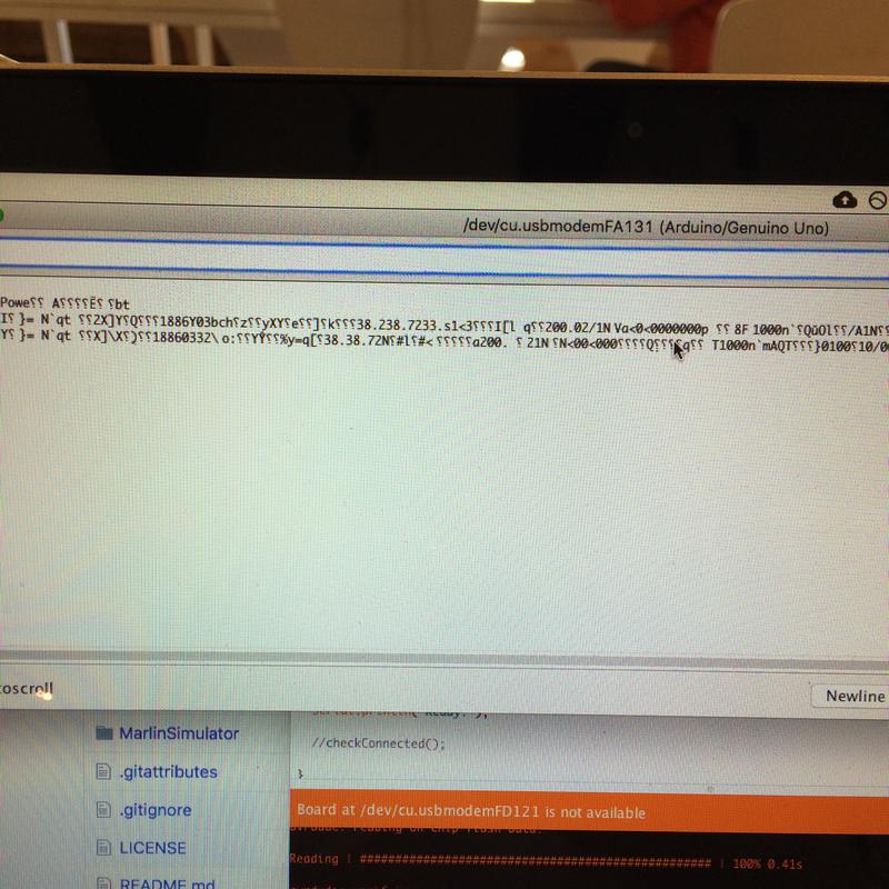
Finally, success. Software serial could not handle 250000, despite what forum posters said.
Also, the Arduino in the Ultimaker needs to be plugged in to work, which is stupid because it should just get power from the motor power supply. So I should also supply it with power.
For my own notes, the cable I soldered into the Ultimaker is coloured: red TX, brown RX
The serial data I get is this:
start
echo:PowerUp
 Brown out Reset
Marlin1.0.0
echo: Last Updated: Jul 23 2015 10:30:19 | Author: (David Braam)
Compiled: Jul 23 2015
ec3 Se 5o:50n90cl4Afvim==o20e0h echo:SD init fail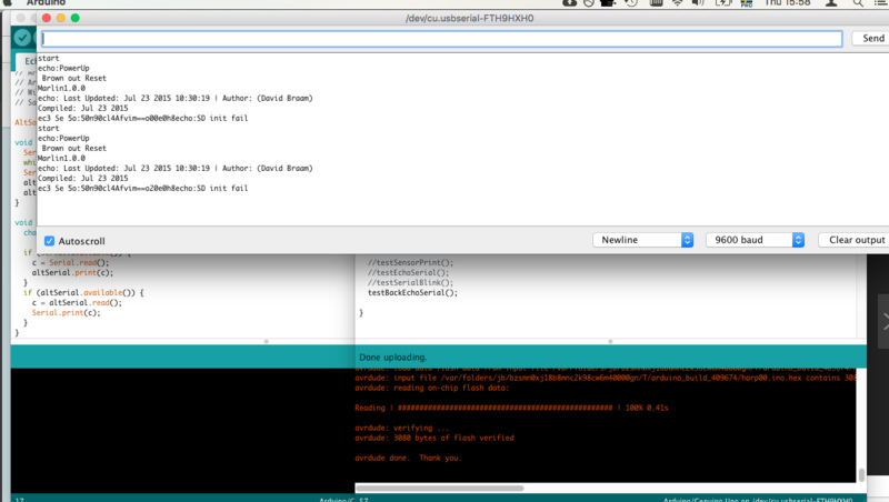
But I only get it if I plug in the Arduino after the motor power supply has already been plugged in and the machine is on. Oof. This is frustrating.
Now the Arduino acts as a bridge. From the Arduno serial monitor I can send gcode directly:
void testBackandForthSerial() {
  while (Serial.available()) { ser.write(Serial.read()); }
  while (ser.available()) { Serial.write(ser.read()); }
}
And it looks like this:
A new problem. I've noticed that the printer sends the "ok" before the move has been completed. I assumed that "ok" meant that the move was finished. Now I guess I need to construct some calculation based on the speed to guess when any particular command will be done.
I then adapted the force-sensor code and the printer bridge code as a test. When the sensor is squeezed, the print head moves to a random location:
Now that I have gotten a connection between the force sensor and the 3D printer, I need to find a way to massage gcode into a format that Arduino likes. I'll repurpose my older python code to do that.
2018-05-30
I wanted the rods to have surface texture to help in the performance, so I looked into Fusion 360 bump mapping. this forum post seemed to have the conclusion that Fusion 360 is not a good tool for it, and on further consideration I don't think that what I need produced is complicated enough for "displacement" mapping (as a forum poster termed it). I'll look for some kind of rectangular pattern and see if that can do what I need.
Today, print some test rods for proportion?
Also, I did a quick ideation exercise with the dice again (from week 0) to see if I really wanted to do the harp interface.
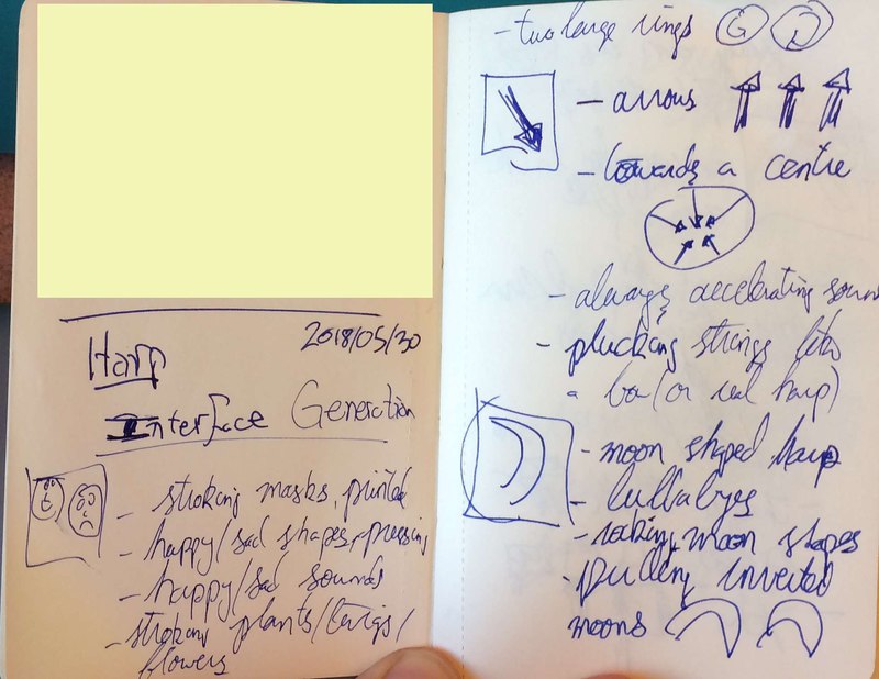
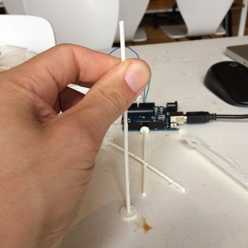
I 3D printed several test rods. One was printed vertically, and it had all kinds of weird artefacts that I could bug fix, but I don't want to. So I printed horizontally with supports. It printed fine with minimal artefacts that can be dealt with with post processing. I tested two heights, 10 cm and 20 cm. The 20cm bends in ways that I think might be difficult. This can be fixed by maybe increasing the base size, and also maybe creating the rods as slight cones, thinning as they go up.
Todo, check fusion360-eagle integration.
2018-05-25
Connecting to the printer using serial works. I get "ok" back when sending commands. I used screen -L /dev/cu.usbmodem12341 115200 -L in the shell.
Resonator on the printer to amplify the sound?
Success! I can send it bits of gcode. I can change the speed. The speed change is interesting.
2018-05-24
Because my code will need to modify the speed of the gcode progressively, it cannot send the code in a block. I thought then that I needed to send each line at a time, and needed to know how long each command would take to determine when the next should be sent. I tried looking at the E999.999 argument of the G1 command, which controls extrusion, which I thought would have a linear correlation with the distance travelled, which is a proxy for time. Nope! Some spreadsheet calculation returned numbers that did not match. so… I remembered actually that the printer sends OK when it's ready for a new command. So, new version, just read the serial and wait for OK before sending the next line. Genius.
Do I need the pronterface library? Could I instead just use an arduino? Or the chip directly? The printer is a USB device, likely through FTDI, so I need a device that can communicate with FTDI. Arduinos can do that with the USB Host shield. Do I go down that route? For it to work, I need to be able to communicate with the serial port without using the library. Can I?
2018-05-04
I'm looking at a basic tkinter interface just to see how it would be to modify the speed modifier on the fly. This is leading me down some dependency hell, but I'm getting there…
I need to rapid prototype parts of this as soon as possible. I'm making the assumption that changing the speed of 3D printing gestures will be interesting. I have no idea. Test the same gestures as different speeds to see if it's interesting.
Interface: I'm trying to keep it simple now. Sliders? Basic tutorial: https://www.python-course.eu/tkinter_sliders.php
2018-05-03
I looked at various pthong libraries for parsing gcode. All of then seemed way to heavy for what I needed (to change speed). I found gctools, which seemed to be uncomplicated, but I ran into dependecy hell. So I decided to make the code myself, since I didn't need it to do so much. So far…
# GCODE notes, E is for EXTRUDE, F is the moving speed

multiplier = .333     # how much to change the speed


gcodeFilename = "gcodeSnippet.gcode"

with open(gcodeFilename, 'r+') as f:

    allLines = f.readlines()

    for line in allLines:
        gcode = line.strip('\n').split(' ')
        for thing in gcode:
            if 'E' in thing:    # delete the extrude commands (so no goo comes out)
                gcode.remove(thing)
            if 'F' in thing:    # modify the speed
                print gcode
                gcode[gcode.index(thing)] = thing[:1] + str((float(thing[1:]) * multiplier))
        print gcode
Also, I wondered how complicated what Pronterface is doing, and whether or not I could just send the GCode directly over serial. Some googling showed that printrbot is actually using FTDI inside to create the serial connection with the computer. So I started thinking about whether I could bypass the raspberry pi and do the whole thing with an ATTiny. The question is, can the ATTiny be a USB host? Or, can I bypass the FTDI chip on the printer? (I don't think I'll be allowed to do this). Using the tiny as a USB host looks difficult, but there is an Arduino shield to act as a USB host. I could use the shield with an Arduino, and to satisfy the course requirements I make my own board for the sensor inputs. Also, I could maybe just use the chip from the board with a Tiny. Will have to see…
Some posts about timing and sending multiple messages over serial: http://forums.reprap.org/read.php?156,547845 and http://forums.reprap.org/read.php?12,258823
It may be that the Pronterface library handles flow control, but forums discussing gcode over serial say that this can be a problem. If I want to then try doing it with an Arduino, this may be a problem. One poster wrote that waiting for "ok" leads to erratic behaviour, but I'm not sure of how else to do it.
… just read that apparently pronterface handles this flow control problem.
2018-05-3
Again I asked Troy about sending live data to a 3D printer. He cryptically mentioned Marlin and Pronterface.
Started reading about Marlin, apparently the firmware on both the printrbot and the Ultimaker. This converts the gcode into printer actions. Maybe I can work directly with it.
I also looked at pronterface, which is actually a suite of different tools that I might be able to use to control the printer.
Using macports: install python36, py36-appdirs, py36-serial, py36-pip, py36-pyobjc
and "port select --set pip pip36"
After getting frustrated with dependency hell, I found that printcore.py runs just fine. AND I can send data to the machine! So now, I think I reevaluate my weekly assignment for interface, and instead focus on python getting serial data from the Arduino. To connect do:
#to send a file of gcode to the printer
from printrun.printcore import printcore
from printrun import gcoder
p=printcore('/dev/tty.usbmodem12341',115200) # or p.printcore('COM3',115200) on Windows
And then send gcode commands directly with p.send_now("G21"). In action:
Sending gcode directly. from David McCallum on Vimeo.
I have been envisioning "playing" sequences of GCODE, and changing the expression by changing the speed of the motor movement. After reading the rerap gcode wiki it appears that the machine interpolates between coordinates. So, how does it determine the speed of the movement between the points?
Got it. This was unclear to me before. The F argument in G1 sets the speed of travel. I thought it set the feedrate, so I didn't understand what the E feedrate setting was doing. So… I can take existing movements, and scale the F argument… now I have to test it.
2018-04-18
I decided to spend a few minutes focussing on the expressions of the printer, and just recorded a minute of video of the printer making a ukulele mounting hook I designed. What I would like to see, like I can see in the Shoptbot software, is a live readout of which parts of the gcode are being executed.
3d printing noise from David McCallum on Vimeo.
I also worked with a stepper motor to see what it's like to control directly in week 12.
2018-04-04
I chatted with Emma about the requirements of the final project. I was concerned that my concept for the final project doesn't require some of the techniques that the final project required. If I'm going to perform a 3D printer, what need is there for, say, an output device? Would it be OK if I connected a blinky LED just to satisfy the requirements of the final assignment, even though it really has no place in the project? I still think that if I'm writing algorithms to GCODE to communicate with a machine, then that's functionally the same as sending commands to other digital actuators (like, say, a motor driver). Emma says fine, I can put a blinky LED if it's integrated.
Emma suggested I build one axis of a 3D printer with a stepper motor, but that ruins the conceptual aspect of the project, that the machine itself is the instrument.
So what is the input? I've decided to try capacitance sensors. I've always been curious about them, and I wonder if perhaps I could use some of the metal in the 3D printer as the antenna. And then, what if the machine's movement affects the capacitance reading? What if I generate a recursive behaviour? The machine plays itself?
I can envision two controller inputs. If I compile a collection of code for different sound expressions, then one input is discrete, controlling which expression is being played. The second input is continuous, controlling qualities of the expression (though, for example, speed of travel of the machine head).
2018-03-21
Troy sent me a link to this tutorial from Makezine about GCode. I'll review this next and see what kind of clarity it can give me.
2018-03-07
I spoke to Troy Nachtigall—who writes algorithms to write gcode to generate shoe—about live control of 3D printers. He said something about needing to send four commands at a time to the machines, and we discussed how to make that more immediate, such as sending intermediate coordinates instead of final coordinates.
2018-02-28
Tomorrow is St. David's day! I examined one of the .gcode exports from the Week5 assignment. Cura is very nice at commenting the code to state what each command does. And the RepRap wiki GCODE page was great for explaining further what each command does. I think that I will need to create some basic GCODE files to test how the printer responds. Code example:
M109 S210.000000
M190 S0.000000
;Sliced at: Wed 28-02-2018 16:07:12
;Basic settings: Layer height: 0.15 Walls: 0.8 Fill: 20
;Print time: 17 minutes
;Filament used: 0.194m 1.0g
;Filament cost: None
;M190 S45 ;Uncomment to add your own bed temperature line
;M109 S210 ;Uncomment to add your own temperature line
G21        ;metric values
G90        ;absolute positioning
M82        ;set extruder to absolute mode
M107       ;start with the fan off
G28 X0 Y0  ;move X/Y to min endstops
G28 Z0     ;move Z to min endstops
G1 Z15.0 F9000 ;move the platform down 15mm
G92 E0                  ;zero the extruded length
G1 F200 E3              ;extrude 3mm of feed stock
G92 E0                  ;zero the extruded length again
G1 F9000
;Put printing message on LCD screen
M117 Printing...

;Layer count: 106
;LAYER:0
M107
G0 F9000 X112.615 Y112.974 Z0.300
;TYPE:SKIRT
G1 F1200 X114.328 Y111.565 E0.04086
G1 X116.155 Y110.713 E0.07799
G1 X117.974 Y110.292 E0.11238
One of the next steps will be seeing how I can go from a static GCODE file to directly controlling the machine. This seems relatively straightforward for the Printrbot, which already requires a direct connection from the computer. I'm not sure how to do that with the Ultimaker or the BCN3D. Perhaps I will limit myself to the Printrbot in the beginning.
The sound of different fill patterns? Use them as expressions? Change pitch?
The original proposal description: performing the machines
This proposal is to use the digital fabrication machines, to create an interface (or interfaces), to control the machines live so that they can be performed like instruments.
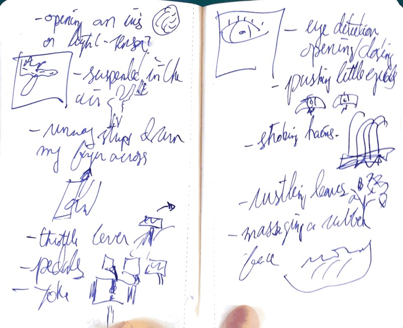
This would require the creation of a physical interface, using either casting, cutting or printing. The interface would depend on what can be controlled of the machines, but could be traditional sliders and knobs, or accelerometers, computer vision, photo resistors, IR proxmity sensors, etc. There are no sketches for this. This proposal requires learning how to use the machines before I can fully formulate a proposal for how the interfaces would work with a performer.
There is a long history of machines being used for music, look at industrial music and the breadth of experimental music. There is also a history of automated machines being repurposed for music, like floppy drives, tesla coils, and 3D printers.
I'm interesting in something a little more subtle. Maybe using a more nuanced PWM, something more organic, but there are all kinds of noises that machines make, not just in the manipulation of the motors, and its through using these machines that I hope to uncover what these performance opportunities are.
The physical interface depends on what's being controlled. Is it a traditional MIDI slider box? Michel Waisvisz' The Hands? There is a range of possibilities, and this can't really be planned out this early in the process.


The other proposals
I did an extensive ideation exercise to generate ideas. They're available on the Week 0 page. Here are the two most viable…
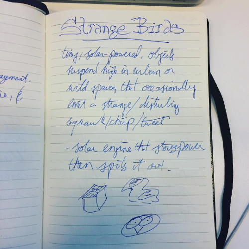
Proposal 1: Strange Birds
Small objects suspended high in either natural or urban environments. They contain a solar engine and a speaker. When the engine has collected enough energy, the Strange Bird emits a very strange, not-quite birdlike squawk. I often find myself looking straight ahead or down, and am always amazed at the world above me. This objects are intended to get passers-by to look up. The solar engine needs testing to make sure that the timing of the squawks is not too rapid.
The form is uncertain. It could be natural-looking (a bird, a branch), or artificial, such as a plain cube. It would be cut or casted. The electronics require a solar engine, microcontroller, and audio driver and speaker.

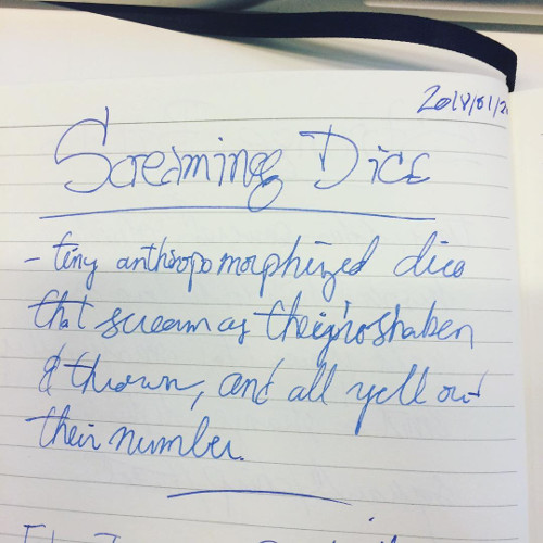
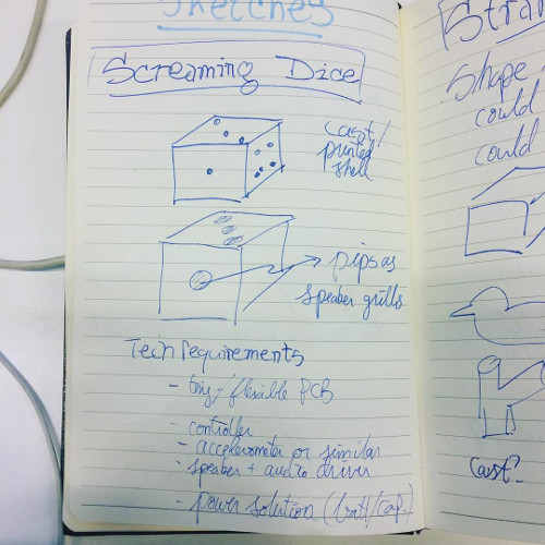
Proposal 2: Screaming dice
Tiny anthorpomorised dice. They look like regular game dice, but act like little people. Each die mumbles when shaken in the hand, screams when thrown, and yells out its value when it lands. The user is uncertain, game players? Perhaps yahtzee and backgammon?
The pips could act as speaker grills. The form would be cut or casted, the guts require a tiny or folded PCB, a microcontroller, some kind of accelerometer, an audio driver and speaker, and a power solution.