Week 10: Input devices
Download this week's code
- Knowing Me Knowing You schematic and board files for Eagle
- Fernando schematic and board files for Eagle
- Arduino sketch for reading the numbers
Assignment requirements
The first checklist
- Measure something: add a sensor to a microcontroller board that you have designed and read it.
The second checklist: Learning outcomes
- Demonstrate workflows used in circuit board design and fabrication
- Implement and interpret programming protocols
The third checklist: Have you…
- Described your design and fabrication process using words/images/screenshots.
- Explained the programming process/es you used and how the microcontroller datasheet helped you.
- Explained problems and how you fixed them
- Included original design files and code
Final project
I chatted with Emma about the requirements of the final project. I was concerned that my concept for the final project doesn't require some of the techniques that the final project required. If I'm going to perform a 3D printer, what need is there for, say, an output device? Would it be OK if I connected a blinky LED just to satisfy the requirements of the final assignment, even though it really has no place in the project? I still think that if I'm writing algorithms to GCODE to communicate with a machine, then that's functionally the same as sending commands to other digital actuators (like, say, a motor driver). Emma says fine, I can put a blinky LED if it's integrated.
Emma suggested I build one axis of a 3D printer with a stepper motor, but that ruins the conceptual aspect of the project, that the machine itself is the instrument.
So what is the input? I've decided to try capacitance sensors. I've always been curious about them, and I wonder if perhaps I could use some of the metal in the 3D printer as the antenna. And then, what if the machine's movement affects the capacitance reading? What if I generate a recursive behaviour? The machine plays itself?
Research
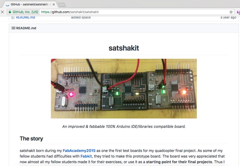
I was curious about making a fabduino or satshakit, so I took a look at the satshakit github page to see what was required. It didn't seem any more complicated than the echohello board, except that the IC soldering looks more finicky, but that seems like a good skill to acquire. So I'll make some version of the satshakit board with a sensor designed into it.
After talking with Emma, I changed my mind. I decided to make a general-purpose version of the helloEcho board with pins breaking out the connections so that I can connect sensors. Again, keep it simple given the limited time.
I took a look at the capsense Arduino library, and specifically if it worked with the ATtiny chips. It appears that it does.
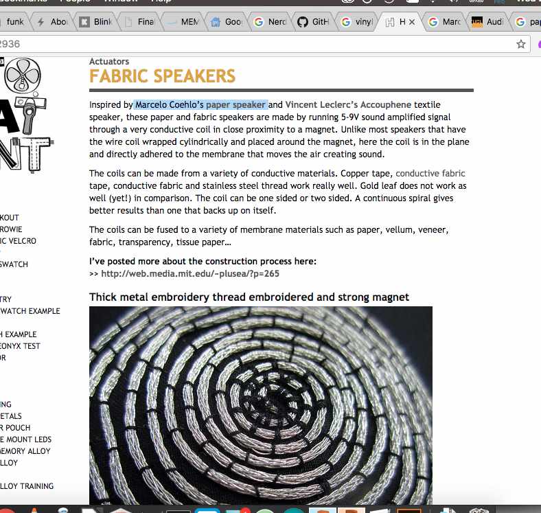
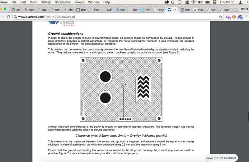
I also took a look at How to get what you want, an extensive resource of DIY sensor and actuator information, with much pertaining to soft textiles and conductive fabrics. I was interested in maybe taking an existing weaving that I bought from a flea market and making parts of it active, perhaps by embroidering conductive thread behind parts of the image and sensing the proximity of a hand. (Why? Why is an embroidery supposed to be touched? How is that a logical interaction method? Yeah well, why not.) Kobakant linked to two interesting documents dicussing good practice when designing capacitance sensors. this one and this one. Still, as usual, I think I'll start sloppy with the technology design and refine it as I need to.
Making
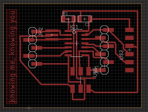
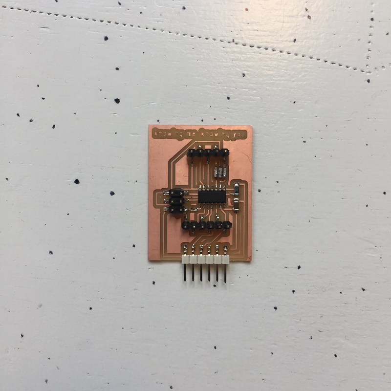
I took my previous helloEcho board schematic, and removed all of the sensors. I then added two rows of single SMD headers. I originally tried to add a single, long row, but found that I ran into routing problems, so I broke it down to 5 and 6 pins, on either side of the chip. I searched for solutions to find a library with parts for these kinds of headers, and found the pinhead-2 Eagle library, which is full of all kinds of header footprints, through-hole and SMD.
I decided, after Henk and I got our helloEcho boards mixed up TWICE, that I would personalise the boards. So now, each of my Fab boards will have the title of an ABBA song engraved in the copper. This one is called Knowing Me, Knowing You ("there is nothing we can do…"). I wanted to do Kiss the Teacher, but I thought Emma might get worried.
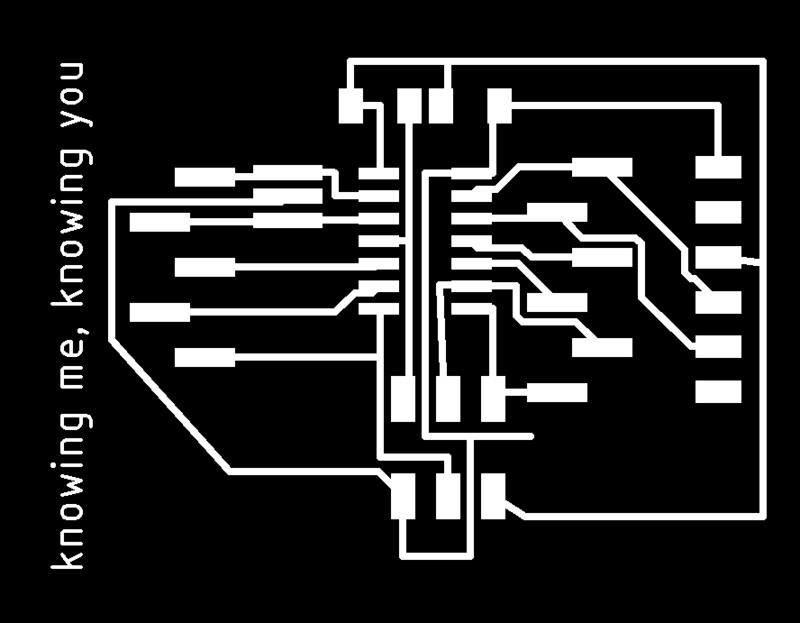
The board was milled on the Roland MDX-20 as per the routine outlined in week 4. Here are the PNGs used to etch.

After milling and populating the board, I adapted one of the examples from the Capsense library, used Software serial for communication, and decided to see if I could read any pins. Surprisingly enough, holding an SMD resistor between the pins generated data! I didn't use the datasheet for this, but I did use pinouts to determine which pins could be used for the sensors.
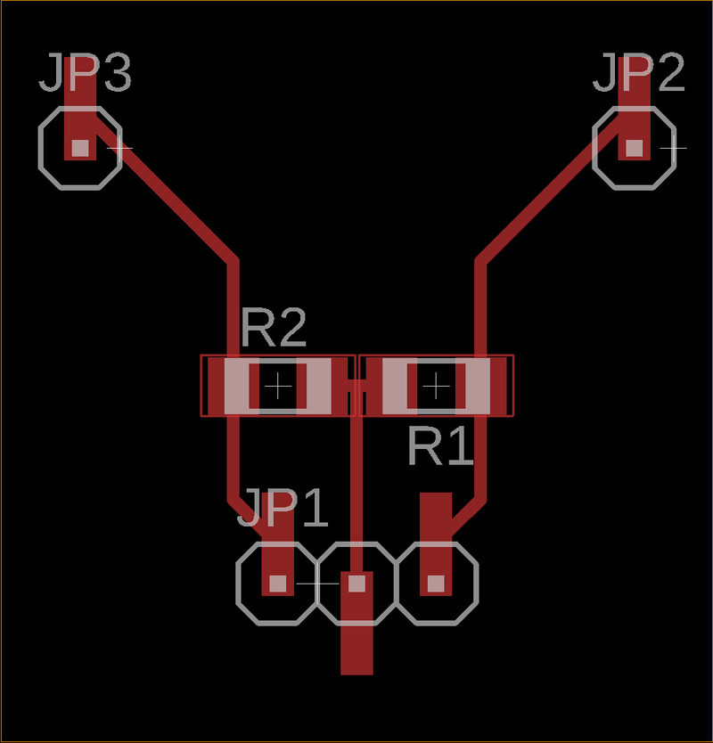
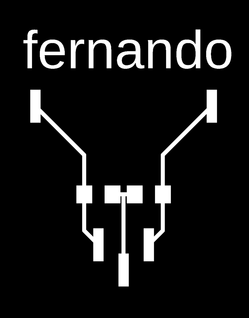
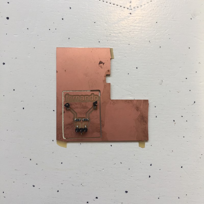
I realised that this was going to be impractical. So I quickly modelled a breakout board with two high-value resistors, headers to connect back to Knowing Me, Knowing You, and two headers for connecting to antennas or objects with alligator clips. And because I'm now an Eagle and milling expert, I did the whole thing in less than 20 minutes. Here are the PNGs for the capacitance breakout board, and the board itself. I called it Fernando.

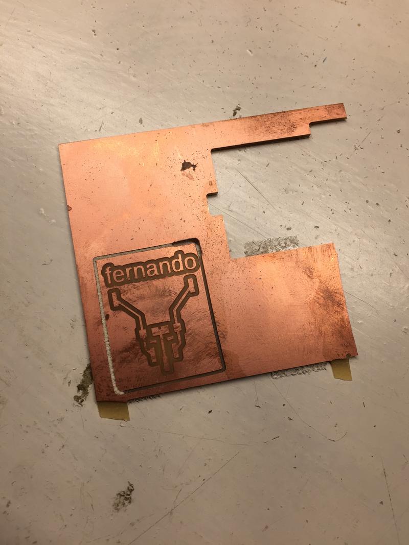
And why the weird shape and the terrible cutting job? Midway through cutting the board out I heard a strange sound, and saw the board spinning around the bit. I immediately turned off the machine and removed the board. Somehow the double-sided tape got loose from the sacrificial layer. I should have cleaned the sacrificial layer with a cleaning agent before putting on the tape. I decided to leave that extra copper. I can be one of the antennas if I want it to. I had already wondered whether I should have put big copper pads on the board to act as antennas, but didn't do it because I had limited time and didn't want to figure it out in Eagle. That will happen some other week.
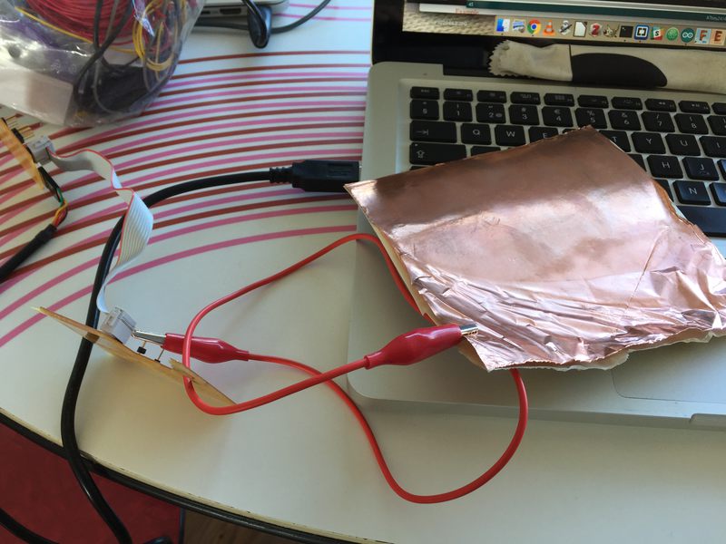
Here are pictures of each of the boards, and both of them connected with a ribbon cable, and two alligator clips ready to be clipped to something. Don't they kind of look like a heart?
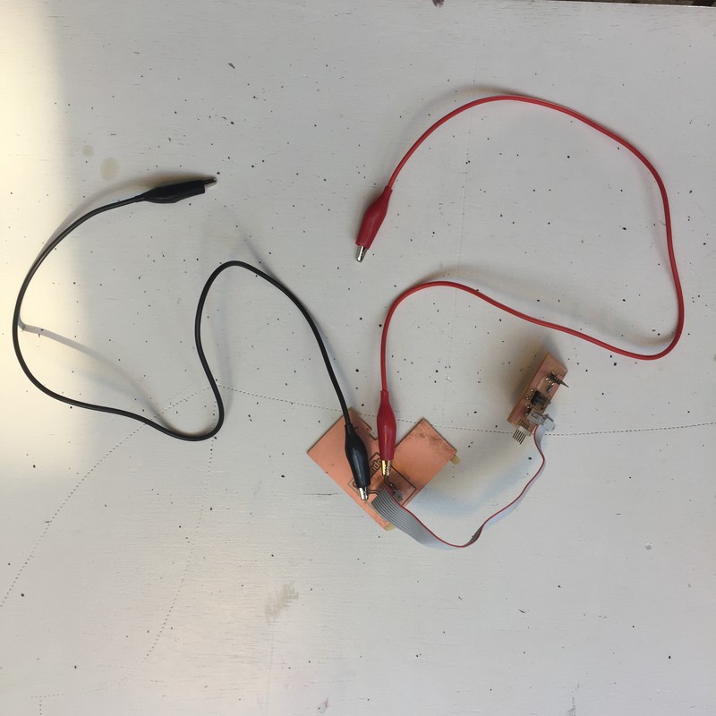
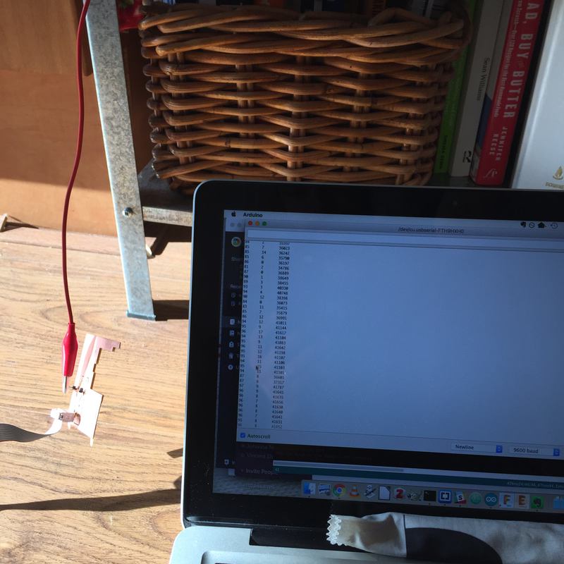
I connected the two boards with a ribbon cable, and after some experimenting with cable orientation to make sure I connected it correctly, I got data! Here is the output from the serial connection of me alternately tapping each of the header pins. The first column is the timing in milliseconds between measurements, the second column is the value from the first sensor, and the third column is the value from the second sensor.
Timing	s1	s2
103	45577	98
27	7831	48
12	20	31
11	21	37
11	27	36
10	22	41
12	76	586
54	142	21306
72	152	30669
11	15	39
10	6	29
12	16	26
12	7	41
11	18	32
118	53383	115
30	9509	25
10	24	48
10	26	35
11	26	47
12	22	43
35	115	11603
35	118	11996
34	128	11379
18	113	3605
11	15	34
11	32	37
11	20	53
10	14	36
93	40891	82
67	28214	52
11	25	39
11	24	39
11	36	53
12	18	39
89	127	38786
92	149	40322
11	20	54
10	8	57
An interesting behaviour is the slight change in numbers on one pin when I touch the other. Why is that? Proximity?
I then went home from Amsterdam, and it turns out that I didn't have my programmer with me, so I couldn't upload any new code to the board, but I did use alligator clips to test different things as antennas. Each of these objects gave similar responses, with different number ranges. Implementing any of these would involve considering things like magnetic and electrical isolation and grounding to clean up the signals.
Here is the code that I wrote and adapted:
/* Capacitive sensing test code.
 *  Fab Academy 2018 at the Waag in Amsterdam.
 *  Copyeverything, David McCallum, 2018
 *  sintheta.org
 */


#include <CapacitiveSensor.h>
#include <SoftwareSerial.h>
#define rxPin 0
#define txPin 1

const int capMax = 11000;
const int capMin = 0;


SoftwareSerial serial(rxPin, txPin);

CapacitiveSensor   cs_4_3 = CapacitiveSensor(4,3);        // 10M resistor between pins 4 & 2, pin 2 is sensor pin, add a wire and or foil if desired
CapacitiveSensor   cs_4_5 = CapacitiveSensor(4,5);        // 10M resistor between pins 4 & 2, pin 2 is sensor pin, add a wire and or foil if desired


int a = -1;

void setup() {
  // put your setup code here, to run once:

  serial.begin(9600);
  cs_4_3.set_CS_AutocaL_Millis(0xFFFFFFFF);     // turn off autocalibrate on channel 1 - just as an example
  cs_4_5.set_CS_AutocaL_Millis(0xFFFFFFFF);     // turn off autocalibrate on channel 1 - just as an example


}

void loop() {
  // put your main code here, to run repeatedly:


    long start = millis();
    int total1 =  cs_4_3.capacitiveSensor(30);
    int total2 =  cs_4_5.capacitiveSensor(30);

    total1 = map(total1, capMin, capMax, 0, 10);
    total2 = map(total2, capMin, capMax, 0, 10);
    total1 = constrain(total1, 0, 10);
    total2 = constrain(total2, 0, 10);


  // Print numbers

    serial.print(millis() - start);        // check on performance in milliseconds
    serial.print("\t");                    // tab character for debug windown spacing

    serial.print(total1);                  // print sensor output 1
    serial.print("\t");                    // tab character for debug windown spacing

    serial.print(total2);                  // print sensor output 1

    serial.println();

    delay(10);                             // arbitrary delay to limit data to serial port


}
The library requires that you create a CapacitiveSensor instance, and this specifies the pin that sends the pulse, and the pin that reads it. In my case, pin 4 is specified each time for the pulse, because the same pin can be used for the pulse, and I used pins 3 and 5 as sensors. This is handy, so that the common pin was sitting in between the two sensor pins.
The methods for autocalibrating, set_CS_AutocaL_Millis(0xFFFFFFFF). Were confusing. I didn't compare enough what the results looked like with or without, and I could find no documentation online for how exactly they worked. I kept them in since I could work with the numbers that I was getting.
The method .capacitiveSensor(30) is the commands that reads the sensor. The number is the number of samples that the code takes to create a reading. A higher number is more accurate but takes longer. This is a problem if the entire code is waiting for this process, a better solution might be to have the sensors running on their own processors (like each has their own Attiny45).
In the output above, you'll see that the timing increases when the sensor value is higher (my hand is closer). Why is this? I am not sure, but I imagine that it has something to do with the capcitance of my hand increasing the amount of time for the step response. This means that the more the capacitance is affected, the longer it takes to reach the desired number of samples.
Copper foil!
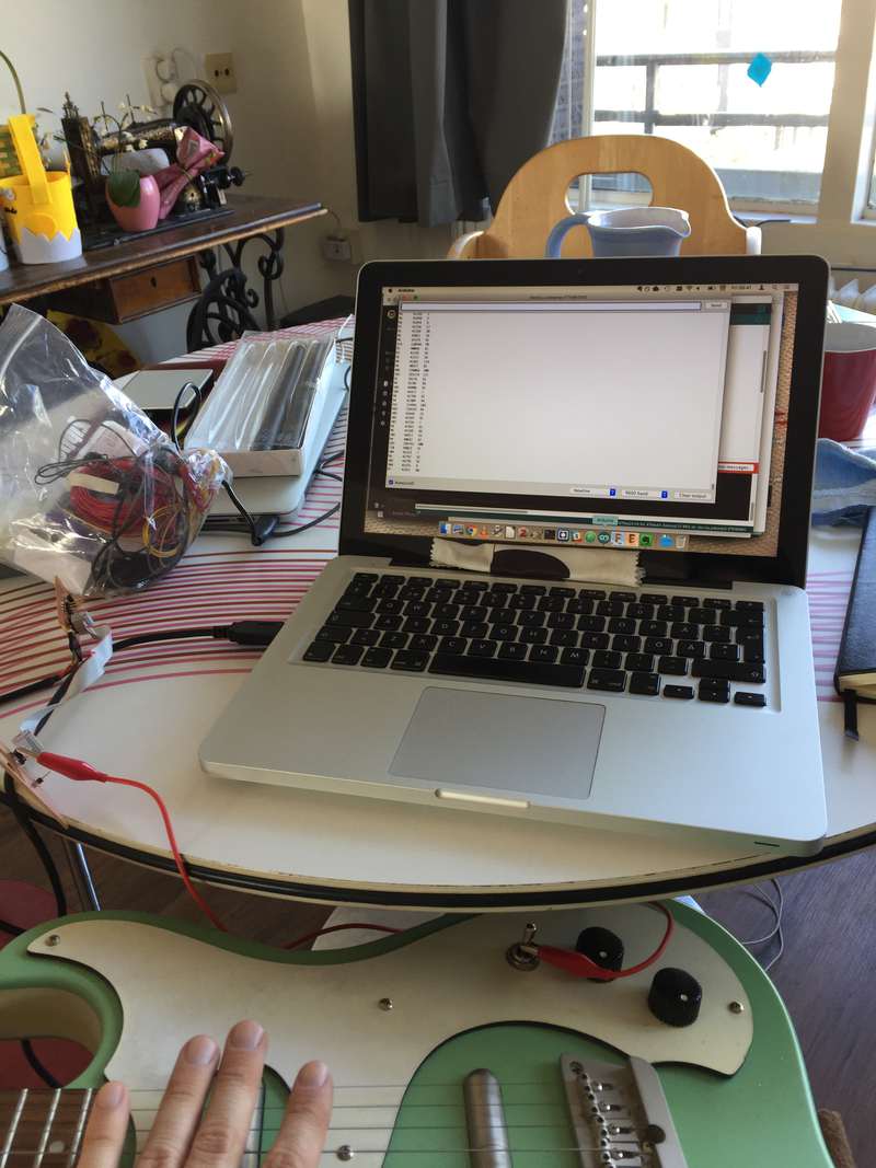
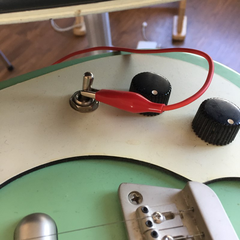
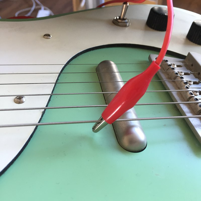
My guitar! Attached both to the pickup switch and the strings (all of which are grounded). Combine this with Xavier's tilting guitar and we're in business.
The cheap metal Ikea shelves in my kitchen! (That book with the red spine is Make the Bread, Buy the Butter, a cookbook I wholly recommend if you like making food basics from scratch.

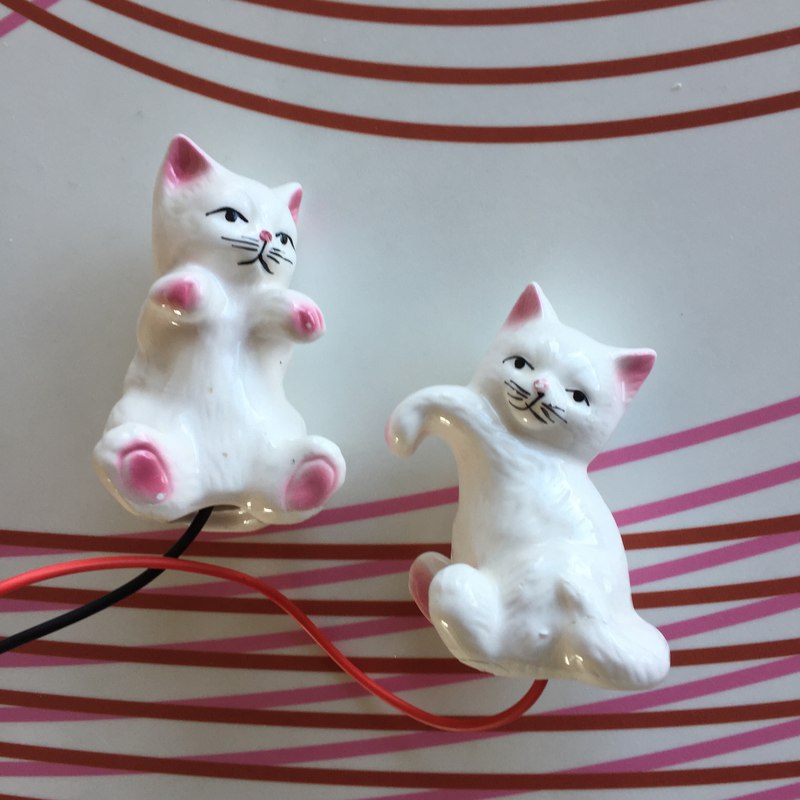
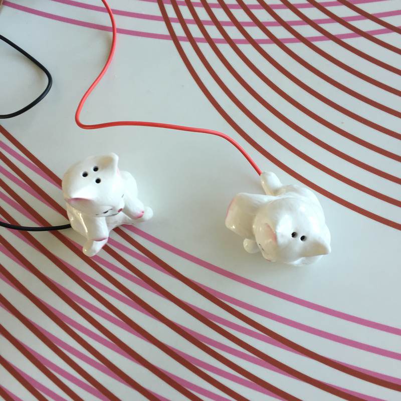
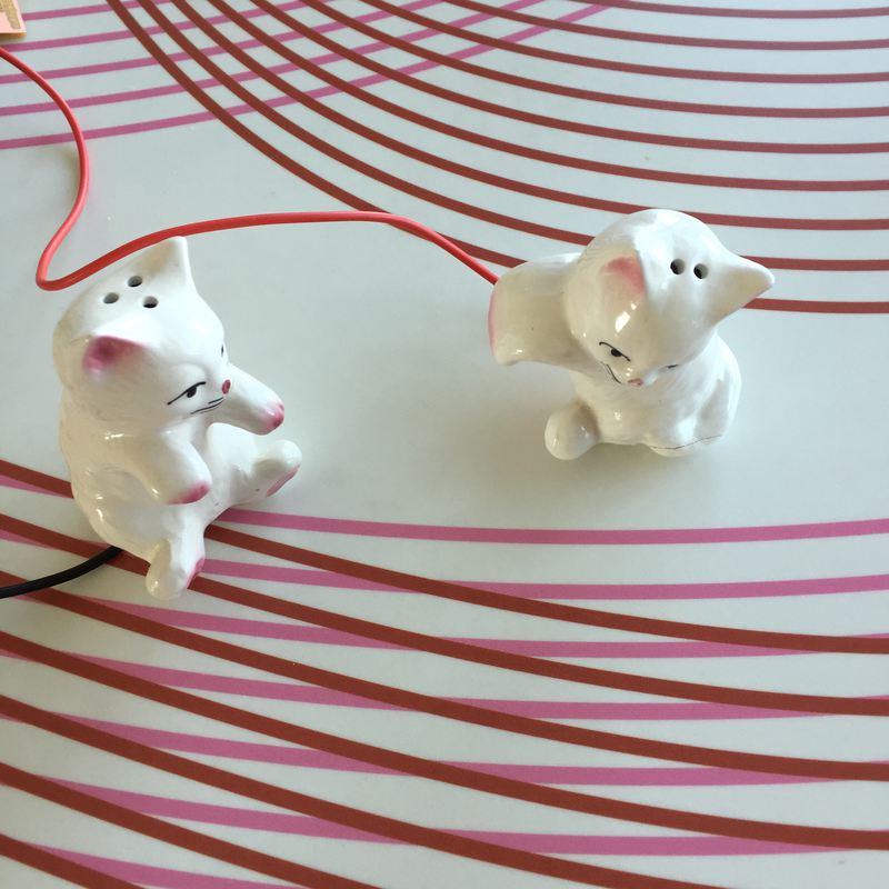
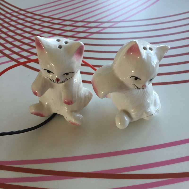
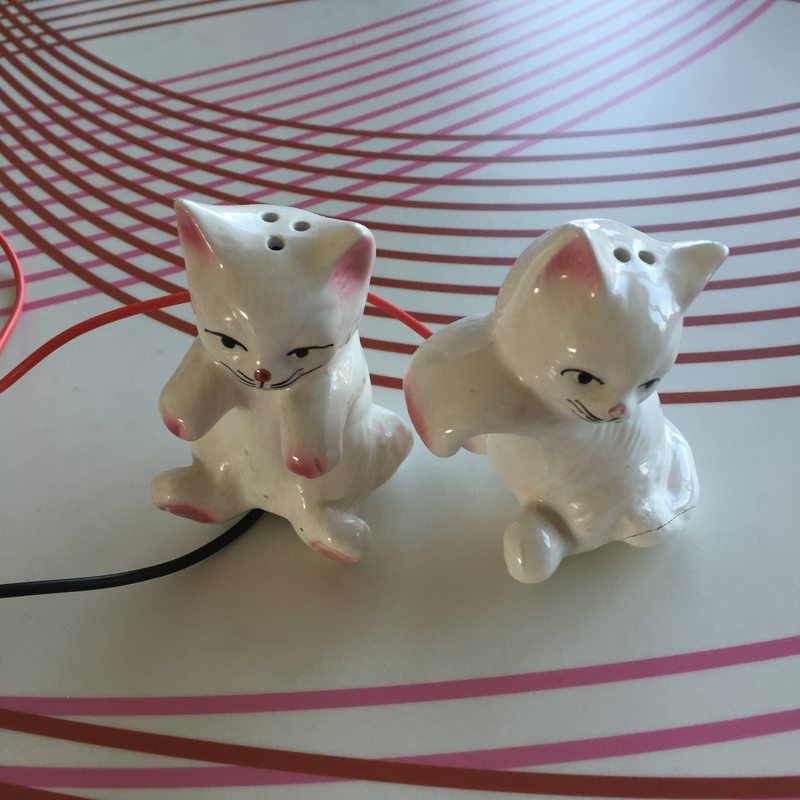
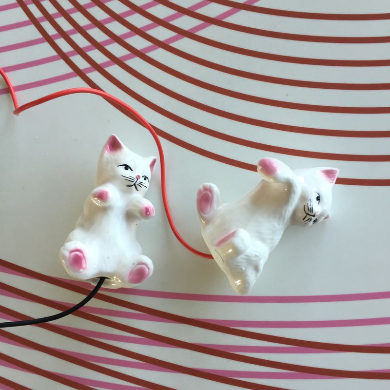
Kitty salt and pepper shakers! I attached the alligator clips to some larger, copper paperclips, and put the paperclips inside the shakers.
And… a short video of the thing giving some numbers.