Week 2: Computer-aided Design
Download this week's code
Little things
I dove into ImageMagick scripting to deal with thumbnails for the site. I wanted square thumbnails to display in the page, and a command to compress the images. This command worked great to generate thumbnails:
$ mogrify -path thumbnails -define jpeg:size=400x400 -thumbnail 200x200^ -gravity center -extent 200x200 *
I'm still experimenting with commands for shrinking the images to below the 100KB limit we're allowed. I was experimenting with this:
$ mogrify -path fusionOut/ -resize 500x *
Software
While watching the weekly lecture, I installed/registered-for a handful of applications that I thought might be relevant. CAD: Fusion 360, FreeCAD, Antimony, Blender, Inkscape, Onshape. HTML editing: Brackets. Image manipulation: ImageMagick. Video editing: Kdenlive. I am already familiar with some of the other applications I plan on using, such as Gimp and Audacity.
We will train in Fusion 360, and if I have a licence then I will use it, but afterwards I will consider open-source alternatives such as FreeCAD. I need to consider the future of my practice, and I don't like the idea of becoming dependent on proprietary packages. Although, this has become a problem in the past, such as when I spent a considerable amount of time on the dataflow environment Pure Data, where the developers had no interest in improving the user interface, while the proprietary Max/MSP was lightyears ahead in usability.
Sketching by hand
I started sketching by hand to plan out how the object might look. Because my primary proposal, performing the machines, is uncertain until I have a better understanding of how the machines can be controlled, I am focussing my attention on my two favourite ideas: the strange birds and the screaming dice.
Even though I am not skilled at drawing, sketching by hand turned out to be a great way to work out practical considerations. Sketching was iterative, each sketch revealed another concern in the design.
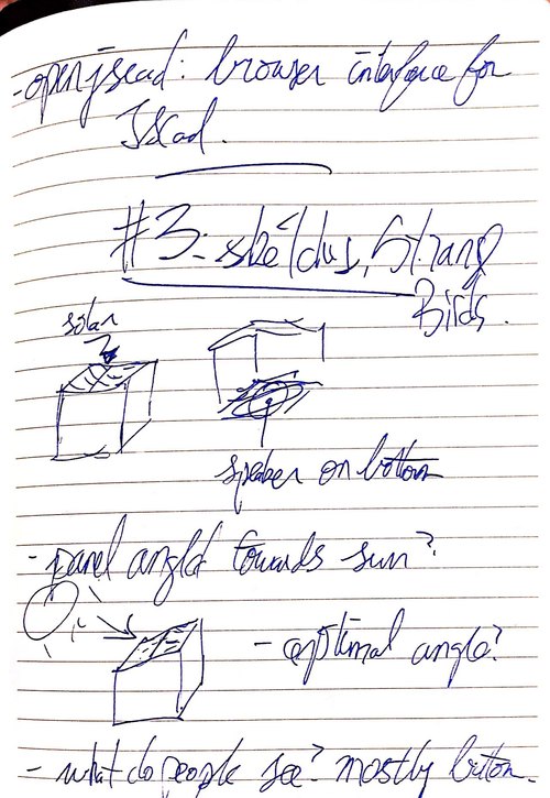
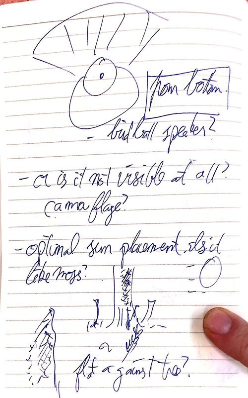
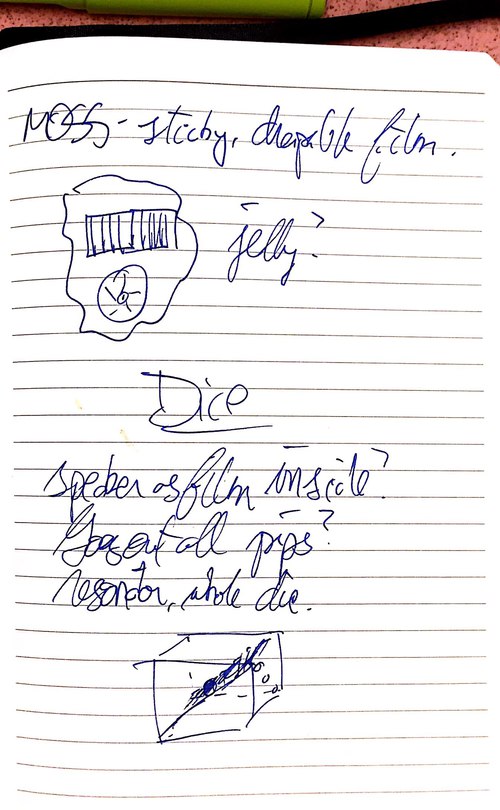
I began with considering basic geometric designs for the Strange Birds, because I think maybe that's the limit of my sketching and drawing ability. I am also unsure about what form they ought to take. The more that I drew, the more I considered non-geomtric options, and specifically options derived from nature. Should the solar-panels be tilted towards the sun to optimise their funtion? What else is directed towards the sun? Moss? Could the thing be like moss, not a box attache to a tree, but a film stuck onto the side of a surface?
And what about the view from underneath? Are they meant to be seen? Should it look like the underside of a bird? Is the speaker the butt? Do the top and bottom need to match? The top can be a cube while the bottom looks like a bird butt.
The dice have a much more straightforward form. But what about the speaker? If it should be heard no matter which side is pointing up, how is the speaker placed internally to do that? Could the speaker be a film mounted diagonally through the centre, so that the pips as speaker grills work? Is the die size and material optimised for resonance for the sound?
Here are some of the sketches I did:
3D Modeling
The Fusion 360 workshop
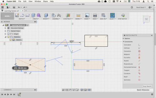
We had a day-long introduction by Mauro in Fusion 360. It was intense. I decided that I would complete the week's assignment in Fusion 360 and then try other modelling software. I'm sure the instructor thinks this is backwards, but there are a few reasons for doing it this way. First, my time is limited, so I need to complete the assignment as quickly as possible so as not to fall behind. Second, it would be a waste of the whole time day to not take advantage of Mauro's in-depth tutorial. Working more on my own with Fusion 360 will give me a better perspective from which to evaluate the other software. I have previous limited experience with Sketchup and TinkerCAD. Fusion 360 seems like a much more powerful piece of software, but that could just be because I had this intensive workshop that demonstrated a lot of what was possible.
Here are some screenshots I made during the workshop:
Trying FreeCAD
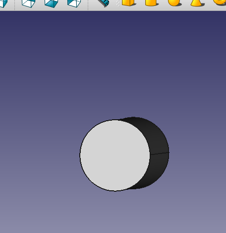
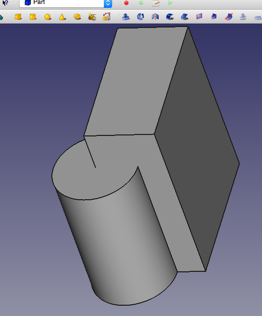
I watched this tutorial to get started. I created a cylinder, and a box shape sharing the same space, and performed a boolean operation to delete the box space from the cylinder. Here are some screenshots to prove that I spent some time making and modifying objects in FreeCAD:
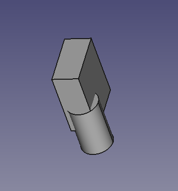
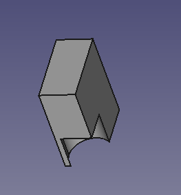
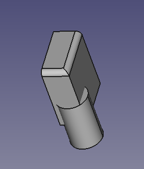
After having spent the time doing the Fusion 360 workshop I think that I'm going to continue using Fusion 360 unless I come across a reason not to. It introduced a way of working that I am now familiar with, and it became clear the FreeCAD saw the world differently. In FreeCAD I spent more time typing in numbers to achieve things that in Fusion360 I would use the mouse for (which is a more natural interaction with designing, though I know that there are advantages to both). I don't have the time right now to learn a different way of viewing the world.
Doing the 3D modelling
Because the form of Strange Birds was starting to become amorphous, I decided to simply model a gaming die, in the interest of the Screaming Dice project. If I follow the moss model for Strange Birds, I may rely more on other techniques (moulding and casting?) than this kind of modelling. Of course, I won't know until I get to that point.
I looked at Wikipedia's article on dice as a reference for how the die is constructed, and this page for reference for die dimensions. Did you know the average die is 16mm? Did you know that in western dice the opposing faces add up to 7? I should have referenced previous Fab Academy students who made dice, but I really wanted to try and figure this out myself from scratch to learn Fusion 360.
Because this will essentially be a container for electronics, I would eventually need to make it as at least two separate parts that can be assembled. But just to learn the tool, my goal is to make a single hollow die where the pips are holes into the centre. The pips are holes because ultimately they will be grills for the speaker inside the die.
I set up a sketch with a single 9-pip die face, and will plan on using this sketch as the template for the other die face. I have specifically used parameters for all the measurements so that I can experiment with die and pip spacing and sizing. The standard die size is 16mm, and everything is relative to that. For example, the pip diameters at the moment are the die's facelength/6, the distance from the die edge is facelength/6, etc. I used constraints to control the placement of the die pips.
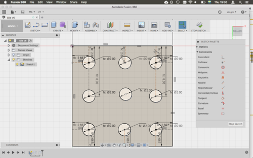
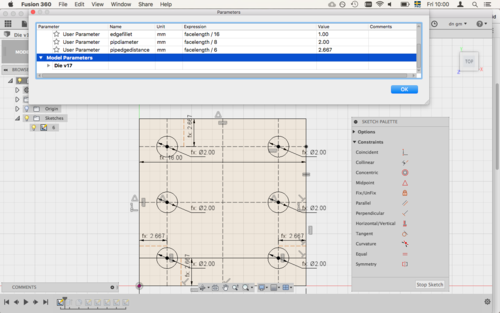
I suspected that I was using the constraints wrong, so I watched a tutorial on how to use constraints. As suspected, the tutorial gave me a different way to think about constraints. I'll rebuild the 9-pip face using a grid of guide lines determined by some constraints, like mid-point and coincident.
Set up a 3x3 grid for a die face. Extruded that into a cube the size of the dice length parameter. Copied the sketch into sketches on the planes of the die faces, and moved them to form the die. Deleted pips to make numbers on all sides. Changed dimensions, some sides didn't change! Must have something to do with how I set up the constraints. Start again? I decided to see what the problem was before I started from scratch. I couldn't fix the line in question, but I was able to delete it an recreate it with more carefully thought-out constraints.
I went back and re-edited the original sketch template, changing the guidelines and their constraints, and then did some resizing of the sketch parameters, watching to see what happened, and the results looked fine. No more weird guideline tilting.
But I tried resizing the die, and everything went strange. Some faces didn't resize. Why?! And, as I should have expected, the faces didn't move, because I had pasted those sketches using numbers rather than parameters. But I suspect that I don't know how to do what I'm trying to do. I want to be able to change the size of the die, and everything changes in proportion, and that would mean that, the way that I'm currently doing it, the placement of the sketches would have to change according to the parameter of the die. Is that even possible?
I tried pasting and moving the sketch according to the facelength parameter for the length of a die face, and the new face wouldn't change size when I changed the parameter. I watched a tutorial on parameters. Maybe I should have at least started with a centre rectangle? I was also reminded how to add the use parameters to the toolbar.
Because time is limited, and parametric design isn't needed until next week, I will just make a static die, with some parameters, to satisfy the assignment criteria, and I will try to fix my parametric problems next week. ... I wrote that, but I still can't shake the challenge of working out the parameters.
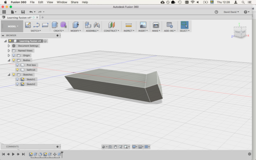
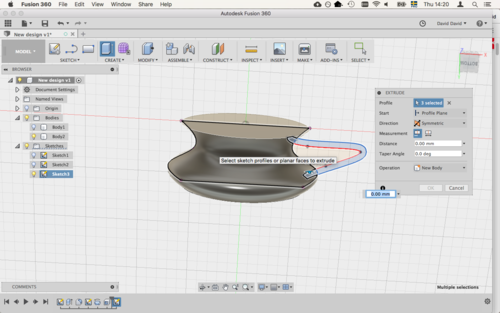
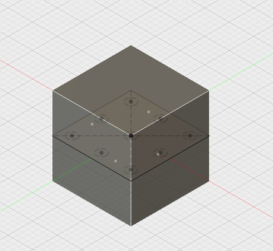
Extruding from the centre made pasting the sketches much easier! Spacing was perfect. Pip spacing now uses fewer guidelines, because I'm using smarter constraints. Here is the extruding:
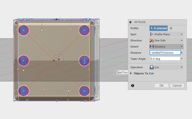
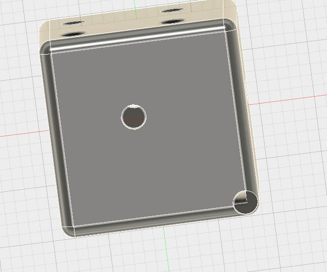
Sketch pasted to all cube faces, removed the pips so that numbers match. Next step, shell command to make the cube hollow, then remove the pip spaces. Extrude? Or hole? I tried to extrude all the holes at once, but I couldn't seem to extrude on other planes. What other options might I have to sink all the holes at the same time? So I did each face separately. Afterwards I tried to change the parameters to see what happened, but it still screwed up. I need some external help for this. Here is a shot of the pips being extruded inwards to make the holes, and of the die resized using a parameter, generating weird spacing.
Rendering and exporting
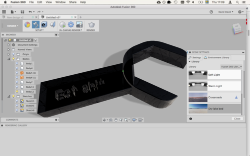
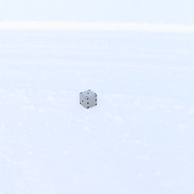
By going into render mode and experimenting with different materials and environments, I rendered the die on a snowy background, because, why not.
I have exported my Fusion 360 design of the die, and the file is available here.
Using the Animation mode of Fusion 360, I did a simple camera spin and exported it to a video:
fullDie from David McCallum on Vimeo.
2D Modelling
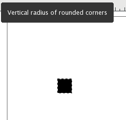
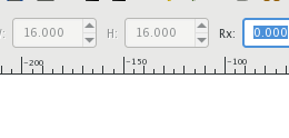
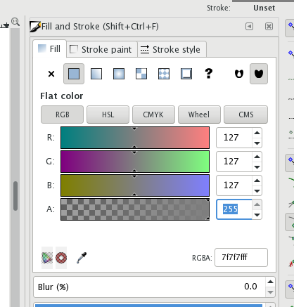
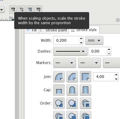
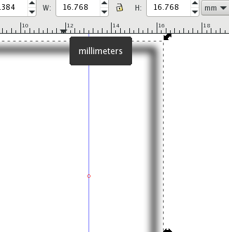
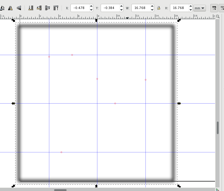
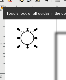
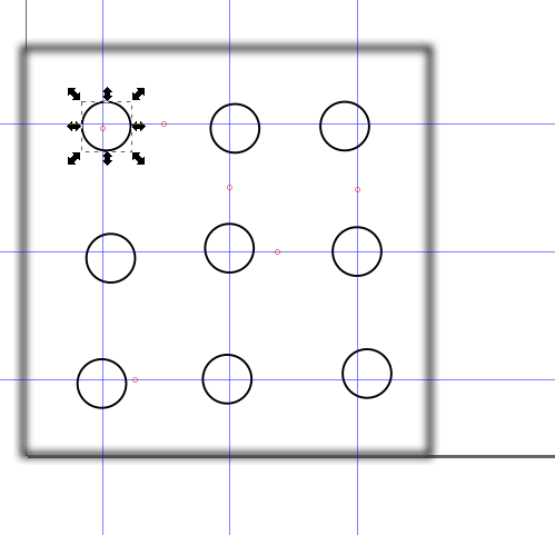
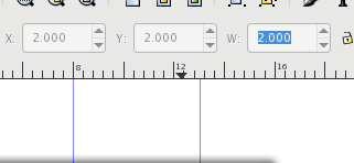
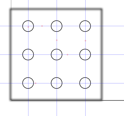
I have limited experience doing 2D vector modelling with CorelDRAW, LibreOffice, and Adobe Illustrator. I decided to try the open-source option, Inkscape. I watched this tutorial on Inkscape basics. I also looked at this tutorial about parametric design in Inkscape. I decided for Inkscape to start in a similar way to what I did in Fusion 360. I created a blank die face with 9 pips that could be deleted to form all of the faces of a die. I did not do parametric design, but I did use the clone tool for the pip circles so that they could all be changed together. I created some guidelines, but have not yet learned how to snap objects to the guidelines.
The file for this design is available here.
I learned a little of how Inkscape thinks about objects and their properties, but the environment still feels a little clumsy to me. Obviously I need to spend more time working with it, especially since I imagine it will be used for all of the cutting machines. Here are some screenshots of making the die face: