Week 7: Computer-controller Machining
Download this week's code
Assignment requirements
The task: Make something big.
Checklist:
- Explained how you made your files for machining (2D or 3D)
- Shown how you made something BIG (setting up the machine, using fixings, testing joints, adjusting feeds and speeds, depth of cut etc)
- Described problems and how you fixed them
- Included your design files and ‘hero shot’ photos of final object
General learning outcomes: Document the process of design and production to demonstrate correct workflows and identify areas for improvement if needed.
A workflow for this machine for this project
Thinking and drawing
Think about what you want to make.
A summary of the change in the design: started as a rocking horse, then a Catbus rocking horse from My Neighbour Totoro, to a boring step stool for my sons, to a step stool using the shape of my youngest son's head.
I looked through the Fab Academy archive for inspiration. Something for my kids? I asked my wife what she wanted me to make this week. She said a headboard for our bed. Later she suggested a rocking horse for our almost-walking baby. I started googling for images of rocking horses, and images of CNC rocking horses, and fab academy rocking horses. It's a favourite! It also looks like a relatively straightforward design to implement. Then I thought, what else could it be? What other kind of animal? After considering strange things, I remember our older son's favourite film, My Neighbour Totoro. Could I make a Totoro rocking horse? After googling images of Totoro, it was difficult to find a form of him that would suit a rocking horse. But the Catbus… That's a possibility. After sketching out the catbus with a rocker, I realised that it needed some kind of handle (this is normally the horse's head). I decided that I could be liberal with the forms. Totoro's size is about right to place him sitting on top of the Catbus to act as handle. So, the kid rides the bus, holding on to Totoro.
In the end, I had such huge problems with sketching the catbus, and wouldn't have enough time to face the unavoidable other problems I was going to face, I gave in and decided to do a boring step stool for my children, based off of dimensions of an Ikea step stool that we have at home. I made the stool in Fusion 360 on the train home, and the next morning, on the train to Amsterdam, I couldn't just let the project be boring, so I redesigned the legs of the stool to use the shape of my son's head from the press-and-fit kit from week 3.
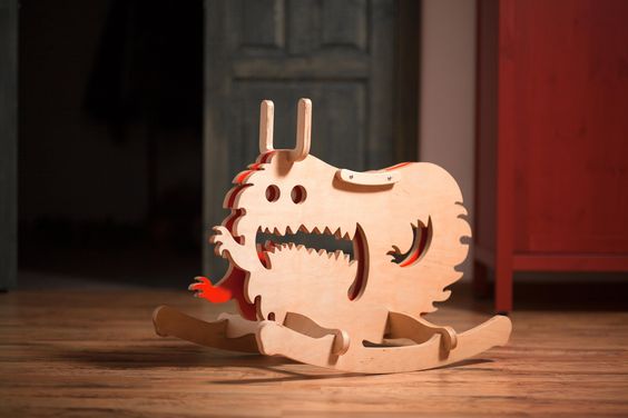
Inspiration, a possible rocking horse inspiration from Constantin Bolimon, and characters from My Neighbour Totoro.


Sketch it out. Does it look terrible? Try it differently.
I sketched out the catbus. I then sketched out the stool, trying to have some curvy shape.
Sketch it out in real space. Like in cardboard. Does it look terrible? Try it differently. The catbus was done in cardboard. The stool I didn't.
Think about how it will fit together.
Joints? Slots and tabs? How big will they be, and where? Do you need metal fasteners? Can you avoid them?
The catbus cardboard model was based on other rocking horses I saw online, but I had to consider how to modify the catbus shape, and attach a Totoro as a handle.
The stool was made with a horizontal step, and Emma suggested that I put in a vertical support underneath for side-to-side stability.
Consider your joints.
Model them in CAD. Mill a test to see if your slot clearance works. Clean up the test before assembling the pieces (your test should be as close to your final reality as possible!).
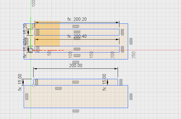
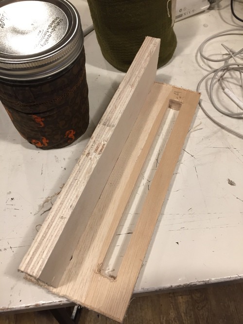
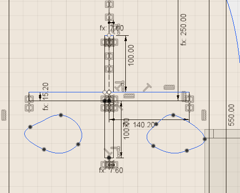
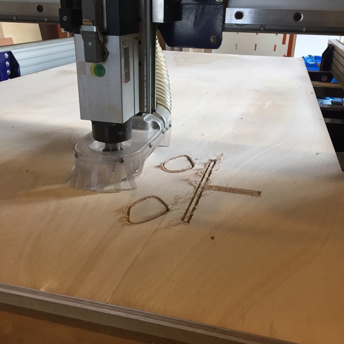
I made a simple test with two slots of different clearances (.2 and .4mm), and a single piece with a tab to test how it works with the different clearances. At first I forgot to sand off the remains of the tabs, and it was very tight. After sanding them off, .2mm worked just fine.
The test slot pieces.
Model your pieces in CAD.
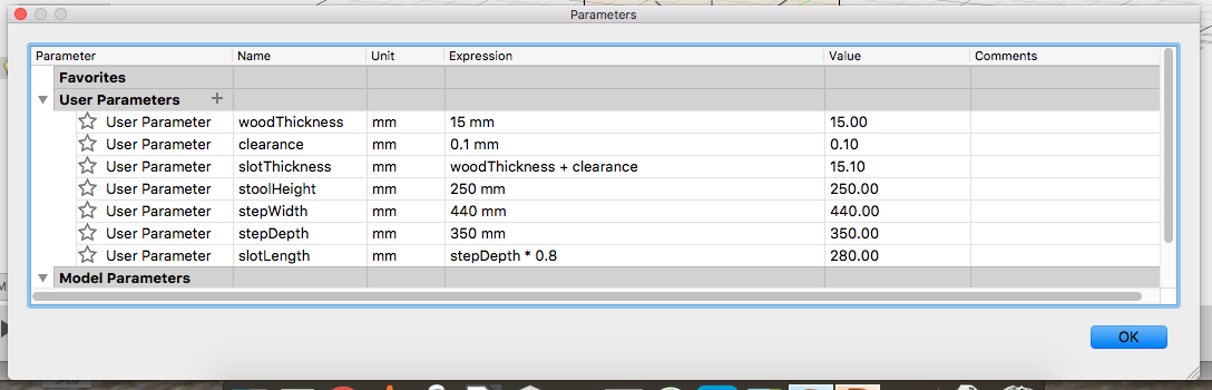
In Fusion 360, make sure that the different pieces are created as Components. Create user parameters for things like wood thickness, clearance, and any other dimensions that may change or that are the basis for the calculation of other dimensions.
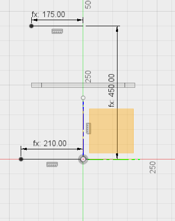
I originally modelled the boring stool. The step height and dimensions were based off of the Ikea stool. The side legs were made using splines. I experimented with making it curvy.
I extruded the shapes into pieces, and "assembled" them using "align". I found some errors in measurement, I went back to the sketches and adjusted the measurements.
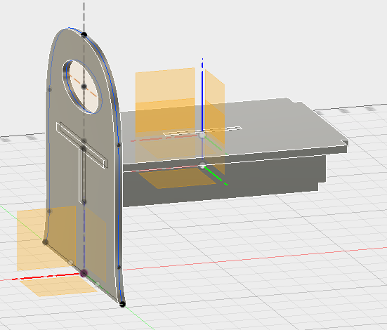
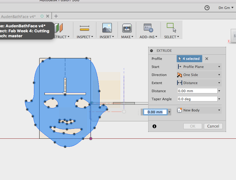
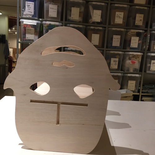
Then I decided to do the baby head. I enlarged an image of my son to about the right dimensions for the side feet, traced it out and added the slots as they were in the boring stool. The existing step and support pieces could be re-used.
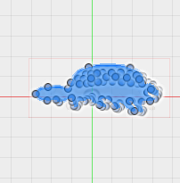
Here are some images of trying to model the catbus in splines, which became a squidgy blob, using user parameters for a parametric design, and some shots of designing the boring step stool and then the baby-head version using the parameters.
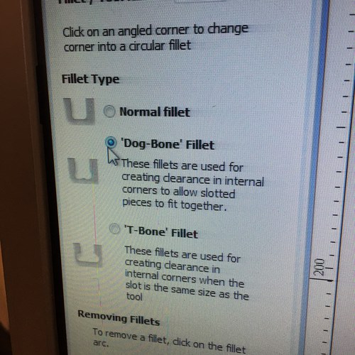
Dogbones go where? Either in your CAD files, or later, in the milling software. I did them in the milling software, but in the future I would rather do them in Fusion 360. My intention is to do as much of the process in Fusion 360, including planning toolpaths.
Mill it
Prepare your files for milling
I should learn how to do all the toolpaths in Fusion, but I used the process that we were taught, creating toolpaths in PartWorks, an ancient programme that doesn't like people.
In Fusion 360, you can export the sketch that you used to create your pieces as a DXF by right-clicking on the sketch and selecting "Export to DXF". I think there must be a way to do this from the 3D body itself. I don't know yet, but I would like to.
Clean up the vectors. Open up the DXF in Illustrator. Make sure that Illustrator's default units are set to millimetres, or else Illustrator does weird scaling. Delete any construction lines from Fusion. Shorten other lines to where they ought to be. If a line segment needs to be split, you can add anchor points by selecting the tool of the Pen tip with the +, and selecting and right-clicking on the line to add an anchor point. You can then use the scissors tool to split at that point, and then shorten the resulting lines as you did before. You can probably also add two anchor points and delete the segment between them; I haven't investigated that. Make sure all vectors are closed. You can do this in illustrator with the command Object - Path - Join with your vector selected.
Use these Illustrator tools to create anchor points in long vectors, and to cut them for resizing!


Save a copy in an older Illustrator format. I did CS2, under Bas' advice. Bas was hepling us with the Shopbot this week. You can also try your luck with PDF or DXF again. Copy it to a USB stick and take that to the ShopBot computer.
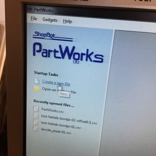
Copy the files to the local harddrive. (Maybe this is needed, maybe it's Fab Lab superstition.) Open the files in ParkWorks. Click Create New File. Import your shapes by Import Vectors (CTRL-I). Everything should show up on the canvas.
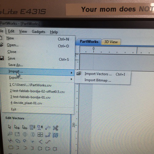
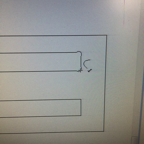
If you haven't added dog bones in the original file, now is the time to do it. Click the Fillet tool in the toolbar. Choose your type of fillet, and then click each corner to create a fillet.
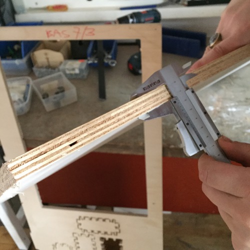
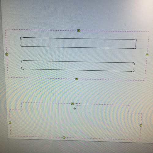
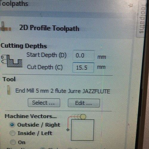
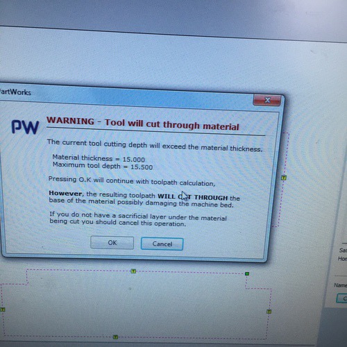
Measure your material with a micrometer to confirm that it is the thickness you would like. You may have to alter the cut depth if it is a different thickness. Now create toolpaths. Select the vectors that will share a toolpath, then hover the mouse over Toolpaths in the top right of the screen, out will pop a tray. For my purposes, I chose a Profile path. Set the Start Depth and Cut Depth. I chose a cut depth of .5mm lower than the bottom of my material, on recommendation from Bas. Our group assignment showed that this mostly cut through the material, and occasionally did not cut entirely through, but produced a very thin surface that could be easily broken by hand.
Set up your tool here. Here you can set various parameters that will each affect your cutting. Everything is a trade off between speed and other unsavoury outcomes (dulling the tool, breaking the tool, fire).They are:
- Diameter: size of the tool?
- Pass depth: the active cutting length of the tool
- Stepover: how much passes will overlap with each other (Usually no more than 50%).
- Spindle speed: spinning speed
- Feed rate: the tool's lateral speed
- Plunge rate: the speed of descent of the tool into the material
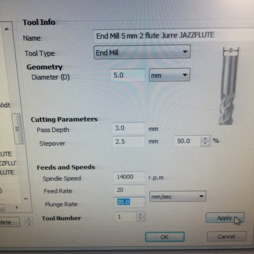
The values here were chosen in consultation with Bas, and based on our group assignment testing. During the cutting, I was pleased with the sound the machine was making and the speed, and did not see fit to adjust them. But if the machine sounded like it was working too hard then the speed could be increased or the feed decreased, for example.
This can all be saved as its own tool preset to be used again.
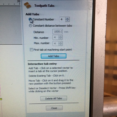
After configuring the tool, configure the toolpath. Set whether it will cut inside or outside the line (depending on the role of the line in your sketch), climb or conventional. Then create tabs to keep your pieces in place. I made square tabs, the size of half of the wood width. Click Edit tabs to create the tabs, and either create them automatically or click them into the toolpath yourself.
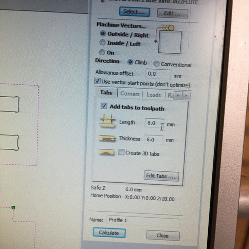
Finish by clicking "Calculate". You will receive a warning that this toolpath will cut through the material. It's fine.
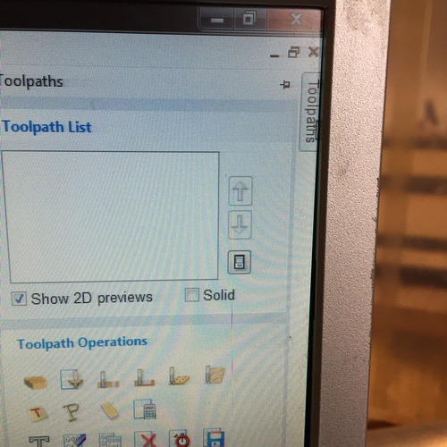
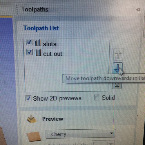
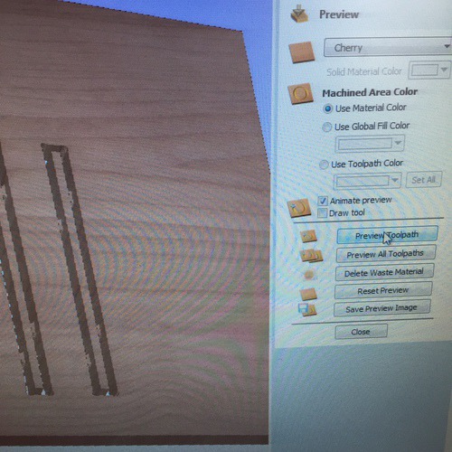
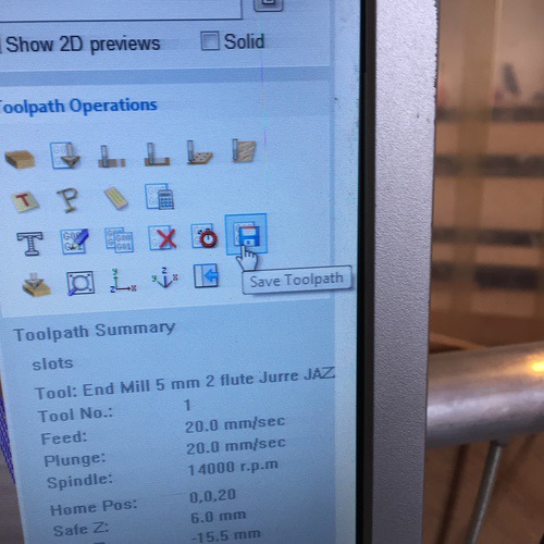
Repeat this process for other toolpaths. Then select the order that the cutting is performed by shifting them around with the arrow buttons. Select all toolpaths and click Preview All Toolpaths to get a visualisation of the toolpaths. Then click all toolpaths and then the button "Save Toolpath." This will create a cutting file to be used by the Shoptbot software.
Milling
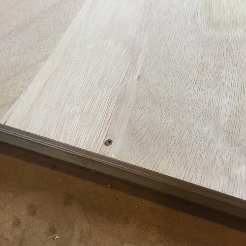
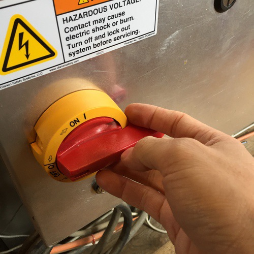
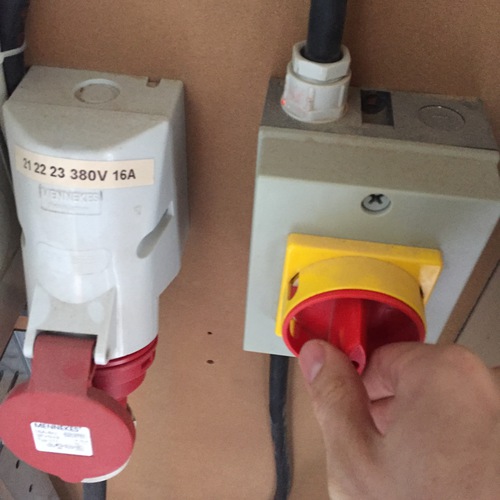
Attach your material to the sacrificial layer with a few screws along the edge. Make sure it is flat! Turn on the machine with the big red switch. Start the Shopbot software.
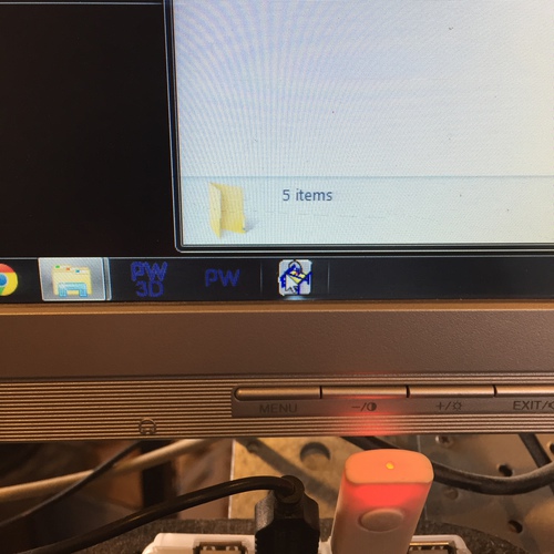
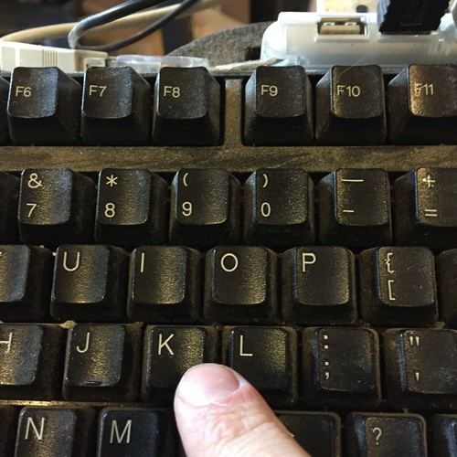
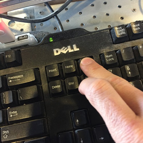
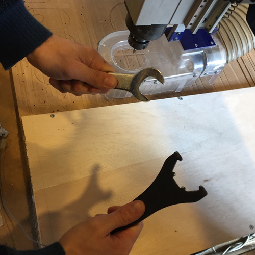
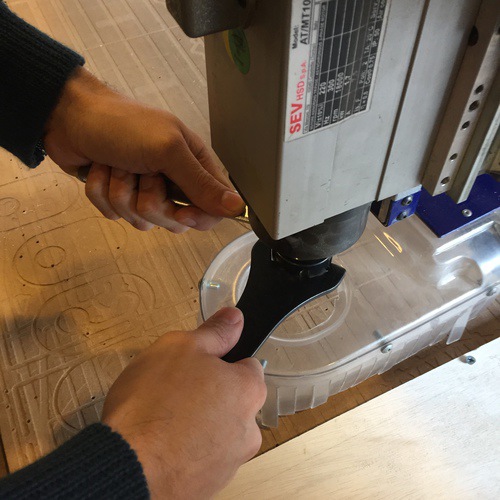
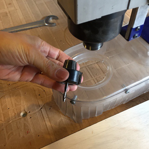
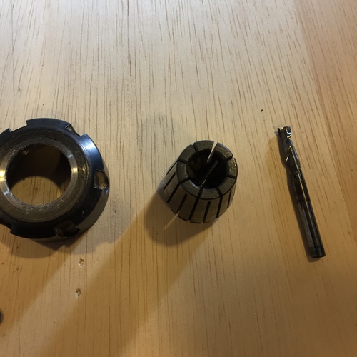
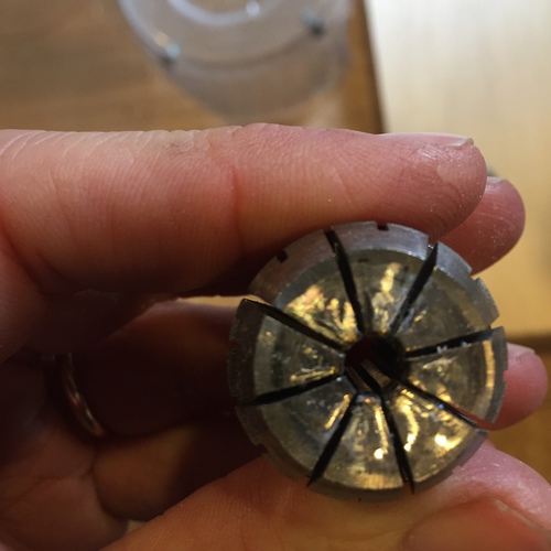
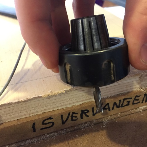
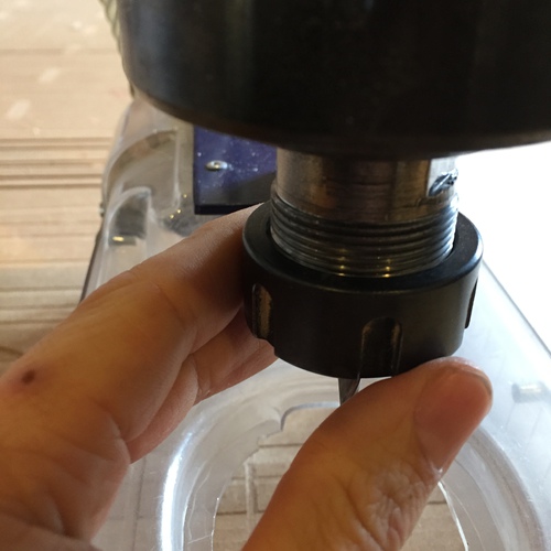
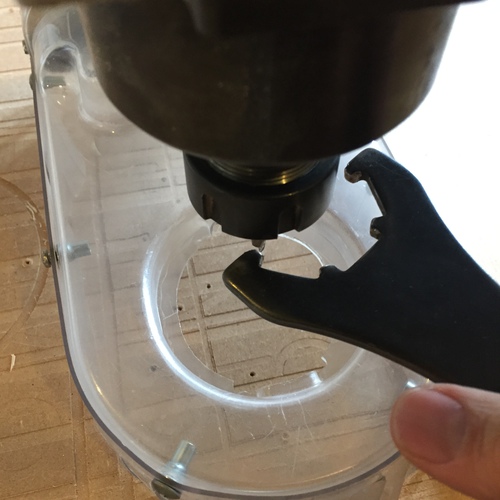
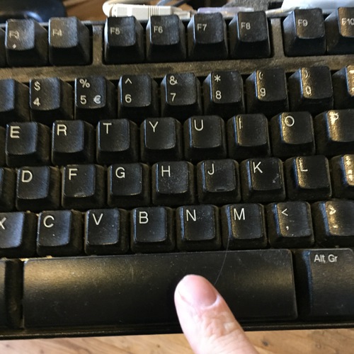
Change the endmill. Press K to open a panel to move the machine head. Use the arrow keys to move the X and Y, user PgUp and PgDn to move the Z. Position the head where it will be easy to add the endmill. Release the wingnut at the back of the assembly to lower the vacuum skirt. Use the two wrenches to loosen the collet. Remove the collet, find a collet that matches your endmill size. Check the endmill depth coming out of the collet. Screw it in loosely, then tighten with the two wrenches.
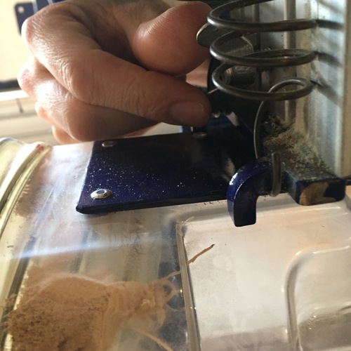
Set the origin. Again using the arrow keys and PgUp and PgDn, position the endmill where you would like your origin. Click Zero in the menu and then Zero 2 Axes. Move the endmill a little further into the material, then place the z-calibration plate underneath the endmill. Touch it lightly to the endmill to see that a connection is made (a little light turns on on the screen). Then click the z-calibration icon. Hold the metal plate down with both hands while the bit is lowered until it touches the plate. Then move the bit up again manually (this is supposed to be automatic but isn't working).
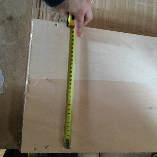
Measure the material from the origin to make sure you have enough room to cut!
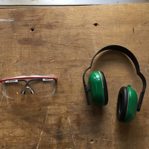
Put on your safety equipment!
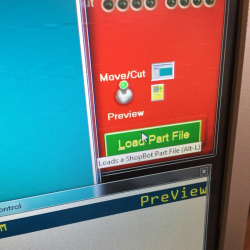
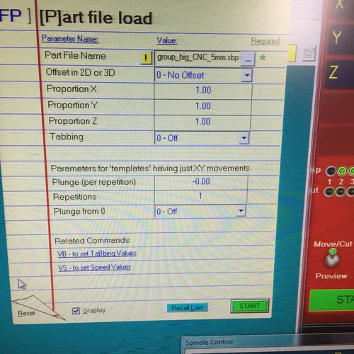
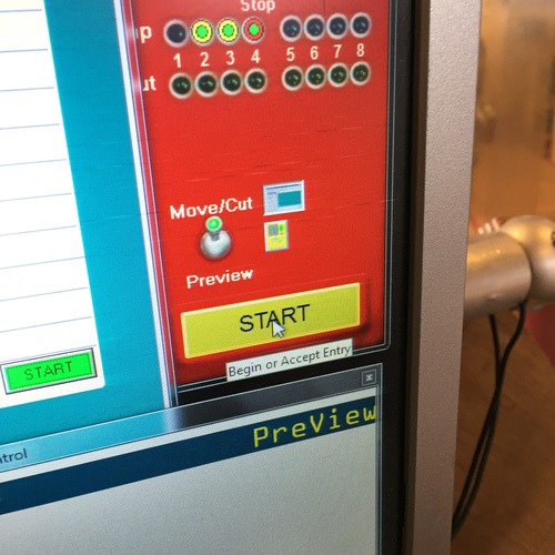
Turn on the extraction system with the switch at the back wall and the switch on the front of the Shopbot. Load your toolpath file. Put the key into the machine and turn it gently. On the computer click "Start" and be ready to cancel the job with the spacebar if something goes wrong!
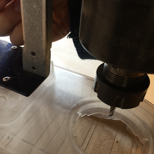
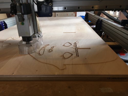
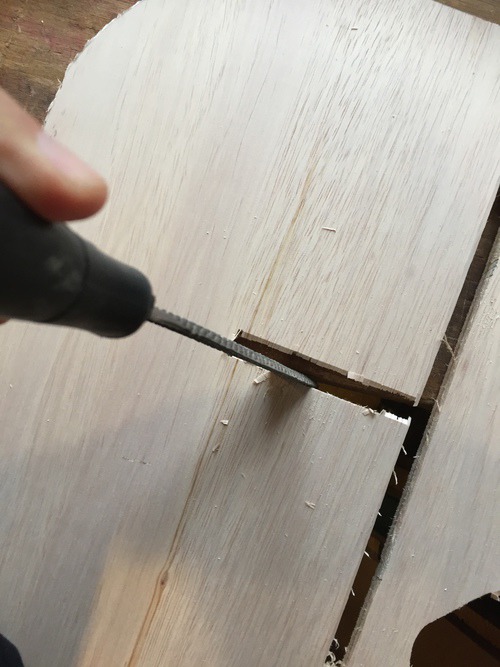
When the job is done, gently remove the key to stop the bit spinning. MAKE SURE IT HAS STOPPED SPINNING. Press K and move the bit out of the way. Vacuum the traces in your material. Unscrew your material, remove it. Here it's cutting!
Cleaning up
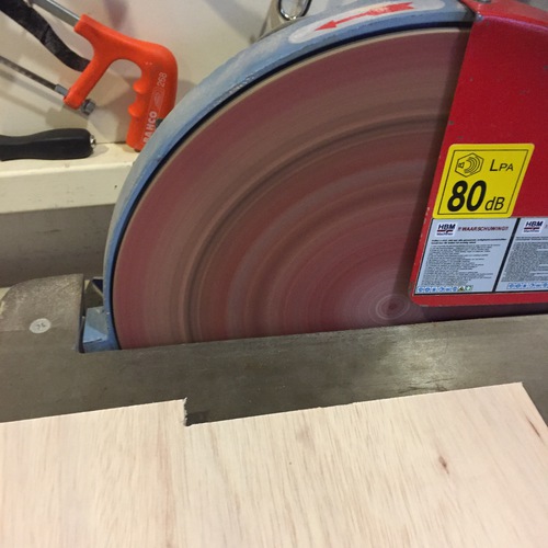
Use various kinds of saws to cut the tabs. Use files and sandpaper and sanding machines to clean up the edges.
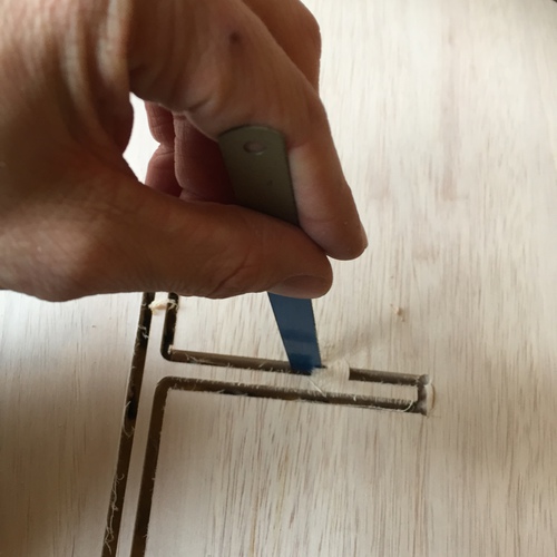
Note! Work with the woodgrain when using the file, otherwise the material gets ugly.
Note! Do your joints not fit? Use a file to make the slots bigger. Use a mallet to gently tap things together. This is a compromise between the efficiency of your initial slot testing and the actual final results of the material. If you do enough testing, this shouldn't be a problem.
In the end
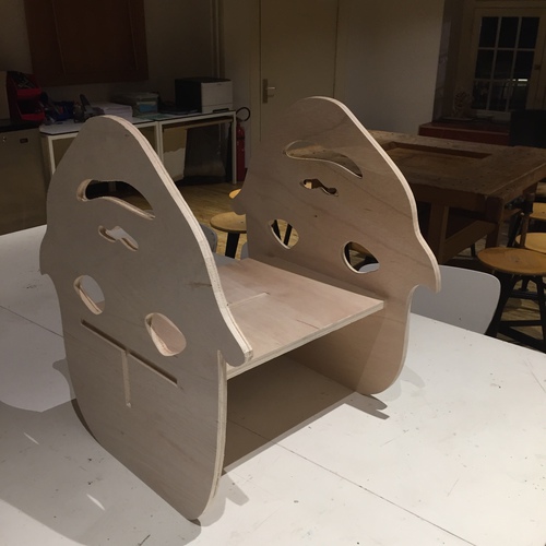
Here is the final piece, not fully tapped together:
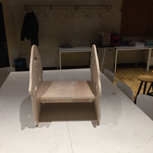
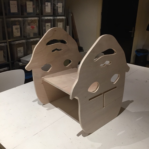
Ultimately, this thing is not safe to be a step stool. The base is not wider than the step, making it prone to tipping, and the rounded lower edges encourage this rocking. More time spent with things like cardboard models would have shown this. But… did I accidentally make some kind of rocking toy after all?