Week 8: Embedded programming
Download this week's code
See our group assignment here.
Assignment requirements
The first checklist
- Read a microcontroller data sheet.
- Program your board to do something, with as many different programming languages and programming environments as possible.
- Optionally, experiment with other architectures
Learning outcomes: the second checklist
- Identify relevant information in a microcontroller data sheet.
- Implement programming protocols.
Have you: the third checklist
- Documented what you learned from reading a microcontroller datasheet.
- What questions do you have? What would you like to learn more about?
- Programmed your board
- Described the programming process/es you used
- Included your code
Reading a microcontroller datasheet
I have done a fair bit of Arduino programming, even Arduino on an ATtiny45, but nothing more serious than that. I've only dipped into datasheets in little bits to get small bits of information, so reading one thoroughly is a different task entirely.
Two datasheets:Things I learned from the datasheet
- It's full of terms I don't understand.
- It says maximum write/erase cycles. There's a limit! I suspected but never really knew.
- There's an on-board temperature sensor!
- Why does it reference pages that aren't in the document? Oh… There are two different datasheets, a short one and a long one.
- It mentions alternate port functions! What could those alternate functions be? But when I checked it out, I didn't really understand what it was saying.
- What's a register?
- The diagram (p 4) of the microcontroller makes little sense to me except to see that the pns are divided into 2 ports, whatever that means.
- 3.3 Capacitive touch sensing! Is it easy?
- 5 - Is it listing the assembler commands?
- 5.3.1. sometimes powering on an off on heavily filtered power supplies can corrupt the eeprom because the device may work at a lower voltage than specified. That is worth knowing in some applications.
- 6.1.4 Something about ADC clock can run independently of the CPU clock to reduce noise? That's interesting. When would that be useful?
- 10. All ports are I/O ports, and independent of each other! That sounds powerful, if I understand it.
- In the pin i/o section it describes what you can do with the pins, but I realise that I would rather see code examples than text descriptions of how to do things.
- 14. It has built-in serial.
- How do the internal comparators work? What can we use them for?
- 17. Can the internal debugging be of use to us?
- 20.3 interesting to see a link between Vcc and possible chip speed. Useful to know if I want long battery life or low power comsumption.
Other research
I poked around Fab Archive. Looked at Jacopo de Matteo, he seemed a little more advanced than me but point out similar things, like never really understanding the avrdude syntax. So I decided to be like him and poke around the man files and shell flags. By the way, to get this code to display correctly I had to have all the HTML-relevant characters escaped. I used this page. So:
$ avrdude
Usage: avrdude [options]
Options:
  -p                 Required. Specify AVR device.
  -b               Override RS-232 baud rate.
  -B               Specify JTAG/STK500v2 bit clock period (us).
  -C            Specify location of configuration file.
  -c             Specify programmer type.
  -D                         Disable auto erase for flash memory
  -i                  ISP Clock Delay [in microseconds]
  -P                   Specify connection port.
  -F                         Override invalid signature check.
  -e                         Perform a chip erase.
  -O                         Perform RC oscillator calibration (see AVR053).
  -U :r|w|v:[:format]
                             Memory operation specification.
                             Multiple -U options are allowed, each request
                             is performed in the order specified.
  -n                         Do not write anything to the device.
  -V                         Do not verify.
  -u                         Disable safemode, default when running from a script.
  -s                         Silent safemode operation, will not ask you if
                             fuses should be changed back.
  -t                         Enter terminal mode.
  -E [,] List programmer exit specifications.
  -x         Pass  to programmer.
  -y                         Count # erase cycles in EEPROM.
  -Y                 Initialize erase cycle # in EEPROM.
  -v                         Verbose output. -v -v for more.
  -q                         Quell progress output. -q -q for less.
  -l logfile                 Use logfile rather than stderr for diagnostics.
  -?                         Display this usage.

avrdude version 6.3, URL:
Only the first few flags seem to matter to me. The others maybe if I run into problems.
I read the man page for avrdude. I learned that there is a terminal mode which allows basic communication with the chip, and allows us to directly write memory. It mentions debugWire, which I remember reading in the datasheet is an on-chip debugger, but I still don't know how to use it.
I would like to see if I can wriet the code directly in C. So I looked at Neil's original hello echo code. He sets the serial direction to DDRA. What is that? Check the datasheet. 10.3.3 Port A Data Direction register with a bunch of bits listed.. OK, so what direction is it?
Programming the board
I made sure I downloaded the latest version of the Arduino IDE, because it has been a while since I've done that.
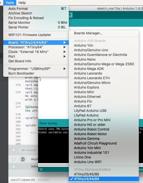
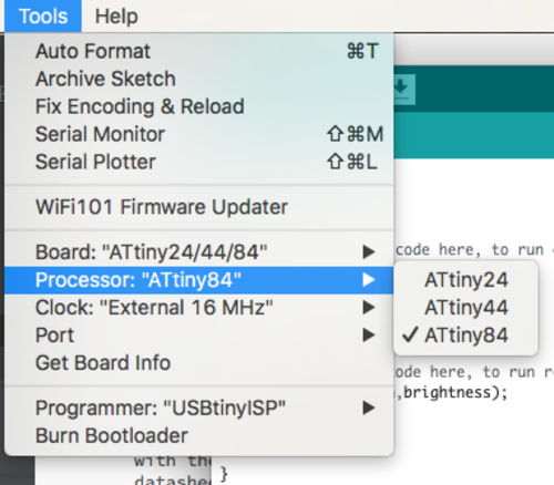
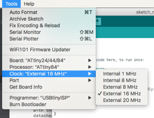
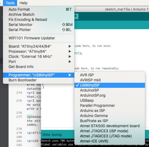
I added Dave Mellis' Arduino cores, according to Joris' instructions. Then in the board manager, select the attiny and install. Set the boardtype attiny24/44/84, then processor ATtiny84. Then the clock to external 16MHz. Then programmer to USBtinyISP. Compile and upload using the buttons in the Arduino IDE.
ATtiny84 arduino pinout is available here, which is a useful reference.
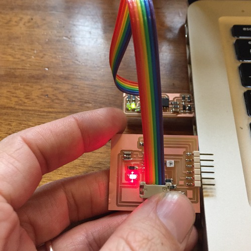
My LED was soldered in wrong orientation! Used the heat gun to remove and resolder.

I did not set an internal pullup resistor for the button because I put one into the circuit when I designed it. I had forgotten about internal pullups.
I had a problem with serial. I did not receive anything. Was it the FTDI cable? I plugged Henk's board (with a softserial sketch loaded) into my FTDI cable, I received data from his board.
Was it my board? I plugged my board into Henk's FTDI cable and his computer, received nothing. I checked my board against Henk's and the schematic and everything was as it should be.
Was it the solder connections? I used the continuity check on the chip pins and FTDI connector. All connections were good. There were no shorts.
So what was it? Emma checked herself, and suggest I reburn the bootloader. … It worked. When in doubt, burn it down and start again.
I have used plenty of Arduino before. But to satisfy the assignment I have provided two basic sketches for my hello echo board. One will fade the LED up and down, incrementing a decrementing a brightness variable depending on whether or not the button is pressed. The other uses the phototransistor to control the brightness of the LED. The darker it is, the brighter the LED. They are presented at the top of the page.
For the button code, I established variables for the pins (they could be constants), and for the brightness. I read the button state using digitalRead(), and use some if… else statements that control how the brightness variable is modified (is it increased or decreased?). Afterwards the brightness is constrained by using the modulo operator (%) so that it loops back to 0 or 255 when it goes too low or high. The LED is then pulsed using analogWrite(). Here's the code:
// David McCallum, 2018


int ledPin = 7;
int brightness = 0;
int buttonPin = 3;


void setup() {


  pinMode(ledPin,OUTPUT);
  pinMode(buttonPin,INPUT);
}

void loop() {
  int buttonState = digitalRead(buttonPin);


  if (buttonState == LOW) { // pressed
    brightness+=10;
    }
  else {    // not pressed
    brightness-=6;
   }


    brightness = brightness%255;
   // brightness += 15;


    analogWrite(ledPin,brightness);
    delay(1);


}
The phototransistor code is set up very similarly to the button example. The phototransistor value is read using analogRead(), and this is mapped to PWM values using the map() function. I experimented with different values until I reach a behaviour I liked, and constrained the values using the constrain() function so I wouldn't get any weird behaviour from mapping that went outside of 0-255. Here's the code:
// David McCallum, 2018

#define photoPin 2
#define buttonPin 3
#define ledPin 7


int photoValue = 0;
int buttonValue = 0;


void setup() {

  pinMode(photoPin, INPUT);

}

void loop() {

  photoValue = analogRead(photoPin);

  int temp = constrain(map(photoValue, 0, 400,255, 0), 0, 255);
  analogWrite(ledPin, temp);

}
Here's a video of the phototransistor in action:
Experiments in C
I looked at Neil's code in the Input devices week to see how to do it in C. I am really having trouble understanding it, because few of them are straightforward. So I googled for beginner AVR tutorials. I may look at this one from Hackaday later, which seems very extensive.
Blinking an LED in C
I started here. This is the code from that page:
//
// A simple program for the ATtiny84 that blinks an LED.
//
// electronut.in
//

#include <avr/io.h>
#include <util/delay.h>

#define F_CPU 8000000

int main (void)
{
  // set PB1 to be output - connect your LED to pin 3
  DDRB = (1 << PB1);

  // loop
  while (1) {

    // set PB1 high
    PORTB = (1 << PB1);

    _delay_ms(200);

    // set PB1 low
    PORTB &= ~(1 << PB1);

    _delay_ms(200);
  }

  return 1;
}
I changed the pin designation to PA7, which I think is the pin that has the LED on it. I also commented out the line for the CPU speed, because we're using an external resonator. I think this should work. I got an error when triyng to compile.
$ make
make: *** No rule to make target `main.o', needed by `main.elf'.  Stop.
I googled a bit, and realised that the code should have been called main.c. I renamed the file. It compiled and uploaded correctly. … But the light didn't blink. I took a look again at the code and suspected that everything with a B in it should be an A, because the LED pin in on port A. I recompiled, and it worked! The code is now:
//
// A simple program for the ATtiny84 that blinks an LED.
//
// electronut.in
//

#include <avr/io.h>
#include <util/delay.h>

//#define F_CPU 8000000

int main (void)
{
  // set PA7 to be output - connect your LED to pin 3
  DDRA = (1 << PA7);

  // loop
  while (1) {

    // set PA7 high
    PORTA = (1 << PA7);

    _delay_ms(200);

    // set PA7 low
    PORTA &= ~(1 << PA7);

    _delay_ms(200);
  }

  return 1;
}
Pulsing an LED in C
Then I googled for attiny PWM in C, and I found this site. I modified the code, commented out some stuff that was giving me errors when I tried to compile it, and got a pulsing LED! I still don't really understand how yet. I know that the original code was for a three-colour LED, and so there are a whole bunch of commands here that are not relevant to pulsing a single LED. The code is thoroughly documented, though I still don't understand much of what it's talking about, so I need to read through it more and consult the datasheet. Still, at least it pulses!
/*
all my ATtiny85 chips have their 8MHz fuse set
by default they run at 1MHz, so adjust accordingly
this constant is used by delay.h, so make sure it stays above the include
*/
//#define F_CPU 8000000

/*
io.h provides lots of handy constants
delay.h provides _delay_ms and _delay_us functions
*/
#include <avr/io.h>
#include <util/delay.h>

/*
program entry-point
*/
void main()
{
    /*
    Starting values for red, green and blue
    */
    uint8_t r=0, g=85, b=170;

    /*
    Port B Data Direction Register (controls the mode of all pins within port B)
    DDRB is 8 bits: [unused:unused:DDB5:DDB4:DDB3:DDB2:DDB1:DDB0]
    1<<DDB4: sets bit DDB4 (data-direction, port B, pin 4), which puts PB4 (port B, pin 4) in output mode
    1<<DDB1: sets bit DDB1 (data-direction, port B, pin 1), which puts PB1 (port B, pin 1) in output mode
    1<<DDB0: sets bit DDB0 (data-direction, port B, pin 0), which puts PB0 (port B, pin 0) in output mode
    */
    DDRA = 1<<PA7;

    /*
    Control Register A for Timer/Counter-0 (Timer/Counter-0 is configured using two registers: A and B)
    TCCR0A is 8 bits: [COM0A1:COM0A0:COM0B1:COM0B0:unused:unused:WGM01:WGM00]
    2<<COM0A0: sets bits COM0A0 and COM0A1, which (in Fast PWM mode) clears OC0A on compare-match, and sets OC0A at BOTTOM
    2<<COM0B0: sets bits COM0B0 and COM0B1, which (in Fast PWM mode) clears OC0B on compare-match, and sets OC0B at BOTTOM
    3<<WGM00: sets bits WGM00 and WGM01, which (when combined with WGM02 from TCCR0B below) enables Fast PWM mode
    */
    TCCR0A = 2<<COM0A0 | 2<<COM0B0 | 3<<WGM00;

    /*
    Control Register B for Timer/Counter-0 (Timer/Counter-0 is configured using two registers: A and B)
    TCCR0B is 8 bits: [FOC0A:FOC0B:unused:unused:WGM02:CS02:CS01:CS00]
    0<<WGM02: bit WGM02 remains clear, which (when combined with WGM00 and WGM01 from TCCR0A above) enables Fast PWM mode
    1<<CS00: sets bits CS01 (leaving CS01 and CS02 clear), which tells Timer/Counter-0 to not use a prescalar
    */
    TCCR0B = 0<<WGM02 | 1<<CS00;

    /*
    Control Register for Timer/Counter-1 (Timer/Counter-1 is configured with just one register: this one)
    TCCR1 is 8 bits: [CTC1:PWM1A:COM1A1:COM1A0:CS13:CS12:CS11:CS10]
    0<<PWM1A: bit PWM1A remains clear, which prevents Timer/Counter-1 from using pin OC1A (which is shared with OC0B)
    0<<COM1A0: bits COM1A0 and COM1A1 remain clear, which also prevents Timer/Counter-1 from using pin OC1A (see PWM1A above)
    1<<CS10: sets bit CS11 which tells Timer/Counter-1  to not use a prescalar
    */
    //TCCR1 = 0<<PWM1A | 0<<COM1A0 | 1<<CS10;

    /*
    General Control Register for Timer/Counter-1 (this is for Timer/Counter-1 and is a poorly named register)
    GTCCR is 8 bits: [TSM:PWM1B:COM1B1:COM1B0:FOC1B:FOC1A:PSR1:PSR0]
    1<<PWM1B: sets bit PWM1B which enables the use of OC1B (since we disabled using OC1A in TCCR1)
    2<<COM1B0: sets bit COM1B1 and leaves COM1B0 clear, which (when in PWM mode) clears OC1B on compare-match, and sets at BOTTOM
    */
    //GTCCR = 1<<PWM1B | 2<<COM1B0;

    /*
    loop forever
    */
    for (;;)
    {
        /*
        increment and boundary-check each color
        */
        if (++r>255) r=0;
        if (++g>255) g=0;
        if (++b>255) b=0;

        /*
        update compare registers with red, green and blue values
        */
        OCR0A = r;
        OCR0B = g;
        OCR1B = b;

        /*
        brief pause so we can perceive what is happening
        */
        _delay_ms(10);
    }
}
I didn't get further with the C code, but I have a basis here, to continue working if I need to. My next steps will be to figure out some of the C syntax that I don't understand, and to check some of the acane naming in the datasheet.