This is the week where we make the usbTiny programmer we will use to program our microcontrollers in the coming weeks. The programmer is a tiny circuit board with an ATTINY 45 chip. The components used for the board are:
- 1x ATtiny45 or ATtiny85
- 2x 1kOhm resistors
- 2x 499Ohm resistors
- 2x 49Ohm resistors
- 2x 3.3v zener diodes
- 1x red LED
- 1x green LED
- 1x 100nF capacitor
- 1x 2x3 pin header
The machine used to mill the board is the Roland MDX-20. We are following Brian's guide for the programmer:
http://fab.cba.mit.edu/classes/863.16/doc/projects/ftsmin/index.html
When using the milling machine, there's a standard order of operations to take.
1. Take out the base plate to make sure it is clean
2. If it isn't clean - clean it
3. If there are any traces of duct tape on it from previous use - clean it with a glue solvent
4. Make sure nothing is on the sacrificial plate, so as to avoid unevenness when milling
5. Stick some double sided tape along the length of the sacrificial plate
6. Make sure the tape does not overlap! Space it out
7. Put a new (or not new) copper plate on top, this is the plate which will be milled
8. Return the base plate into the machine and secure it with the screws
After that, the next order of operations is as follows:
1. Gently loosen the drill bit holder
2. Put the correct drill bit there (start with the 1/64" milling bit)
3. Gently fasten the drill bit holder. Not strongly! Gently. We don't want it too tight.
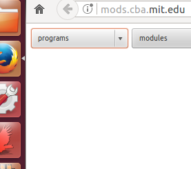
Then we open Mods:
Go to Programs > Roland > mill > MDX-20 > PCB
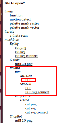
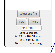
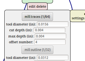
Then the interface to control the milling comes up, where we upload the PNG file, which is 1K DPI, and choose the drill bit, which is 1/64" right now:
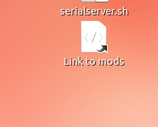
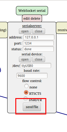
Now it's time to connect the machine to the computer. Open up the "Serial Server" link on the machine's computer at the lab, then click "Serial server - Open" in the mods interface. Now that there's a connection - on the actual machine itself, click the "View" button to take it out of view mode, which would allow you to control it. In the mods interface, put in the X and Y values for the origin point (play with them until the drilling bit is at the right location on the plate for you):
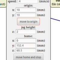
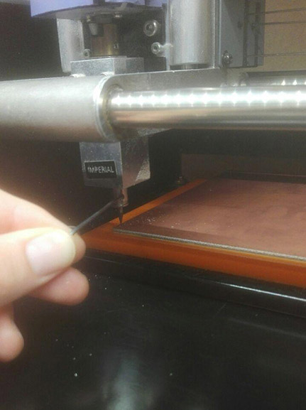
Lower the drill bit using the up and down buttons on the machine, until it's almost touching the plate. Loosen the drill bit holder while holding the drill bit with your finger, and gently put the bit down on the plate. Turn it a little from side to side, to move away any bits of dust underneath it, then fasten the drill bit holder (gently) again. It is now time to calculate the path. Hit "Calculate" in the mods interface:
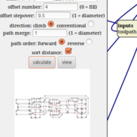
Now it's time to hit the 'Send file' button to print it!
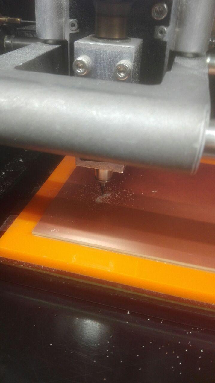
The machine doing the milling:
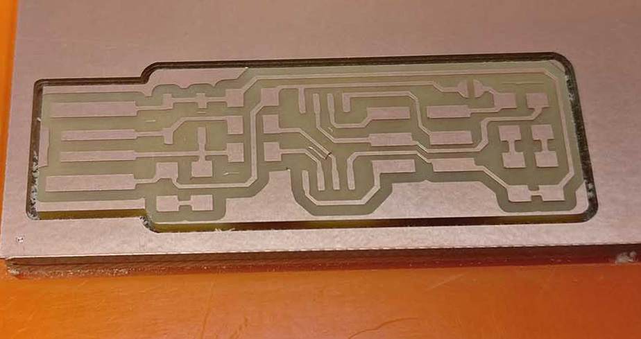
Once the machine is done with milling the circuitry with the 1/64" bit - clean up the plate using a vacuum, change the 1/64" bit with the 1/32" bit, and upload the image for the shape outline of the board. Select the 1/32" bit in the mods interface, and basically just do the same thing. Move to same origin, move drill bit down, loosen, gently put on plate, rotate with finger to remove dust, fasten, calculate, send - same thing.
After the board's traces are milled and after the board's outline is milled, it looks like this:
At the end, take out the base plate, clean it, and take the circuit board out. The machine and station should also be cleaned - don't be a dirty poopy pants!
To solder the board, I used the list of components and directions provided by Brian:
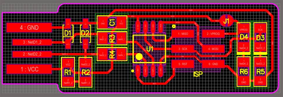
http://fab.cba.mit.edu/classes/863.16/doc/projects/ftsmin/index.htmlThe list of components is already specified at the top of the page. The board schematic I used for guidance is:
For the actual soldering work, I used one of the lab's provided soldering irons and soldering tin wire. Just heat up the copper plate and component, and apply the tin wire.
Each component was soldered in it's rightful place according to the above diagram, with consideration for the right component orientation.
After soldering the components, the programmer looks like this:
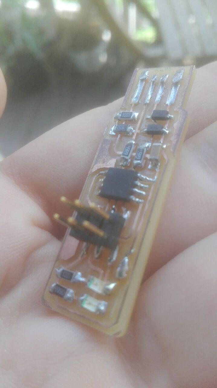
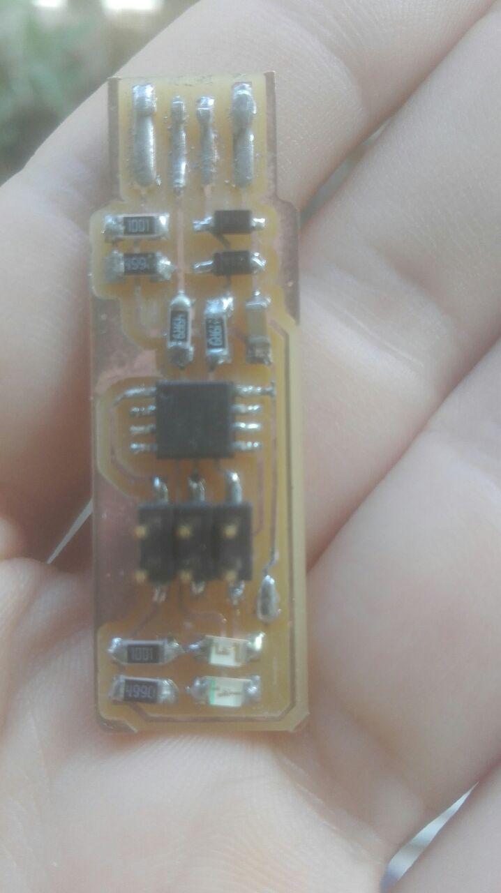
Now that it's soldered, it's time to program it following Brian's walkthrough. I hooked the programmer up to Emma's programmer using a cable strip, and plugged Emma's device into the computer's USB. Install Crosspack, download firmware, build hex file using "make" command, and I actually also had to change the hex file a little - because it initially has Attiny45 in it, but I'm using Attiny85, so just changed that in the file. During this phase, I skipped a step without realizing it, the "make fuse" step, and this ended up complicating things for me since I had to run back and forth between Emma and the workshop and the computer again trying to get the programmer to work and to be fine, but then we both realized the issue is from the "make fuse" being skipped, so I retraced my steps, ran the right command, and after finishing all the steps - plugged my new programmer into the USB and ran the "avrdude -c usbtiny -p t85" command to finally verify that it's all fine.
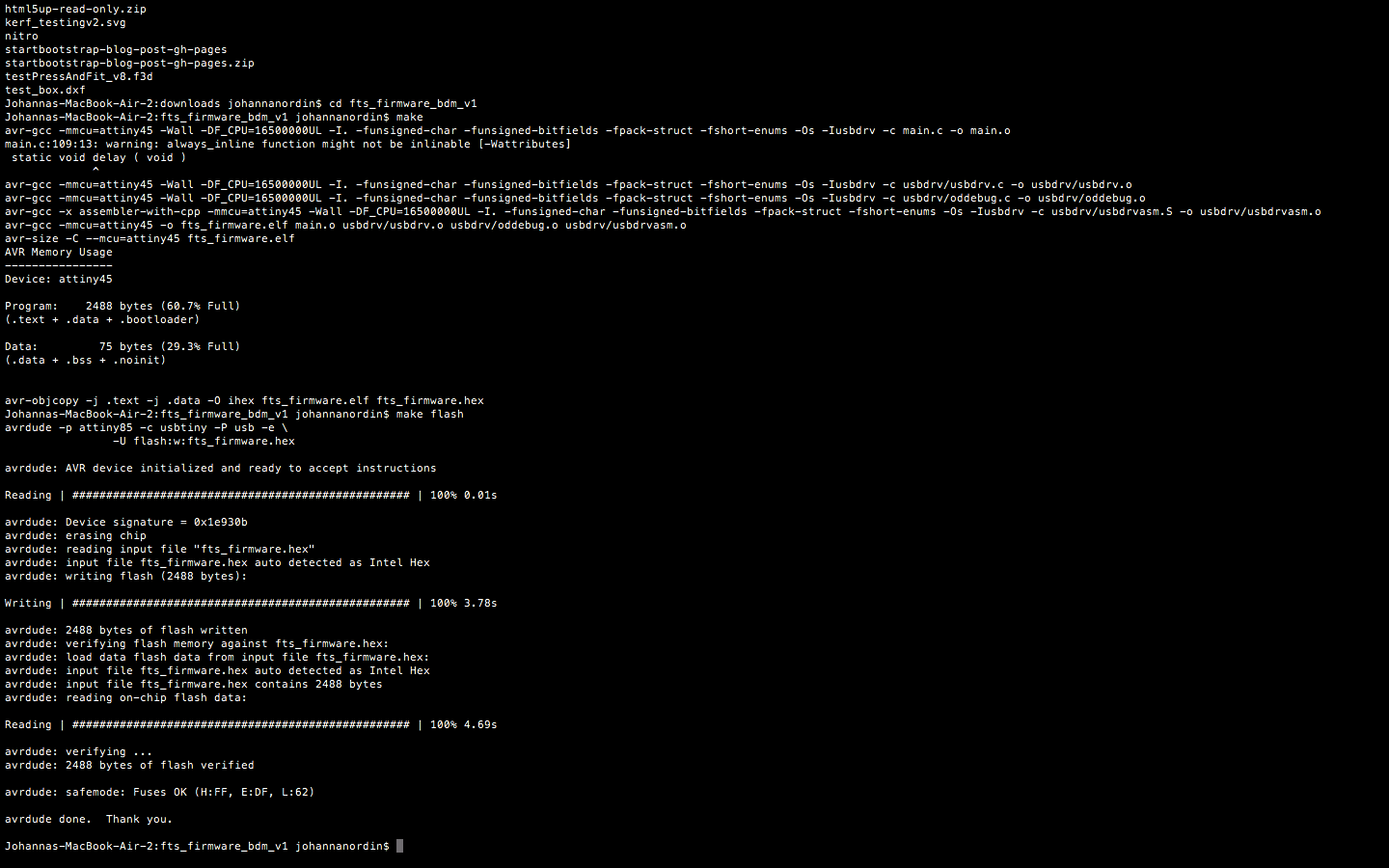
Make Flash:
Make Fuses:
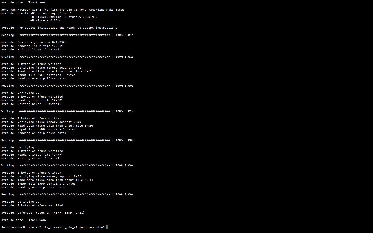
In the end everything ended up working well.
Back home