I'd like to make a modular board, based on the ATMEGA design which has many pins. The modular part comes in with the sensors - I'll be connecting them or disconnecting them via pins and wires, rather than solder them on the board, to allow a modular functionality and multi-purpose reprogrammability and use of the board.
Well then, a good starting off point for this would be to look at the ATMEGA data sheet, and the schematics of an ATMEGA board.
I figure, using the Satshakit as an inspiration and basis for my board is a perfect idea:
Looking at the ATMEGA board and the Hello World board we previously designed side by side:
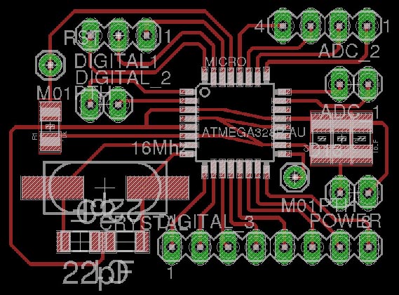
A few interesting notable differences come up. For example, the ATMEGA has two VCC pins. It has two GND pins too. And in general has a bunch more pins than the other board.
Per the Satshakit board using the ATmega328P-AU chip, I reviewed the datasheet of ATmega328P-AU.
Checking the sheet, there seem to have a few ATMEGA type chips, there's one with 28 pins and one with 32 pins.
The 28 pin version has 1 VCC pin and 1 AVCC pin (which I assume the A stands for Alternating). The 32 pin chip has 2 VCC pins and 1 AVCC pin.
Both have the equivalent amount of GND pins as VCC/AVCC. But they have more differences than this - not just a 1 pin differences but 4 pins difference.
I actually should probably check to see exactly which version of the chip I have in the lab, which I won't be able to do until Monday, giving me barely any time to design the actual board.
As a result, I have decided to stay with the ATTINY architecture, for now, but will make an ATMEGA board as soon as possible.
So - now that I determined to use the previous ATTINY architecture, using the Attiny84A chip.
The Attiny84A has only 14 pins, as opposed to 32 or 28, so at best - half of the ATMEGA, at worst 43% of the ATMEGA.
Out of these pins, 2 are completely free, and 2 are used for the LED/button. Since I won't be using the LED/button from the previous design, this leave me with 4 free pins for output, in case I want to.
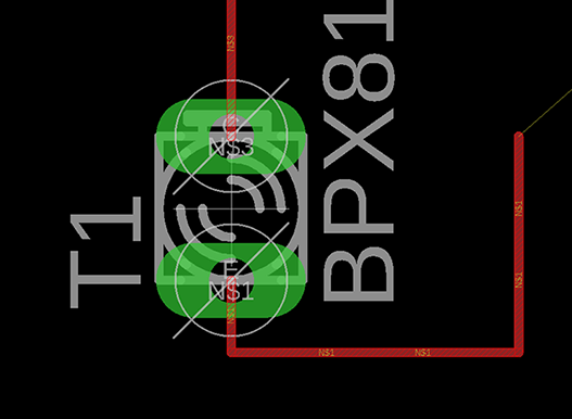
I'm going to use a light sensor for this assignment, and I'm going to redesign the board to have the 4 pins free and connecting to free pins, to which another board with a sensor can be connected.
Maybe even two boards, with a light sensor each. But nah let's just do one this once, to complete the assignment, and make sophisticated boards with multiple capabilities later.
Okay so actually - I've determined that I don't even need to radically redesign the hello world board - just add two more pins for an external connection, to which a light sensor will attach. Simple.
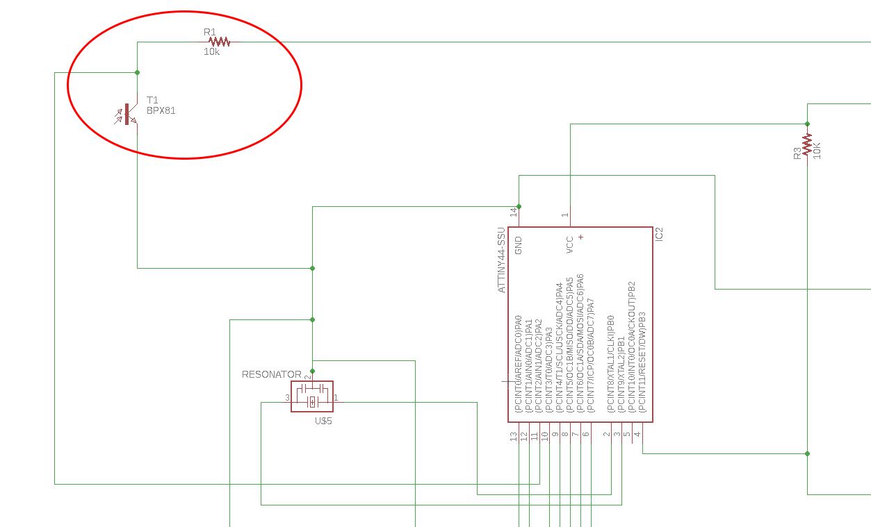
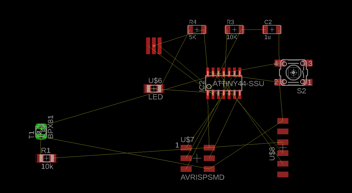
I opened up my schematic from the Electronics Design week in Eagle, and simply added the necessary parts to make a sensor work.
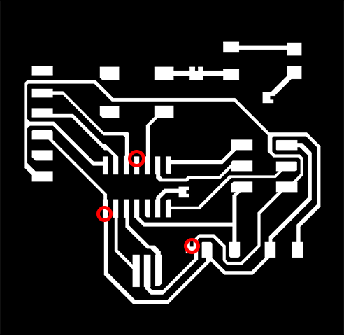
Looking at the sensor configuration in both the schematic and the board plan:
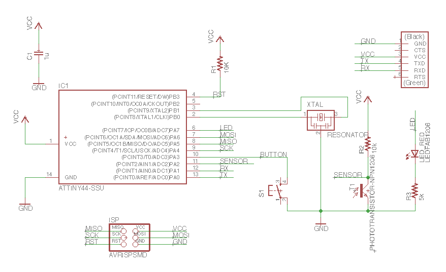
On my already existing hello world board I'll need to add another connection to the PA2 pin and to the VCC coming out of the 6pin connector (either of them, because they both converge anyway), as well as another connection to my resonator's output as it's on it's way to GND.
So it's three vertical pins to add on the hello world board original.
I would need to add three new connection pins to these areas:
I also want to remove the whole led light / button set up going on in the hello world board, since I don't need it, and instead connect some additional pins to it.
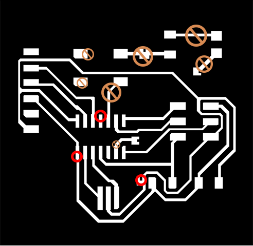
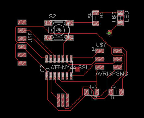
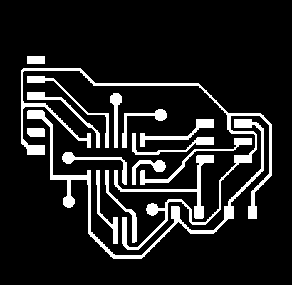
After modifying the original design, here's what the new design looks like:

And of course, I also need the design of the sensor board itself:


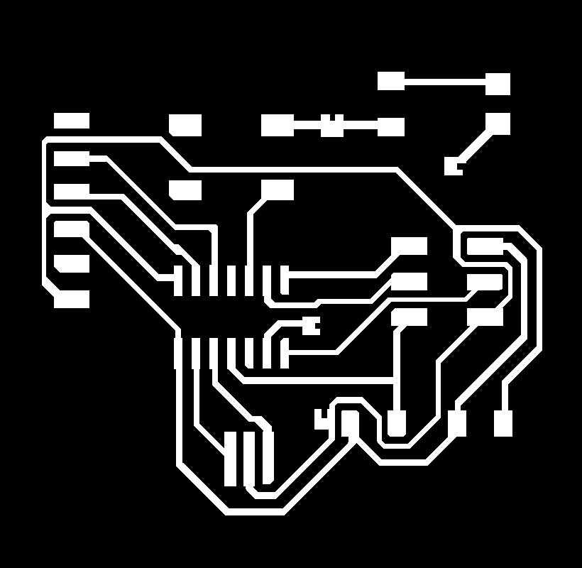
At the lab, I milled the design in the small CNC machine Roland MDX-20, at 1k DPI, everything went super smoothly. Everything went super smoothly during soldering too, and I also soldered some connectors to a few wires to properly hook up my sensor to the chip. I ended up with:
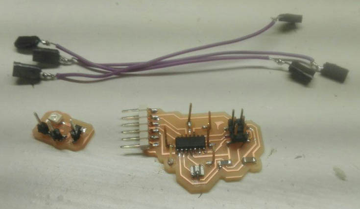
I hooked it up to my programmer, burned a bootloader via the Arduino IDE, it all worked perfectly.
I also ordered an FTDI cable online, so that I can connect it to my USB and monitor the serial, to get the input from the sensor.
I wrote the code:
Programmed the board, then hooked it up to my FTDI cable and to the sensor, selected the right Port, and opened up the Serial console to see my inputs:
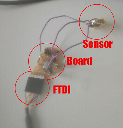
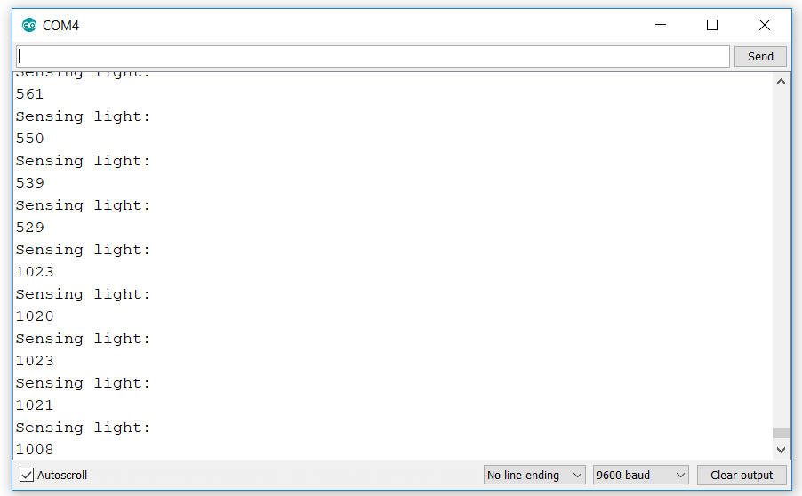
Ta da!
Below are the code and schematic of this board for download:
CODE
SCHEMATIC
Back home