This is part one of the two week assignment.
Go to part 2
We decided to make a karaoke machine.
My labor division was to design the machine itself in Fusion 360, for CNC cutting and laser cutting.
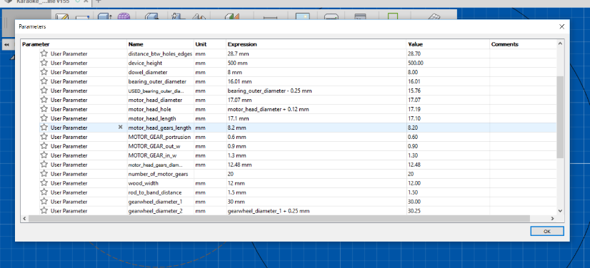
Because this relies on so many different real life objects we're going to be working with, the entire design is parametric, with about a billion different parameters I measured and calculated:
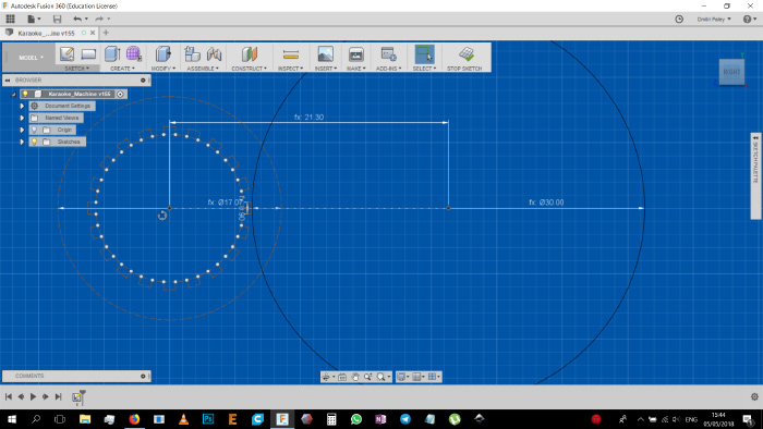
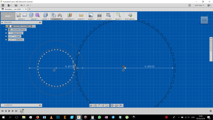
Because we're using a custom gear with the motor's gear, I needed to make some calculations for how many gears and their size to design. Considering that the final gear wheel diameter should be approximately 3cm, and having already measured the inner space between gears on the motor gear, calculating this was fairly easy. With the creation of the following variables, based entirely on the motor's gear itself:
A = width of each gear tooth = 0.9mm to 1mm (difficult measure but small enough margin to dismiss)
C = circumference of the wheel = 39.21mm
R = radius = 12.48 / 2 = 6.24mm
N = number of gears = 20
I devised a quick formula to calculate how many teeth I will need on the big gear wheel I'm designing.
First I checked how much of the circumference the gears are occupying (the ratio), simply by:
(A * N) / C = (1 * 20) / 39.21 = 0.51 roughly
So the ratio of gear width to gear wheel circumference is 0.51.
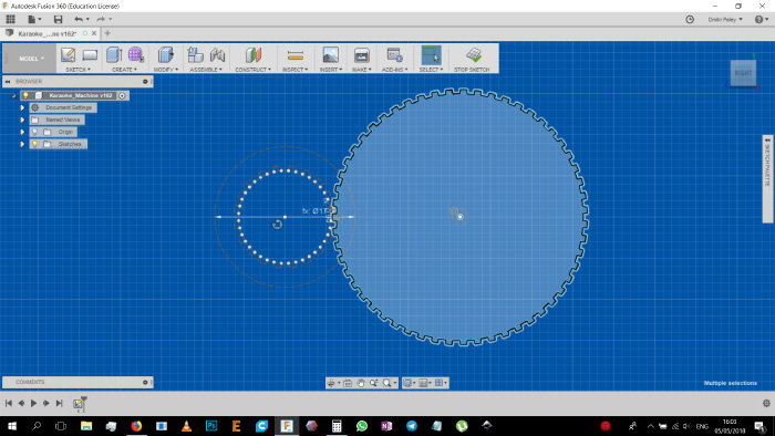
With this, and with the designed gear wheel being with a 3cm diameter + the length of the gear (0.5mm), so 3.1cm diameter or 15.5mm radius, and with 0.9 for the width of the gears (because I want the designed gear wheel's gears to be thinner for fitting purposes), the calculation was:
C = 97.39
A = 0.9
(A * N) / C = 0.512 > A * N = 0.512 * C > N = (0.512 * C) / A
N = (0.512 * 97.39) / 0.9 = 55.4041
Which translates to roughly 55 teeth on the gear wheel. With a few additional minor numerical adjustments to make it work I got to designing the gear wheel.
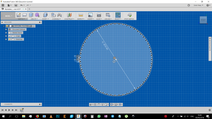
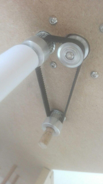
However, later at the lab we actually found that the gear, while functional, is not the ideal solution. So we re-devised a new solution which involves a small belt and another motor gear wheel, basically a makeshift last moment fix, but it worked much better:
Anyway, back to the process:
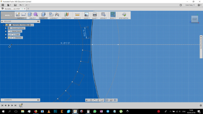
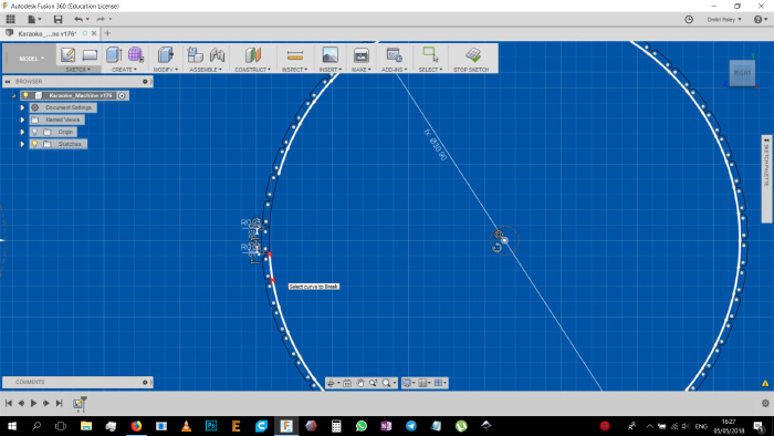
The rest of the process was more straightforward, with just using all the parameters I have created in advance, and just visually designing the machine:
Using the parameters I established I started making holes and grooves in the sketch so allow the motor to stick it's head in, be screwed in with it's 4 screws, and to allow the machine parts to be connected to one another.
.jpg)
A few slot holes in the side to allow for the motor holders to stick in.
.jpg)
The motor holder itself.
.jpg)
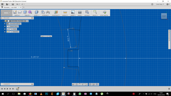
Dog bones in order to have the connecting parts fit in properly.
.jpg)
.jpg)
A shape to get the paper comfortably sliding from and to the front & bottom of the machine.
.jpg)
And the rest of the design is basically the same.
.jpg)
.jpg)
.jpg)
.jpg)
And the actual machine when constructed and put together:
.jpg)
.jpg)
.jpg)
.jpg)
And this last show is of a small flaw in the design, where the other end holding up the rubber band had to have also been re-designed last moment and thus came out a little crooked (but fully functional):
.jpg)
And this is the end of the first machine making week for me.