Because this is a 3 page assignment, for simplicity, all the design files are right here on the front page.
Download here:
The 2.5D and the 3D files RAR archive
Note - because the 2.5D and 3D design files are too heavy for upload in the repo, they're on my Google drive, and the link downloads a Rar of them.
Now - onto the process. First up - 3D! Just like real life.
I'm using Fusion 360 for this.
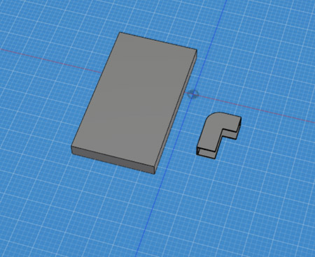
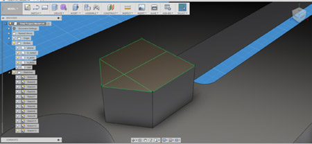
As always, I begin with the smaller details of functionality. First, I make a sketch, and sketch out the little device holders (just one of them, I'll be duplicating them later).
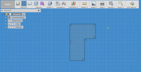
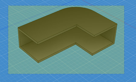
I close the sketch, and extrude the bad boy out of there:
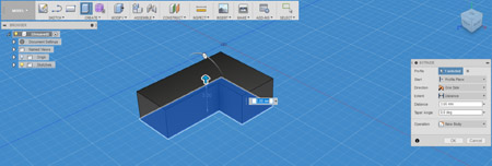
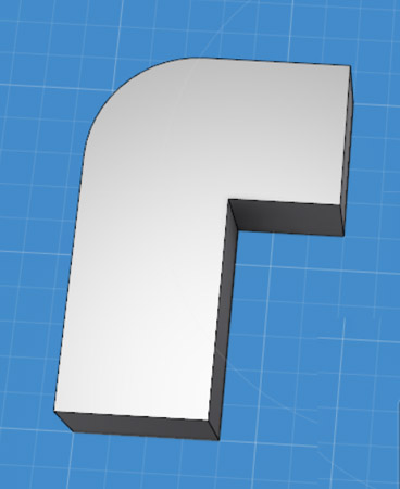
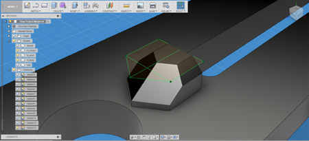
Then turn it around and give it a little Fillet on the corner:
I play around with the Fillet radius for a bit until I settle for 3mm. Looks good!
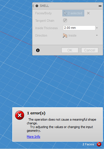
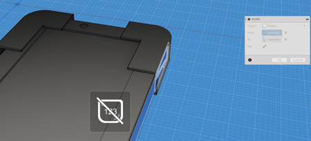
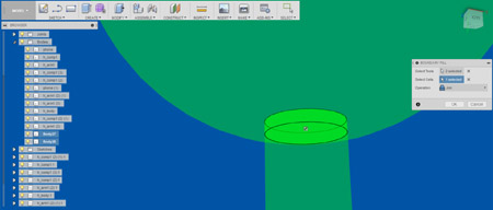
I wanted to hollow it out using the Shell command, and was kind of looking forward to it, but it looked like I couldn't do it when selecting two faces, nor when just selecting even one:
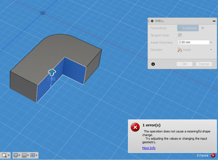
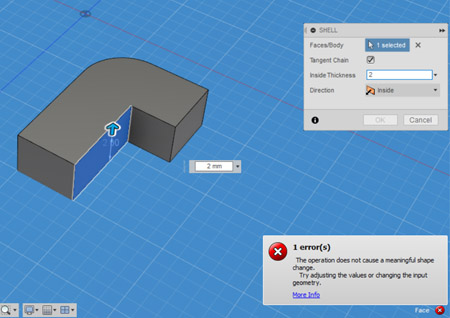
But it turns out I was just not paying attention to the Inside Thickness parameter:
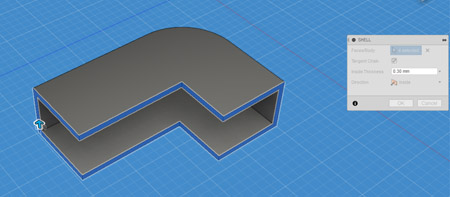
Remembering that the thickness of my component is just 3mm, I again selected all the faces I wanted to shell and set the shell thickness to 0.3mm which looked good.
At this point I also realized that I'm modeling components which are far too small and thin, but figured I'd already go with it. Since Fusion 360 is a parametric CAD, I can probably simply scale the model up later on quie easily.
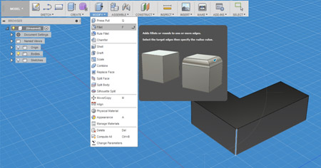
I selected the entire model:
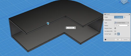
Then applied the Fillet Command to it all, with a 0.05mm thickness.
Except NO - because apparently opening the Fillet command de-selects the entire model.
Probably because all the faces were selected too.
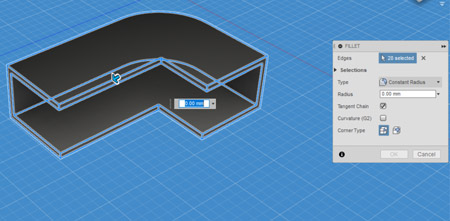
I dragged the mouse over the model again in Fillet mode and selected the whole model, and this time it only selected the edges and allowed me to make the Fillet:
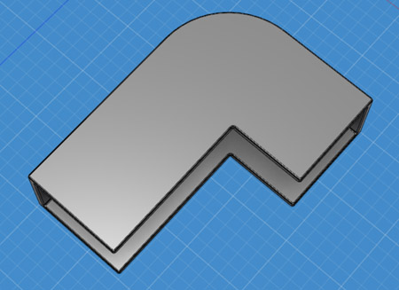
I got into a nice view to have a look at the beautiful model, and saved it.
To reward myself for a job well done I sliced a piece of cake, made some tea and moved myself to the super cozy work room.
To complement my mobile device holding component, I modeled a quick mobile device. Sketch > Extrude > Fillet the edges.
The rectangle dimensions are 32 x 18 in the sketch (to account for the common 16 x 9 mobile dimensions), and I added a few extra details to make the phone look more pleasurable.
Because my holding component is 3mm thick, and has a 0.05mm inside wall, the largest object that can fit inside it is 2.95mm thick. So for the mobile device model's thickness (Extrude) - I set the value to 2.9mm for a snug but still comfortable fit.
Viola!
I moved the phone model over to the holder model to check the fit:
Aaand it's too tight.
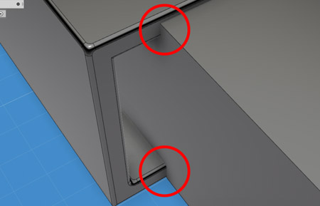
I noticed I miscalculated the necessary thickness, slightly, only accounting for one 0.05mm reduction off of the 3mm thick holding device, instead needing to account for two reductions (one per wall) to a 0.1mm total. But that's still not accounting for the big difference, so now I need to learn how to measure parts of a 3D body.
I found on the AutoDesk Fusion 360 forums that the necessary step is to "select the face and use Inspect-Measure", so I did that. I used the Mesure command in the Inspect menu and selected the entire body. The dimensions I got are Area and Loop Length, which is cool but not entirely helpful.
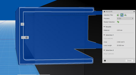
Next I selected only two parts - the top and bottom most edges. This actually gave me the distance between them, which shows 3mm.
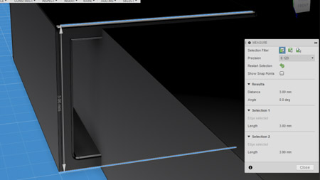
So that's correct. Next I measure the distance between the inner most edges, and it turns out it's 2.4mm. That's the area inside I have to work with, not 2.9mm. Lesson here? Watch your goddamn numbers, and try to remember how thick you *actually* make your shell walls. Apparently the shell walls I made were 0.3mm thick, not 0.05mm.
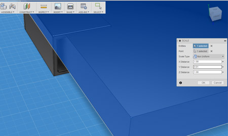
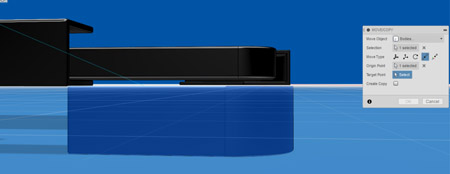
So I go back to the phone and shrink it down to the thickness of 2.35mm to leave a 0.05mm wiggle room inside. I consult with Google and to shrink a body I just need to go to the Modify menu and select Scale. I go to the command, select "Non Uniform" in the Scale Type and scale the model on the Y axis. If the phone is 2.9mm thick, and I need it to be 2.35mm thick, then X * 2.9mm = 2.35mm, so X = 2.35mm / 2.9mm which is 0.81 (approximately).
I check the fit again, and it's beautiful!
But still a bit too snug. So I shrink the phone on the Y axis by another 10%.
Okay, time for decoration!
I sketch on top of the phone a rectangle (for the screen) and a circle (for the little early iPhone circle button), and extrude them 'into' the phone, with the mode 'Cut' to pronounce the details on it.
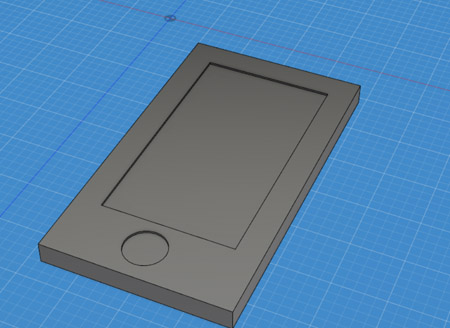
Fillet edges to taste, and I also added a little camera to the front of it:
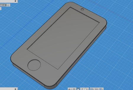
Beautiful! Looks like a convincing enough mobile phone :)
Now it's time to turn just one holding component yo four of them!
I try the good ole CTRL+C and CTRL+V technique - and it works!
After copying and pasting the body, I get a new body in the same exact location.
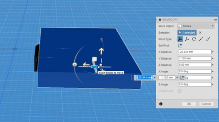
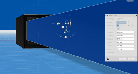
Moving it around and fiddling with the Move/Copy command, I find a nifty little option called "point to point", which lets me move a body to another location by selecting one of it's points and selecting the other point it should be at exactly.
Voila! both pieces at exactly the same height now, which really helps place things around.
I proceed to procuce three copies of the holding component, and place them on each corner of the mobile phone.
I also make them a little bit more narrow, reducing their width by 15%.
TA DA!!
It looks pretty good, but It's still not smooth sailing in terms of getting every object to a precise position. Right now however it's far past midnight, and so I'll continue this tomorrow. I saved my project, and... this is turning out to be a lot of fun!
The next day
It's 1:10PM, I'm making my incomprehensibly good slow cooked meatballs, and this is the perfect time to proceed with modeling this... model. I'd like to start by positioning all my bodies a little more elegantly, and think I can do it using the Align command from the Modify menu. I select the Align tool, and see I need to choose two objects. I select the inner face of the holder, and then the side of the phone. It snaps perfectly together.
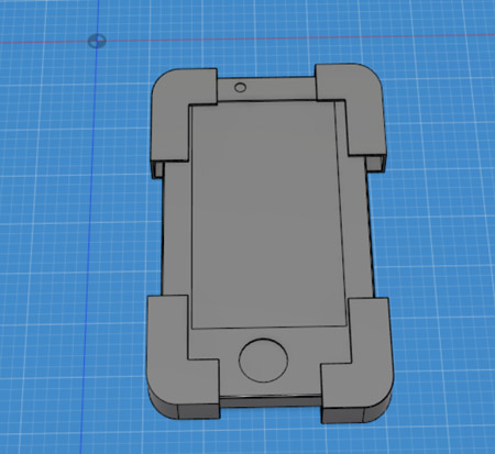
I align all the components to fit as tight as they can around the phone. The end result looks like this:
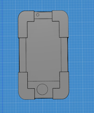
Perfection.
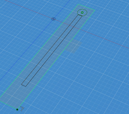
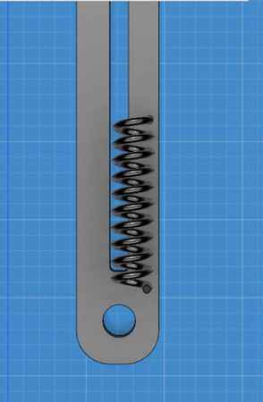
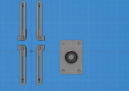
Now it's time to make the phone body invisible, and add another sketch for the springy rail components which will hold the holders (I gotta come up with a better naming convention) and ultimately make this whole object completely dynamic in the range of device sizes it can hold.
This component is basically a long flat stick with a rail in the middle and a spring at the back of it.
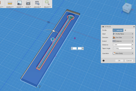
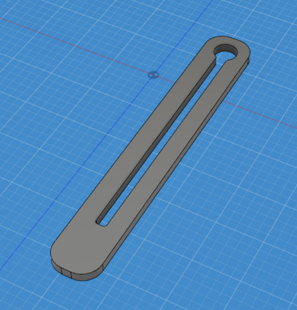
And adding a last hole for a pivot:
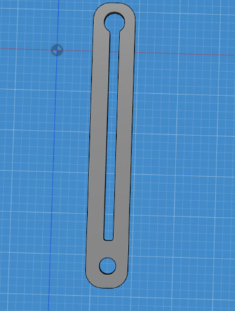
It basically looks like a chain lock, turns out.
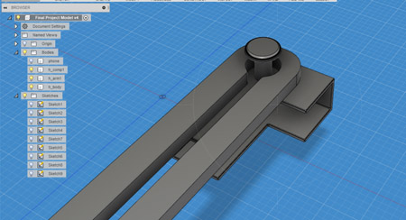
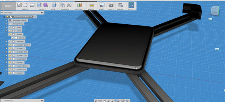
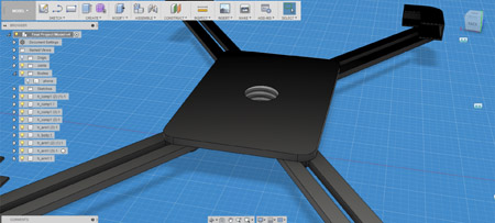
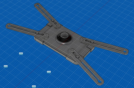
Now that I have this component, the next step is what it attaches to. Don't worry, it's all gonna come together real nice very soon. It's just a big rectangle with four cylinders extruding out of it. I also used the Create > Thread command to make a screw thread, since I plan on screwing in a big stick in the middle of it.
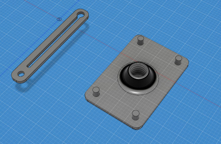
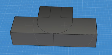
At this point I decide to delete three of the 4 holding components I made earlier, because I actually need to attach them to the holding arm, and for that I need to make a slight change to them and to again change their location, and it'd be much easier to just do this with one object and remove the rest. After making the necessary changes the component now looks like this:
And fits in super beautifully with it's holding arm:
I also tried to make a spring coil to demonstrate the fact the model will actually use a spring coil or rubber band to create tension and actually hold the mobile device given to it, but I got frustrated with trying to rotate and orient it properly, as well as with checking whether or not it can stretch one way or another, so I decided to drop the idea for now.
Instead I won't make neither a spring coil nor rubber band, and just say they're there, it's not a hard concept to grasp and certainly doesn't really need modeling.
At this point I kind of want to add a little fancy looking shape that would be the holder of the rubber band or spring coil in the future, and trying to change the following shape to be a little more pyramid-ey:
I discovered that using Modify > Chamber gives me a result kind of similar to what I wanted. It's not perfect, but I got at least two more models to make, so this will have to do. And after fiddling with it a little but, It actually looks really nice, and definitely good enough for me
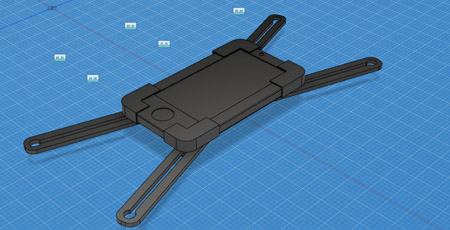
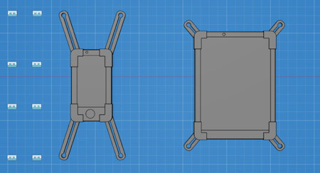
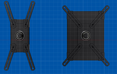
I now made three copies of the arm + holder bodies and rotated them to their right orientation. I found on the Fusion 360 forums how to effectively "flip" a body, and turns out I can use the Create > Mirror command for that and not have to frustrate myself by doing multiple rotations on each. So I did just that and I now have a beautiful set of 4 mirrored components.
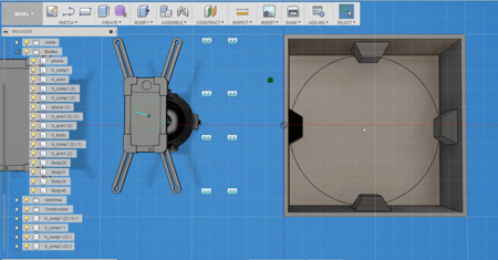
I then used the Assemble > New Component to make each object a component, so that I can joint them together, and then Assemble > Joint to join them together exactly as intended.
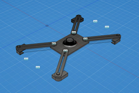
And now to put the phone again in the hands of my device.
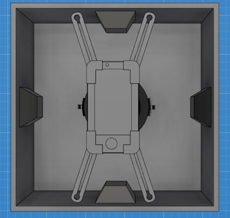
Step one, put the thing in the middle of the thing:
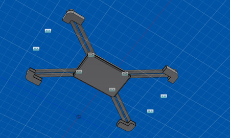
Step two - find out that the way I set things up, the holding components actually intersect with the rectangle that's holding them, and they have no way of actually holding the phone.
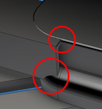
Sigh. It looks like maybe the best way to fix this is to go back in time (a nifty feature Fusion 360 has) and simply change the thickness of that rectangle, but I have so many operations in the record and absolutely no idea even remotely which step that is.
So I end up making another sketch, with the purpose of making an Extrusion into the rectangle, and to just cut a chunk of it off. It gets the job done.
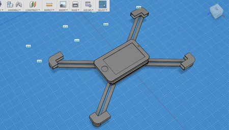
After scaling the phone up by 125% (just it's height and width, not it's thickness), I set the whole thing up again and this time it measures perfectly and fits together like Al and Peggy Bundy.
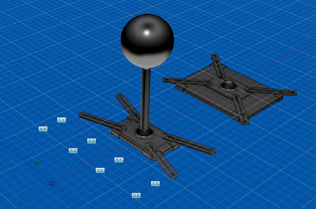
I also made a larger mobile device model, a tablet, to demonstrate how the holding mechanism would actually work dynamically on different devices:
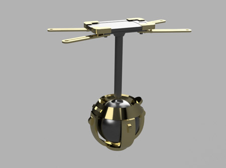
After saving the project, I'm moving on to the big screwy stick. It's simple enough - it's a stick, and it's 50mm long.
Voila.
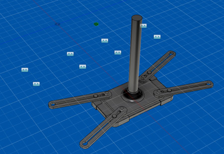
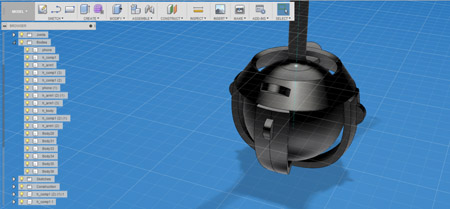
Now a ball - coz that's what the stick connects to. And using Create > Boundry Fill I'm cutting out some intersecting components to delete them:
And I combine both the ball and the stick and give their connection a pretty fillet.
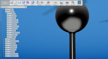
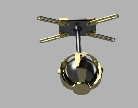
Now to make the little ring and the horeshoe holders which will house the wheels as well and basically will control the movement of the ball. The ball, by the way, is 30mm in diameter.
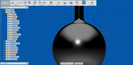
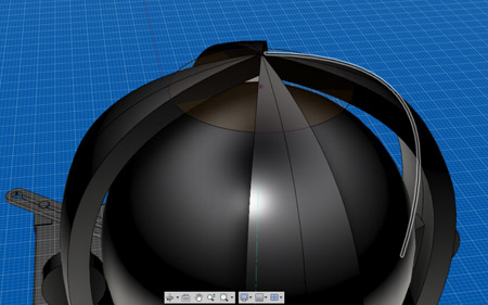
To make the slightly slanted ring I make a simple sketch of a crooked rectangle, and then use the Create > Revolve command, which is really awesome.
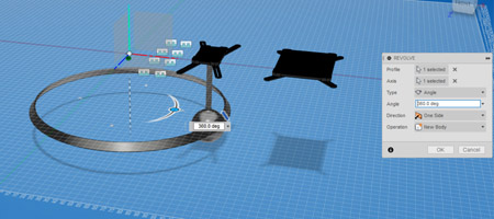
Turns out it's way too big, and I'm not too sure why.
After fidgeting with the darn thing a little, I realized that it's because of the axis I selected. I selected the Y axis, which is quite far away from that area, and it made a perfect circle around that axis, with the radius of my sketch from the axis itself. So I need a more local axis basically. To fix this I decided to try the Construct > Axis Through Cylinder command, and put the axis right through the ole ball & stick from earlier. It worked.
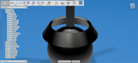
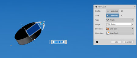
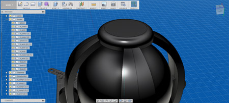
Using the same technique, I also made a little wheel. The only difference is I used the edge of the rectangle when doing the Revolve command as the axis.
Now the Horseshoe body:
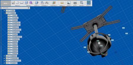
And a copy of it, to the end result looking like this:
A few final touches:
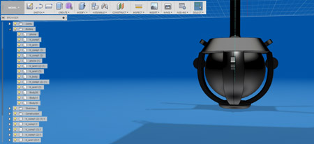
Now I am just about almost done!
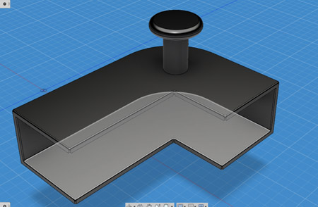
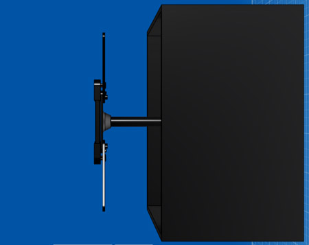
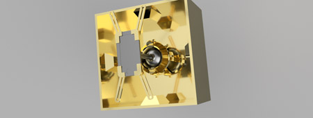
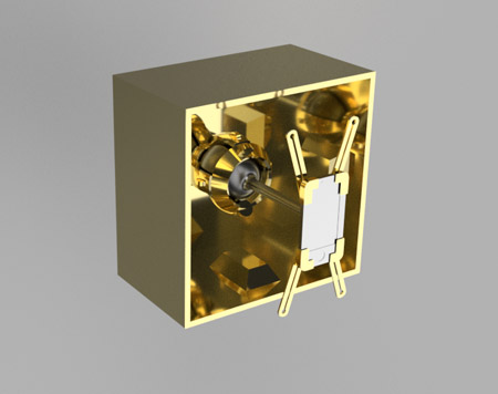
The ball holding device attaches to the back of a box, which acts as the house of the entire mechanism, and the walls of the box hold little pockets in which electric motors are housed, each motor attached to each corresponding wheel with a rubber band for rotation.
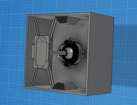
Box - 100x100x60mm and using Modify > Shell to make it hollow, and add the little motor pockets using extrusion:
And the full whole thing combined:
Finishing touches for real!
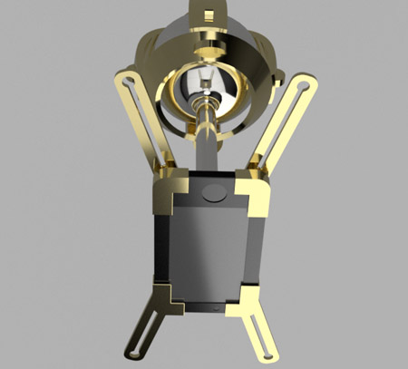
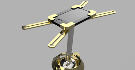
Giving the model it's material, I decided on Gold. Pure 24 karat gold. Because I deserve it (sparkles).
The rendered version:
And now that I see how cool it is, I changed the materials up a little again, just to make it really the vision.
Final render!
MOVE ON TO THE NEXT PART - 2.5D