First things first! Watch the video how i implemented the interface in the project.
Ready this page brings you back in time a few days ago. At the end of this page i will describe the working of the interface.
Finally! Yesterday the i2c OLED arrived!
And now, after 10 minutes of fiddling, i have it working!
What i did:
-
i’m using one of the satshakits that i made during the networking week. Main reason is that this kit 100% arduino uno compatible. So i hope to have less issues with libraries (and i did!)
-
connecting the ftdi, see networking week to the satshakit.
-
following this page on Instructables, named “OLED I2c Display With Arduino”, connected pinA4 to SDA of the oled, and pinA to SCL.
Connections for the OLED
Satsha OLED vcc vcc gnd gnd pinA4 SDA pinA5 SCL -
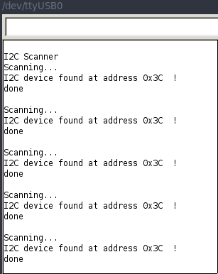
To start, we need to find the i2c address of the display. To get this, I use a quick i2c scanner uploaded to the arduino. The scanner code can be found on http://playground.arduino.cc/Main/I2cScanner. Copy and paste the code into your arduino IDE, build and upload, and fire up your serial monitor.
-
installed libraries (i did it from within the arduino-ide)
Library url SSD1306 library https://github.com/adafruit/Adafruit GFX library https://github.com/adafruit/Adafruit-GFX-Library -
In your arduino IDE, check the examples menu and locate the i2c sketch found under Adafruit SSD1306. I uploaded the sample sketch for ssd1306_128x32_i2c
Bummer!
Then i realized the display is not 128x32 but 128x64. So uploading the other sample: ssd1306_128x64_i2c
I then got an error during compiling:
ssd1306_128x32_i2c:54: error: #error ("Height incorrect, please fix Adafruit_SSD1306.h!");
#error("Height incorrect, please fix Adafruit_SSD1306.h!");
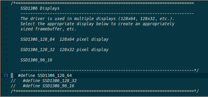
So i looked up the library and changed the line according to my device (uncommenting #define SSD1306_128_64). Compiling and uploading went fine, but the display appeared blank.
While searching for an answer i downloaded the same script from another source, compiled and uploaded it and it went fine. So first the result. Look specially to the resolution, and compaire it to the video above.
I diffed the 2 sketches and one of the first lines immediately took my attention:
<   display.begin(SSD1306_SWITCHCAPVCC, 0x3D);  // initialize with the I2C addr 0x3D (for the 128x64)
---
>   display.begin(SSD1306_SWITCHCAPVCC, 0x3C);  // initialize with the I2C addr 0x3D (for the 128x64)
so: wrong i2c address! After changing the address, everything compiled and uploaded just fine, sample image is fine.
then wanted to use some other libraries and test it with a actual input. So i hooked up a Phototransistor and resistor, hooked it up the satshakit, found a sample with the U8glib libraries - Arduino Monochrom Graphics Library for LCDs and OLEDs. It’s the output of the phototransistor in waveform format.
I like this library more because it looks less fatty then the adafruit ones:
To explain the code a bit:
void loop(void) {

// read the value from the phototransistor, connected to gate A0, outputting values between 0-1023.

  analogInValue = analogRead(analogInPin);

// map the value on the y-axis. Values between 0 - 1023

  y[x] = map(analogInValue, 0, 1023, HEIGHT-1, 0);;

  u8g.firstPage();
  do {
    drawY();
  } while( u8g.nextPage() );

  //delay(10);


// stream the x-axis from left to right, and rebuild at the end.


  x++;
  if(x >= WIDTH){
    x = 0;
    clearY();
  }
The actual code for this visualisation:
//Set the OLED display
#include "U8glib.h"
U8GLIB_SH1106_128X64 u8g(U8G_I2C_OPT_NONE); // I2C / TWI

const int WIDTH=128;
const int HEIGHT=64;
const int LENGTH=WIDTH;

//value and pin for the LiFuelGauge Pin

const int analogInPin = A0;
int analogInValue = 0;

//clear and draw for the oled screen

int x;
int y[LENGTH];

void clearY(){
  for(int i=0; i<LENGTH; i++){
    y[i] = -1;
  }
}

void drawY(){
  u8g.drawPixel(0, y[0]);
  for(int i=1; i<LENGTH; i++){
    if(y[i]!=-1){
      //u8g.drawPixel(i, y[i]);
      u8g.drawLine(i-1, y[i-1], i, y[i]);
    }else{
      break;
    }
  }
}

// setup for oled and serial

void setup(void) {
  x = 0;
  clearY();
  Serial.begin(9600);
}

void loop(void) {

  analogInValue = analogRead(analogInPin);

  y[x] = map(analogInValue, 0, 1023, HEIGHT-1, 0);;

  u8g.firstPage();
  do {
    drawY();
  } while( u8g.nextPage() );

  //delay(10);

  x++;
  if(x >= WIDTH){
    x = 0;
    clearY();
  }

  Serial.println(analogInValue);
}
Gaugemeter code for my final project.
For my final project i want have a nice interface for the battery status while charging. I found this well documented page on Gauge Meter using Potentiometer that i want to use.
The interface explained
When the device is powered, you should first get a splash screen. I tested it, it’s working and already half in the code.
When there is time i will look if i can use the animation of the project to replays this initial splash screen.
After the splash screen the device is ready to measure the ice. So it’s waiting for an impuls hammering. Once the hammer hits the ice and the piezos pickup the signal, the atmega is processing the data and finally give a value of the thickness of ice. That value will than being displayed on the oled display.
When you charge the device, the screen will look like as a gaugemeter that visualize the status of the battery.
Once unplugged, the display brings you back to the ice measuring interface after a first knock (as shown in the video).