| This week | |
|---|---|
| Presentation computer-controlled cutting | http://academy.cba.mit.edu/classes/computer_cutting/index.html |
| video of the review (computer-aided design) | https://vimeopro.com/academany/fab-2018/video/254791088 |
| video of the lecture | https://vimeopro.com/academany/fab-2018/video/254791304 |
| video of the recitation on How to make (almost) anything usable | https://vimeopro.com/academany/fab-2018/video/254518604 |
| Assignment | Used software | Files/Downloads/links |
|---|---|---|
| group assignment | characterize your lasercutter, making test part(s) that vary cutting settings and dimensions | http://archive.fabacademy.org/2018/labs/fablabamsterdam/lasercut/index.html |
| B/W fablab logo | Inkscape | fab-academy-logo-bw.svg |
| parametric design part 1 | Freecad | vierkant.fcstd |
| parametric design part 2 | Freecad | pressfit.slot.fcstd |
| dxf for lasercutting | Freecad/qcad | pressfit_final_2.57.dxf |
cut something on the vinylcutter
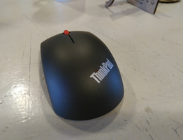
First: Meet my mouse!
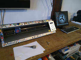
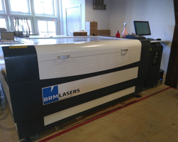
At Fablab Amsterdam we have a Roland GX-24 lasercutter. Creative Learning Lab of the Waag also has 2 Silhoutte Cameo lasercutters. I’ve work most on this cameo till now. Mainly because there is a nice inkscape plugin that enables direct printing/cutting. But for this lesson the Roland is used.
I decided to make a sticker of the fablab logo, so a 3 color one.
I used a back/white fablab logo as a starting point. It was imported in inkscape. I decided to make them colored in inkscape, place markers in colors for later on, when i had to put the resulting vinyl stickers on the transport layer.
![]()
![]()
After making the artwork i separated them by color.
![]()
![]()
![]()
Now the artwork is ready to send to the vinylcutter.
On the lasercutter the used vinyl was put in place from the back, by adjusting the handle on the right. The rollers were slided in the right position to match the vinyl.
As settings i used: 90gf for force and 1.00cm/s speed. Then the test button was pressed to run a first test to see if these setting were correct. Adjust these settings by pressing Menu and use the up, right and down keys. Once done press enter.
If you want to change the origin, use the direction keys to put the knive in the position you want to be the origin and press Origin.
But first the test cut:
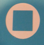
It looked like a perfect cut. The circle came out real propper, leaving the inner cube on the bottom layer.
Now it was time to do the actual vinyl cut. After loading the artwork in illustrator, checking the dimensions (because exports from inkscape are not always in the same dimensions as the original inkscape artwork - see my experiences with exporting dxf for use on the lasercutter). In this case it were svg files and the dimensions were correctly imported.
For each color vinyl i first did a test, with the settings that were used during the initial test (90gf-1.00cm/s). After the test the dimensions of the vinyl on the machine were imported to inkscape. You do this by opening the printer setting, selecting setup, then preferences. Now you see the selected printer, in this case the roland, and it gives you an option to get the cutting area from the machine by pressing get from machine. By pressing print the file is send to the roland vinylcutter.
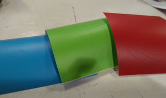
While the vinyl cutter was busy with the green vinyl, i noticed that it was cutting twice. It turned out that the outline was not 0.01mm in illustrator, but 1mm. The other artworx were just fine. Another leason learned:
First check if there is enough material before you start to design
It turned out that there was no more green vinyl, so i had to deal with the 1mm double cutted end result.
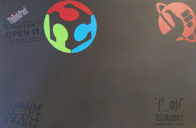
The weeding of the stickers was quit easy, except for the green vinyl. At 2 places the vinyl was not properly cutted, so i needed to weed from the second cut, instead of the inner one. You see it on the picture below when it was put on the laptop.
Anyway: a transport layer was used to transfer the stickers to my laptop. For that all 3 colors has to be placed on the transport layer. The markers were used to place them in the right position.
![]()
![]()
![]()
Unfortunately one of the green markers came loose from the layer, but since the logo is a circle it was not to hard to place the green sticker in place.
Here you see the 1mm double cutting problem on the inner green part of the sticker

A knive was used to remove the 1mm flubber from the sticker. Here you see the end result.
design, lasercut, and document a parametric press-fit construction kit,
accounting for the lasercutter kerf, which can be assembled in multiple ways
first try. Import a dxf i found into freecad and making a sketch out of it.
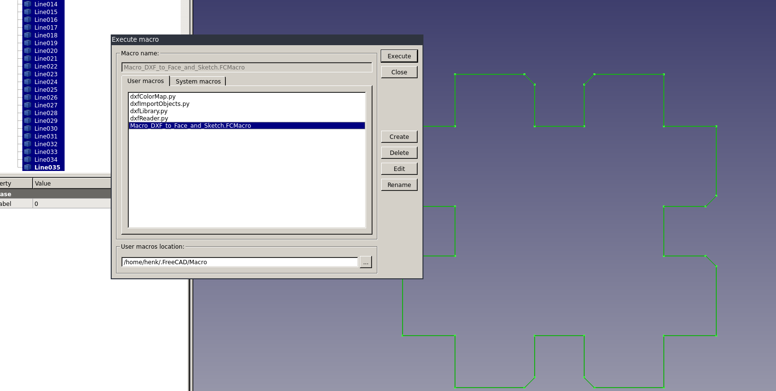
A macro in freecad was used to make a sketch from a imported dxf file. It actually worked! But since i had to make the sketch myself the file was deleted and i started working from scratch. Anyway it was good to find this macro, because i learned a lot about freecad and how it deals with macro’s and workbenches. And it was a kind of understanding what is possible with freecad, that is discovered during the journey. And that was a journey where i felt completely lost several times.
At first i tried to learn freecad the hard way, by starting to do and understand everything at once. Impossible! During the whole process i even forgot to use my fresh bought mouse, so what about all these news things happend in freecad? It was to much. So during the days/weekend spend on managing freecad and 3d-design, i deceided to do go and set goals how to learn freecad another way. I will try to do it step by step during the next couple of week/months. Set a smaller goal to learn and discover freecad step by step.
And the first step this week was to learn Parametric design. What you see here are the 2 end results:
To come there was a long, confusing and time consuming process.
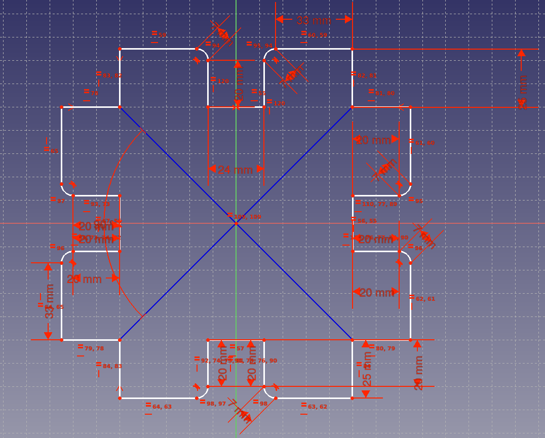
Above you see the first try. What i tried in this design was to make a lot of contraints and trying to controll them to get a design that was parametric. What i learned was that is was to much. To much to simply modify afterwards, so not parametric. To many contraints makes it difficult to be parametric, you build in to many dependencies. But that i know now. I continued and made even more constrains to get the sketch “more parametric”, but that didn’t work :(
Finally i give up on the stuff i made till then. I decided to start from scratch, all over again (what i did a couple of times this first week, and i became very frustrated with Freecad!
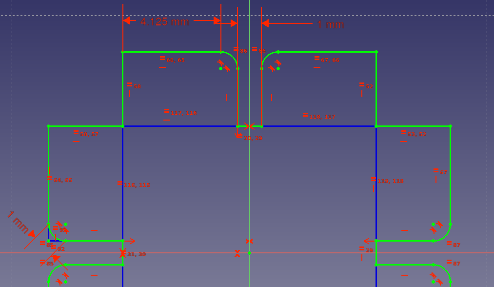
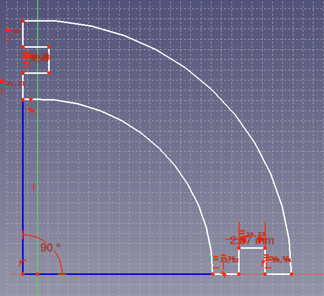
Here are the developments with the second try (or 3th, 4th ..). The workflow became clearer to me.
- make a sketch
- decide on how to implement the parametric part
- search and mark all equality contraints in the sketch
- carefully give as less as possible a “fixed length”
- make the sketch fully constraint
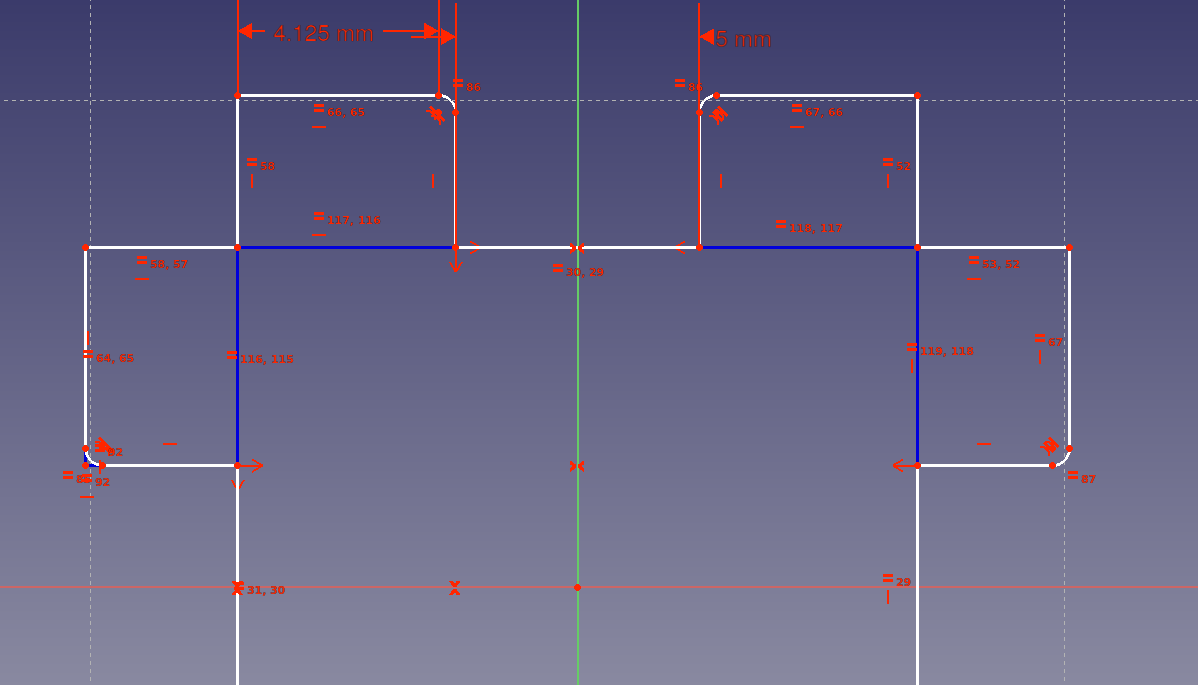
In between this journey i alsways tried changing the parameters to see what was the result. Many times of cources the sketch went nuts. To go back in the proces and start over again and again, was a time consuming proces. But now i have a way better feeling how to work with sketches in freecad.
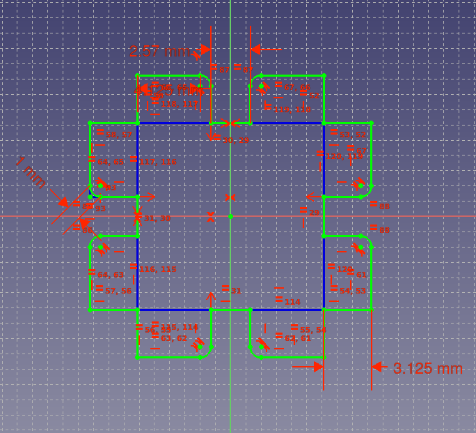
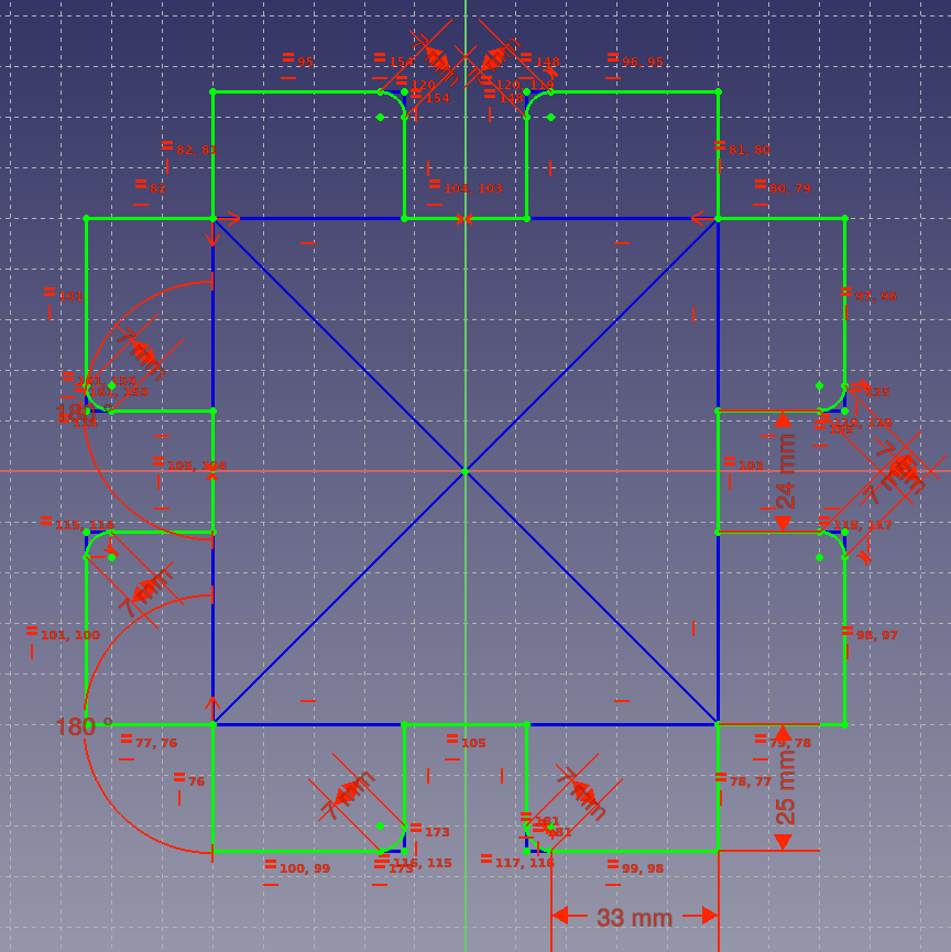
Here you see the final sketch, fully constrained:
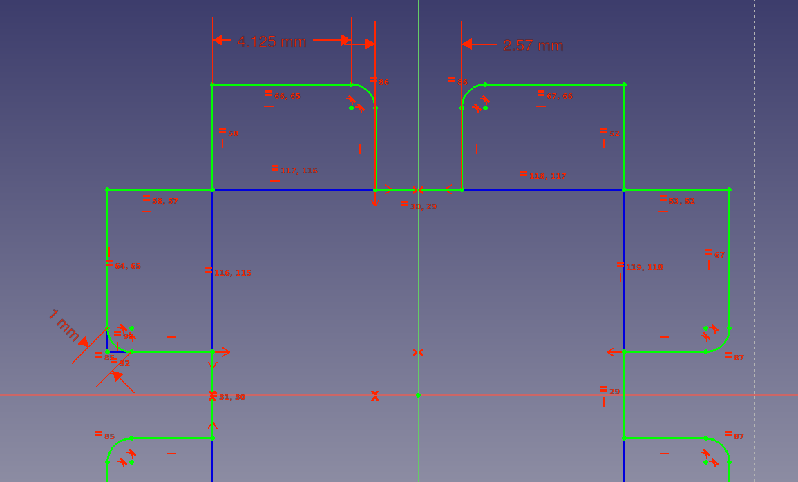
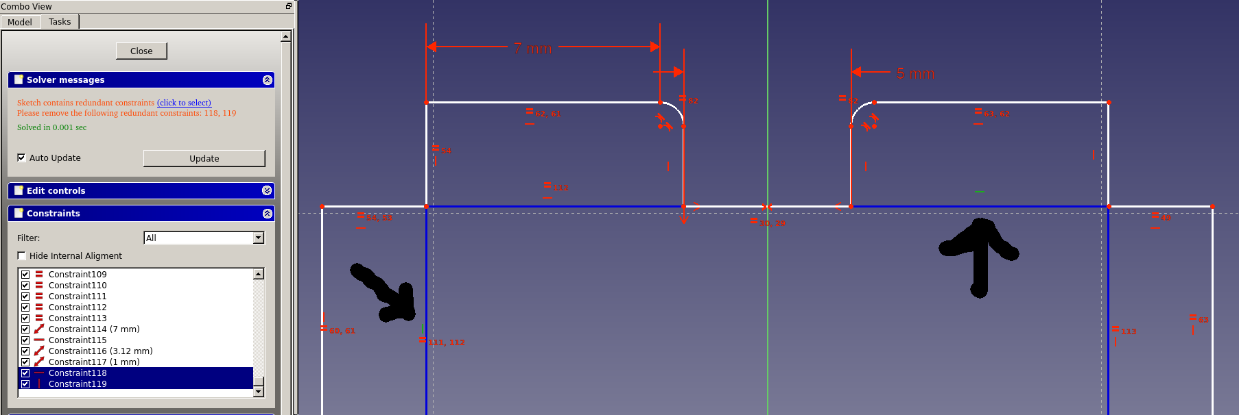
In the “combo view” you have an overview of all the contraints and the status of the sketch (Fully constrained now!)
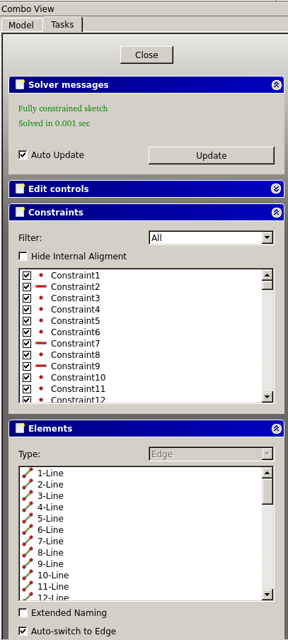
This combo view help you to find the missing contraints in the sketch. It’s a very handy view which i at the end really appreciated!
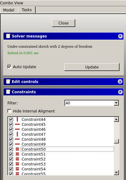
This combo view gives you the errors in the sketch and show you where they are (see the markers). I spend a lot of time playing around with constraints, trying to understand how they relate to each other and what is the best way to get a fully constrained model that is parametric.
Here is the final sketch! Fully constrained.
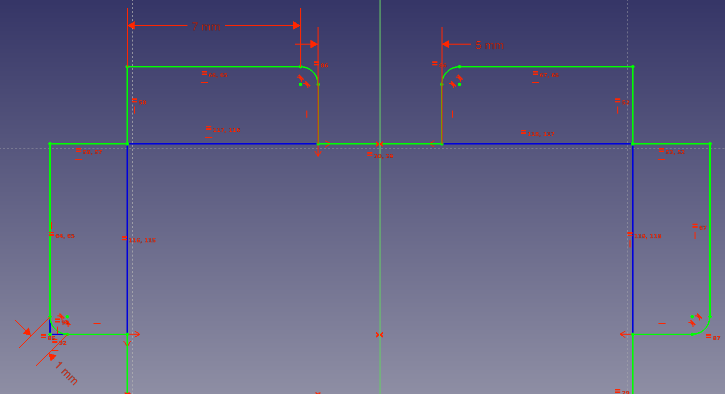
A nice parametric design, that you can controll by changing the 4 parameters! You can do that directly in the combo view.

Because i new the dxf produced by kicad is not read well by the programm we use for the lasercutter is searched for a program to convert the dxf’s to files for the lasercutter. I found qcad as a good intermediar.
On the lasercutter:
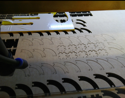
First i did a pressfit measure test with the outcome of the group assignment in mind.
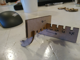
The test measure showed that 2.57mm had the best fit as seen above. So i went back to freecad to adjust the slots.
After implementing the outcome of the pressfit in the parametric design, the lasercutter was setup with the best results we got from the group assignment.
##Lasercutter
Always make sure the ventilation is on until you're done!
In LaserCut5.3, TAB or click out of fields or else the value doesn't stick. :-/
Always engrave before cutting, or else things move.
When you receive the error "read soft-dog error. Please retry." Keep retrying until it works.
If you redo a cut without touching anything but moving the laser head to a new location, check the depth again, because your material might be bowed in the new location.
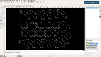
The workflow on the lasercutter:
- open LaserCut5.3
- import the design
- select all and unite lines (screenshot is comming)
- check for double line (with freecad and inkscape i hardly had dxf export with double lines, instead of the others who were using fusion360 and AI).
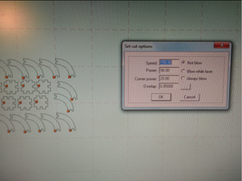
- setup the mode, speed and power according to the test we did in the group assignments
-
select the origen (i always use left-bottom)
- start the lasercutter (turn key and push green button next to it)
- open and place the to be cutted material in the right place
- put the laserhead X and Y axe on the place where you want to have the origin on the material
- use the wooden part to calibrate the z or hight of the head of the laser.
- close the machine
- turn on ventilation
- “download” the file to the laser in LaaserCut5.3 (first delete the remaining file(s)
- push the test button and watch if the design fits on the material
- trun on the laser
- press start
- when done, wait a minute before opening the machine so smoke and dust is sucked out of the machine.
- turn of laser
- turn of ventilation
- shutdown LaserCut5.3
- shutdown the lasercutter.
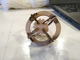
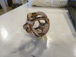
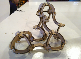
The first run on the lasercutter:
The parts came out like this:
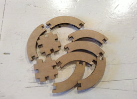
The fit was perfect! Here some samples what you can build with it.