| This week | |
|---|---|
| Presentation electronics production | http://academy.cba.mit.edu/classes/electronics_production/index.html |
| video of the review (computer-controlled cutting) | https://vimeopro.com/academany/fab-2018/video/255840661 |
| video of the lecture | https://vimeopro.com/academany/fab-2018/video/255840870 |
| video of the recitation on fab cities | https://vimeopro.com/academany/fab-2018/video/255496807 |
| Assignment | Used software | Files/Downloads/links |
|---|---|---|
| group assignment | characterize the specifications of your PCB production process | http://fab.academany.org/2018/labs/fablabamsterdam/smallMilling/index.html |
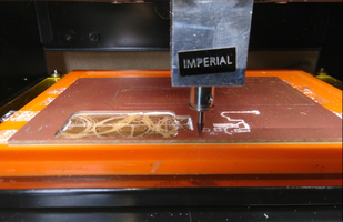
Roland Modela MDX-20
First we did a linetest with this outcome. We were given 2 millingbits, one old and a new one. As seen below you clearly see the difference: the top mill was done with the old bit.
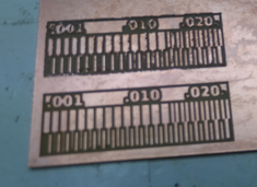
This was a group assignment, for more look at our group assignment page
make an in-circuit programmer by milling the PCB
For the individual assignment this was the documentation for the FabTinyISP.
I started by reading and trying to understand the whole process. And then by downloading the PNG files for milling the board. There are 2 files:
The first is for milling all traces on the copperboard. The second is for cutting out the board and to make through holes if necessary.
First a description of the software: we used the Fab Mods from http://mods.cba.mit.edu/
To get the PCB design into a file the milling machine can read, it has to be converted to paths. I will decribe the steps here:
-1 On the computer (linux OS) connected to the modela, open this url http://mods.cba.mit.edu/ in a webbrowser that handles JS.
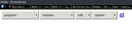
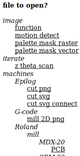
-2 Select on the programs menu the open server programs. This page list a bunch of files to open for several machines common in fablabs. Choose Roland, mill, MDX-20, PCB.
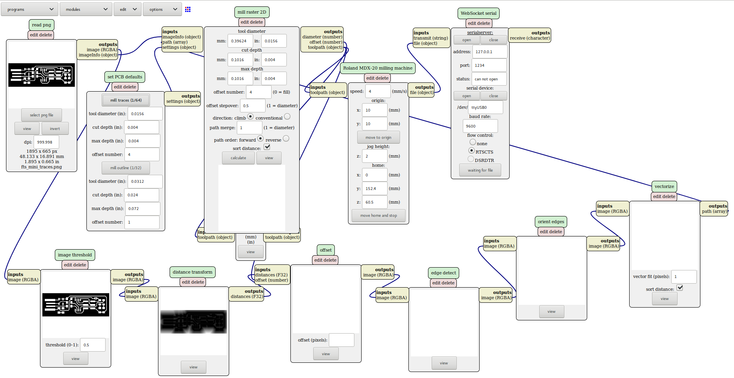
-3 This opens the program used for communicating with the modela. For once a bigger screenschot so you can see the whole thing at once:
-4 Now open the PNG file that has the traces, not the cutlines. In the case of the Brian board, this file is called ft_mini_traces.png.
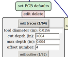
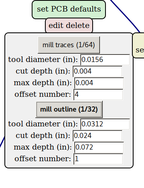
-5 Select mill traces in the Set PCB defaults. After selecting the option will turn bold.
Leave the defaults.
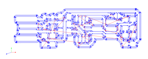
-6 In the next module Mill Raster 2D click on the calculate button and see the images popping up in the 2nd line modules below. This will at the end result in a figure of the traces that are going to be milled.
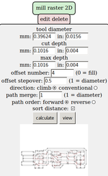
If necessary you can change settings in this modules:
cut dept - layer per trace
max dept - max dept that will be reached
offset 0 will remove all copper
offset stepover - stepover of the lines/traces/diameter milling bit
0.5 is a good default
direction of path
jog height - hight the mill will use to move from one place to another
Path is now calculated, machine is ready to receive.
Check the tab in the browser that opens when you calculate the traces:
-7 On the desktop there is a shortcut to serialserver.sh which starts a deamon to communicate with the modela over usb. Run it in a terminal.
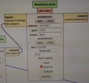
Don’t change settings here. Be sure that there is communication with the modela. You should see message in the status like serial port opened. If that doesn’t work:
- check if the modela is on
- check the cable between computer and modela
- look if the serialserver.sh is still running
- check the WebSocket Serial settings for address (127.0.0.1) and socket (1234) or according to your settings.
-8 Now the software communicates with the modela. It’s time to setup the milling machine.
Prepare the cutting bed, by making sure you have a sacrificial layer. To make sure you get the bed preparation right, take it out of the machine first. Do this by pressing the ‘view’ button on the modela to allow easy access.
Remove all copperboard and tape that’s left on the layer. Evt. use “Sticker remover” to completely clean and clear the layer. You then take a fresh or used copperplate that has enough space for the part you want to create.
Carefully place traces of double sided tape to the sacrificial layer so that a bit more than the copperplate is covered. Don’t let the tape overlap! Turn the bed and by pressing down firmly assure a good grip between the two layers.
Place the bed back into the machine and lock it with the screws.
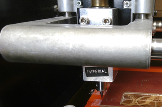
-9 Install the end mill, for the traces you use a 1/64 inch end mill. Unscrew the fastening screw on the head, insert the end mill and tighten. Make sure to put the end mill in as high as you can, but you still can see and grab the point for adjustment later.
-10 Now on the Fab Modules Software fill out values for X and Y and click ‘move to origin’ in the Roland MDX-20 milling machine so the head/spindle moves to the corresponding position. This position is the starting point for your milling work, so choose a place on the material that optimizes this and that will roughly fit your design.
-11 Now that the origin is set, the z-axis needs to be calibrated. You do this on the machine. Move down/up the milling head by pushing the up/down buttons in front of the Modela. Be sure that you keep space between the head rulers and the frame, otherwise you cannot cut deeper as there is space between them. Another thing that’s important is not to push the endmill into the material.
Now go to the origin and unscrew the endmill till it loosens a bit, but keep in in place with your finger, to let it go down in a controlable manner. Put the endmill softly on the copperplate, twist it a few times to avoid dust inbetween mill and plate.
-12 You can now send the calculated traces to the modela. If you can’t, you probably need to calculate again because you changed settings. Or you need to recheck the communication between computer and modela.
-13 Close the cover and send the file!
The actual milling.
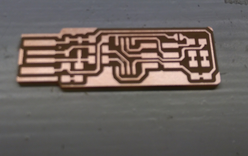
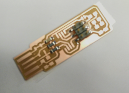
-14 If the traces are milled correctly you will see some dust on the copperplate and it should be clearly visible that there is no more copper where you milled traces.
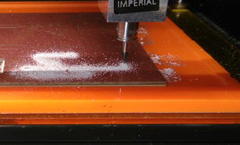
-15 After the job is done remove the dust from the plate.
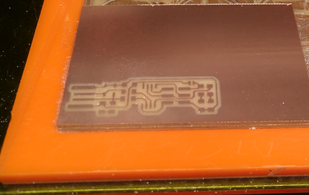
-16 Now you have to cut out the plate. Load the cut outline image and repeat the whole process from point -4. Select Mill outline (1/32) instead of mill traces.
-17 Repeat the whole process till -8 to adjust settings for cutting.
-18 Replace the milling bit by the cutting bit (1/32) and continou the process.
-19 Send the job to the modela and let it cut out the board.
-20 Clean the place, take out the board and wash it with soap and water to get rid of finger grease and dust.
Lessons Learned
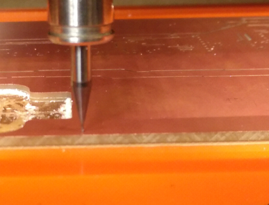
-1 In the group assignment we noticed that the machine was milling correctly on the right side of the board, whereas the left side was only weakly engraved. We concluded that it was due to the copper plate being slightly tilted which caused the differences in cutting depths on both sides.
-2 In the individual assignment while milling the new board of zaerc something similar happened. When i tried the same solution as in the group assignment, namely milling again with a slightly deeper cut dept in the set PCB Defaults, the mill completely ruined the copper.
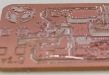
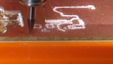
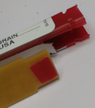
After examining the photos taken during the whole process, I noticed that it wasn’t the copper plate that was slightly tilted, but the tip of the mill was broken. Following photo shows the plate after the first (stopped) run and just before 2nd run. I noticed the missing tip of the mill when zooming in on the photo.
Soldering
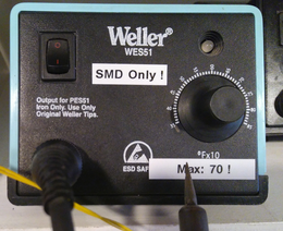
For soldering the SMD components a solderiron is used, in our case a weller station with an iron that has a very small tip.
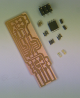
First collect all components that you want to solder on the produced PCB.
Because PCB and SMD components are very small, i used double sided tape and a A4 paper to get more stability. I used a tweezer to old the components in place on the PCB.
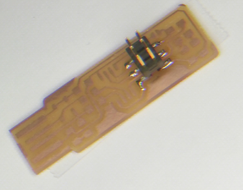
Normally you start soldering the smallest components first. So from the lowest to the highest components. But in this case we first solder the header pins, because of the placement. If you solder the IC first, it’s hard to solder the pins of the headers.
Put a bit solder on one of the islands where you have to put the headers. Then put the headers in place, on top of the just placed solder. Then carefully heat both the leg of the header and the island on the PCB. The solders melts an gravity puts the pins in place. If the legs of the other header pins are touching the right island you can also solder them. At the end you solder the leg where you started (to keep the component in place) again if necessary.
After this is done continue with the other components, starting from small/low components.
When done and all components are soldered on the PCB put some solder on the USB legs and use sandpaper or a file to flatten them in the same hight.
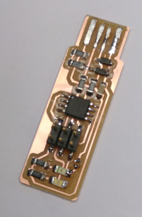
Now the FabTiny is almost ready. Adjust some plastic or paper on the back of the PCB to give a better fit in the USB port of your computer.
After soldering all the components I used a multimeter to check for short circuits, this means using the continuity function and checking if components that should not be connected do touch each other somehow. Look at the design sheet to determine which components should and should not touch, and then using the probes touch these components to check if you hear the beep or not.
Now you are almost ready. To turn this board in a functional programmer the board needs to be programmed.
Programming
I already had all packages installed. Here is the output, because it gives the version number that are install on my machine.
#sudo apt install avrdude gcc-avr avr-libc make

make is already the newest version (4.1-9.1).
avr-libc is already the newest version (1:2.0.0+Atmel3.6.0-1).
avrdude is already the newest version (6.3-4).
gcc-avr is already the newest version (1:5.4.0+Atmel3.6.0-1build1).
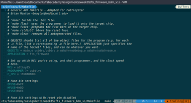
I used VIM as texteditor to edit the Makefile. In the Makefile i changed the MCU (it had attiny45 listed) to attiny85 which we used
MCU = attiny85
I used emma’s programmer to program my board.
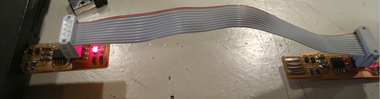
Then i followed the instructions on how to program the board at the bottom of this page to program the board.
The output of the command is listed below.
#make

avr-gcc -mmcu=attiny85 -Wall -DF_CPU=16500000UL -I. -funsigned-char -funsigned-bitfields -fpack-struct -fshort-enums -Os -Iusbdrv -c main.c -o main.o
main.c:109:13: warning: always_inline function might not be inlinable [-Wattributes]
 static void delay ( void )
             ^
avr-gcc -mmcu=attiny85 -Wall -DF_CPU=16500000UL -I. -funsigned-char -funsigned-bitfields -fpack-struct -fshort-enums -Os -Iusbdrv -c usbdrv/usbdrv.c -o usbdrv/usbdrv.o
avr-gcc -mmcu=attiny85 -Wall -DF_CPU=16500000UL -I. -funsigned-char -funsigned-bitfields -fpack-struct -fshort-enums -Os -Iusbdrv -c usbdrv/oddebug.c -o usbdrv/oddebug.o
avr-gcc -x assembler-with-cpp -mmcu=attiny85 -Wall -DF_CPU=16500000UL -I. -funsigned-char -funsigned-bitfields -fpack-struct -fshort-enums -Os -Iusbdrv -c usbdrv/usbdrvasm.S -o usbdrv/usbdrvasm.o
avr-gcc -mmcu=attiny85 -o fts_firmware.elf main.o usbdrv/usbdrv.o usbdrv/oddebug.o usbdrv/usbdrvasm.o
avr-size -C --mcu=attiny85 fts_firmware.elf
AVR Memory Usage
----------------
Device: attiny85

Program:    2470 bytes (30.2% Full)
(.text + .data + .bootloader)

Data:         75 bytes (14.6% Full)
(.data + .bss + .noinit)


avr-objcopy -j .text -j .data -O ihex fts_firmware.elf fts_firmware.hex
#make flash
avrdude -p attiny85 -c usbtiny -P usb -e \
	-U flash:w:fts_firmware.hex

avrdude: AVR device initialized and ready to accept instructions

Reading | ################################################## | 100% 0.00s

avrdude: Device signature = 0x1e930b (probably t85)
avrdude: erasing chip
avrdude: reading input file "fts_firmware.hex"
avrdude: input file fts_firmware.hex auto detected as Intel Hex
avrdude: writing flash (2470 bytes):

Writing | ################################################## | 100% 3.08s

avrdude: 2470 bytes of flash written
avrdude: verifying flash memory against fts_firmware.hex:
avrdude: load data flash data from input file fts_firmware.hex:
avrdude: input file fts_firmware.hex auto detected as Intel Hex
avrdude: input file fts_firmware.hex contains 2470 bytes
avrdude: reading on-chip flash data:

Reading | ################################################## | 100% 6.00s

avrdude: verifying ...
avrdude: 2470 bytes of flash verified

avrdude: safemode: Fuses OK (E:FF, H:DD, L:E1)

avrdude done.  Thank you.
#make fuses

avrdude -p attiny85 -c usbtiny -P usb \
	-U lfuse:w:0xE1:m -U hfuse:w:0xDD:m \
	-U efuse:w:0xFF:m

avrdude: AVR device initialized and ready to accept instructions

Reading | ################################################## | 100% 0.00s

avrdude: Device signature = 0x1e930b (probably t85)
avrdude: reading input file "0xE1"
avrdude: writing lfuse (1 bytes):

Writing | ################################################## | 100% 0.00s

avrdude: 1 bytes of lfuse written
avrdude: verifying lfuse memory against 0xE1:
avrdude: load data lfuse data from input file 0xE1:
avrdude: input file 0xE1 contains 1 bytes
avrdude: reading on-chip lfuse data:

Reading | ################################################## | 100% 0.00s

avrdude: verifying ...
avrdude: 1 bytes of lfuse verified
avrdude: reading input file "0xDD"
avrdude: writing hfuse (1 bytes):

Writing | ################################################## | 100% 0.00s

avrdude: 1 bytes of hfuse written
avrdude: verifying hfuse memory against 0xDD:
avrdude: load data hfuse data from input file 0xDD:
avrdude: input file 0xDD contains 1 bytes
avrdude: reading on-chip hfuse data:

Reading | ################################################## | 100% 0.00s

avrdude: verifying ...
avrdude: 1 bytes of hfuse verified
avrdude: reading input file "0xFF"
avrdude: writing efuse (1 bytes):

Writing | ################################################## | 100% 0.00s

avrdude: 1 bytes of efuse written
avrdude: verifying efuse memory against 0xFF:
avrdude: load data efuse data from input file 0xFF:
avrdude: input file 0xFF contains 1 bytes
avrdude: reading on-chip efuse data:

Reading | ################################################## | 100% 0.00s

avrdude: verifying ...
avrdude: 1 bytes of efuse verified

avrdude: safemode: Fuses OK (E:FF, H:DD, L:E1)

avrdude done.  Thank you.
#make rstdisbl
avrdude -p attiny85 -c usbtiny -P usb \
	-U lfuse:w:0xE1:m -U hfuse:w:0x5D:m \
	-U efuse:w:0xFF:m

avrdude: AVR device initialized and ready to accept instructions

Reading | ################################################## | 100% 0.00s

avrdude: Device signature = 0x1e930b (probably t85)
avrdude: reading input file "0xE1"
avrdude: writing lfuse (1 bytes):

Writing | ################################################## | 100% 0.00s

avrdude: 1 bytes of lfuse written
avrdude: verifying lfuse memory against 0xE1:
avrdude: load data lfuse data from input file 0xE1:
avrdude: input file 0xE1 contains 1 bytes
avrdude: reading on-chip lfuse data:

Reading | ################################################## | 100% 0.00s

avrdude: verifying ...
avrdude: 1 bytes of lfuse verified
avrdude: reading input file "0x5D"
avrdude: writing hfuse (1 bytes):

Writing | ################################################## | 100% 0.01s

avrdude: 1 bytes of hfuse written
avrdude: verifying hfuse memory against 0x5D:
avrdude: load data hfuse data from input file 0x5D:
avrdude: input file 0x5D contains 1 bytes
avrdude: reading on-chip hfuse data:

Reading | ################################################## | 100% 0.00s

avrdude: verifying ...
avrdude: 1 bytes of hfuse verified
avrdude: reading input file "0xFF"
avrdude: writing efuse (1 bytes):

Writing | ################################################## | 100% 0.00s

avrdude: 1 bytes of efuse written
avrdude: verifying efuse memory against 0xFF:
avrdude: load data efuse data from input file 0xFF:
avrdude: input file 0xFF contains 1 bytes
avrdude: reading on-chip efuse data:

Reading | ################################################## | 100% 0.00s

avrdude: verifying ...
avrdude: 1 bytes of efuse verified

avrdude: safemode: Fuses OK (E:FF, H:5D, L:E1)

avrdude done.  Thank you.
dmesg -t

    usb 1-1: new low-speed USB device number 20 using xhci_hcd
    usb 1-1: New USB device found, idVendor=1781, idProduct=0c9f
    usb 1-1: New USB device strings: Mfr=0, Product=2, SerialNumber=0
    usb 1-1: Product: USBtinySPI
#lsusb
...
Bus 001 Device 021: ID 1781:0c9f Multiple Vendors USBtinySPI
...