| This week | |
|---|---|
| Presentation Input Devices | http://academy.cba.mit.edu/classes/input_devices/index.html |
| Video of the review (molding and casting) | http://fab.academany.org/2018/lectures/fab-20180404.html |
| video of the lecture | http://fab.academany.org/2018/lectures/fab-20180404.html |
| recitation: circular innovation challenge (Eric King) | http://fab.academany.org/2018/lectures/fab-20180409.html |
| Assignment | Used software | Files/Downloads/links |
|---|---|---|
| Group Assignment | measure the analog levels and digital signals in an input device | http://fab.academany.org/2018/labs/fablabamsterdam/inputdevices/index.html |
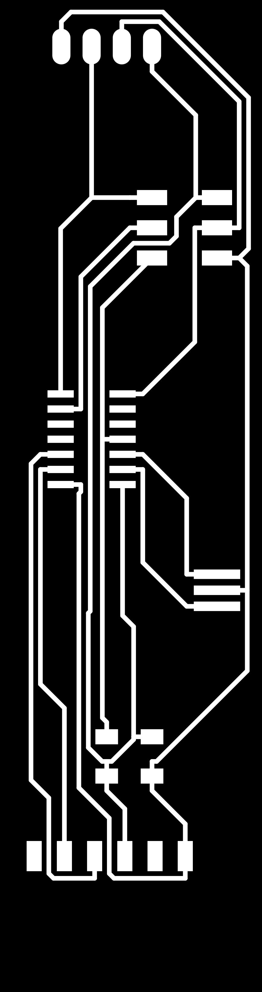
| pcb hc-sr04 | kicad | kicad4-hc-sr04.zip |
| code | arduino | hc-sr04.ino |
| png traces milling | kicad/gimp | basic_board-F.Cu.png |
| png cut milling | kicad/gimp | basic_board-Margin.png |
Research
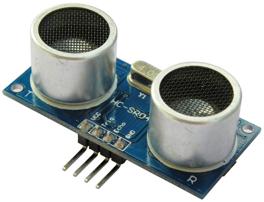
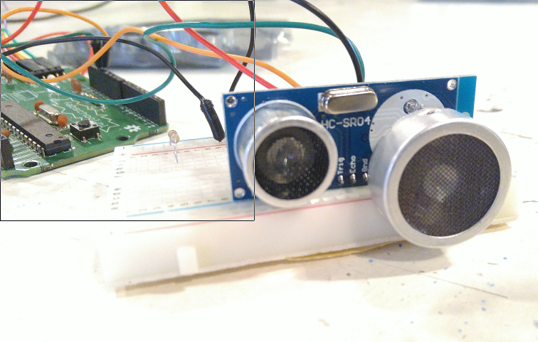
I wanted to do some work for my final project, which is measuring ice thickness. For that i hope to use a ultrasonic sensor, namely the HC-SR04. This sensor i’ve used a lot in the fabschool project. It’s a wonderfull sensor, specially with kids. You don’t see or hear what it’s doing, but with the output you can measure distance. More or less like bat’s navigate.
But now i really wanted to get a deeper understanding how it functions, because i think i will use it to measure ice.
https://hackaday.com/2014/03/17/good-vibrations-giving-the-hc-sr04-a-brain-transplant/
This article was the start of a nice journey into understanding the HC-SR04. It leads to the following link, a page mentioned on hackaday as the source of the article:
http://uglyduck.ath.cx/ep/archive/2014/01/Making_a_better_HC_SR04_Echo_Locator.html
The circuit has 2 transducers one for emission and one for reception. To transmit the ultrasonic pulses a relatively high voltage is needed. A MAX232 (U3) is cleverly used to produce +/-10V (which are the normal USART voltages) from 5V. The transducer is connected between two outputs so it is in fact powered at 20V. Power is only applied to this circuit through Q2 some time before and during pulse emission because the internal switching charge-pump is noisy. When the circuit switches to receive mode the MAX232 power is cut off. The receive and emit circuits are controlled by an EM78P153S chinese microcontroller running at 27MHz. The receiver side uses LM324 which contains 4 OPAMPs. U2D is just a times 6 amplifier. U2C is a multiple feedback (1st order) pass band filter which is followed by another times 8 amplifier (U2B). The last OPAMP (U2A) is used together with Q1 as a hysteresis comparator. I’ve simulated the filter in PSpice and it is not centered at 40KHz as it should be but instead it has a 18KHz peak. By changing just two resistors (R13 to 2K2 and R11 to 18K) the filter response is shifted to the pulse frequency and this greatly improves the detection sensitivity.
Here is the schematic of the HC-SR04 from his page:
The bunch of HC-SR04 sensors that we have at the Waag have a slightly other layout. But with the schematic and some guessing the board acts the same as this reversed engineered board.
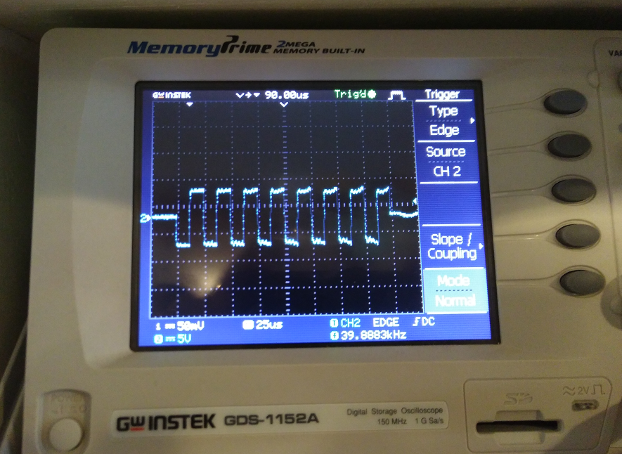
The page also mentioned another site with information which contains the most beautifull output from an oscilloscope, of how the sensor actually works:
! 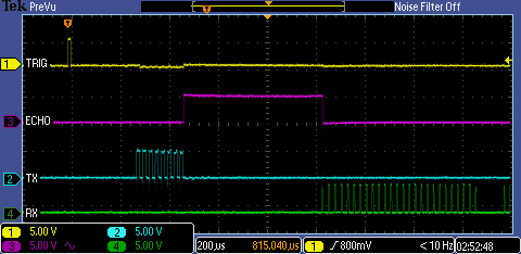
The first yellow line is the TRIG pin. Normally you pulse this pin to get the sensor started.
Then the blue line is the TX for sending the ultrasonic pulses to the sending transducer. As you can see it send 8 short pulses.
After the 8 pulses are send, the ECHO pin (Magenta) is set to HIGH and turns LOW once the RX (GREEN line), the receiving transducer gets the first echo back. The time the ECHO pin was high divided by 2 times / 29.1 is the distance to the object (see the code example).
I tried to measure it myself. These are the 8 pulses the TX sends:
Here you see the TX on the orange line (8 short pulses seen as 1 pulse) and then the RX in blue turning low is the receiving echo. Unfortunately i missed an image of the same with an object further away.
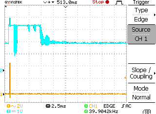
The measuring was a bit hard, because i didn’t see any signal (only noise) on the RX, so i measured at the last lm324 (see schematic above). Only after the signal went though 4 amps provided on the board, i discovered the receiving pulses.
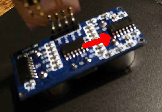
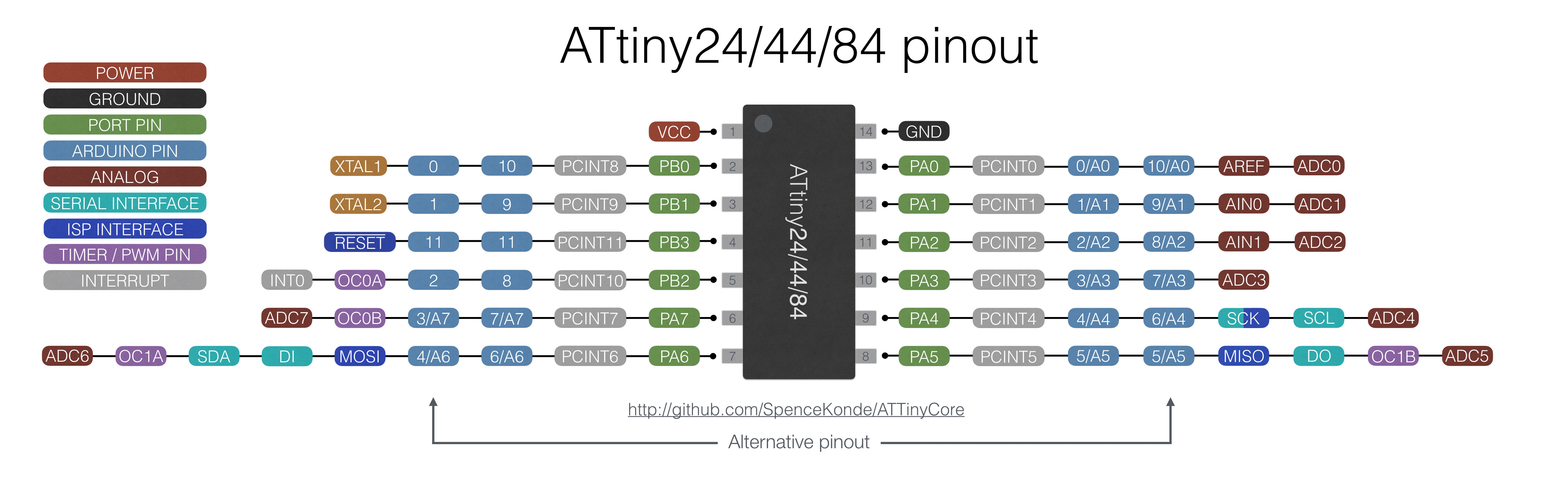
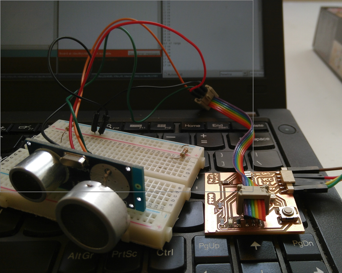
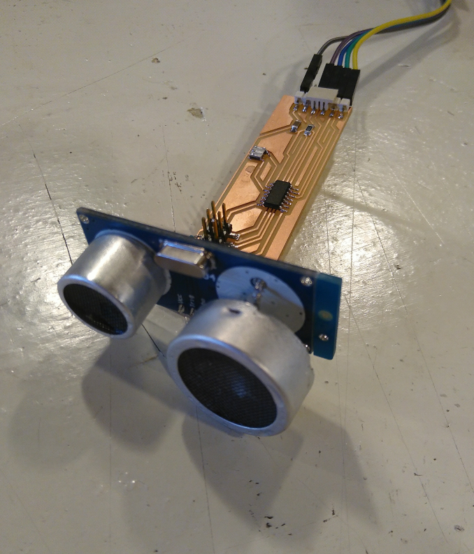
Board
I made this basic board to connect the hc-sr04 module:
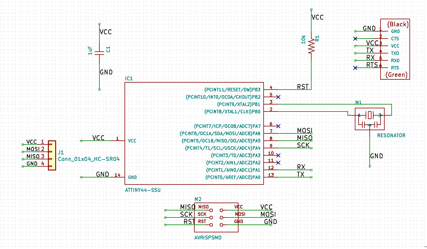
It’s a basic attiny84 board, based on the hello world board I made during the electronics design week. I removed the button, the Phototransistor and the led from the hello world board schematics. Then added a 4 pins smd connector for the hc-sr04 module.
The bootloader was burned with the ISP - in-circuit programmer made during the electronics production week. The board uses the external 20mhz of the resonator as clock.
The hc-sr04 needs of course VCC and GND.
- for the HC-SR04 i connected these pins:
- Trigger pin = MOSI/PA6
- Echo pin = MISO/PA5

- for the softserial communication:
- TX = PA0
- RX = PA1

- for the resonator
- PB0 / XTAL 2
- PB1 / XTAL 2
Code
The code i wrote is compact and clean!
First i included the softwareserial.h to send the outcome of the measurements to the ftdi’s tx and rx, so i get realime measurements in the console (seen by using this command in a terminal “screen /dev/ttyUSB0 9600”).
Then i defined the pins according to the schematics of my board.
In the setup function the serial baudrate is set, followed by the pinmode of the defined pins.
The loop i first used the “long” variable for using a value of any type.
The next 4 lines pulses the trigger pin of the hc-sr04. For how the hc-sr04 module actually works see the serearch i did on top of this page.
Then the calculation is done by reading the echoPin. I calculates the distance by getting the duration between the pulse signal and the echo of the echoPin, dividing it by 2 (/2 because the signal travels to the object and back) and then divided by the speed of sound the (/29.1).
Then it uses the distance for outputting to serial (TX). If the distance is more than 400 or less then 0, print “out of range”, otherwise print the distance to serial.
Explaining the code costed more time than writing it :)
#include <SoftwareSerial.h>
#define rxPin 0
#define txPin 1
#define trigPin 6
#define echoPin 5

SoftwareSerial serial(rxPin, txPin);

void setup() { //
  serial.begin (9600);
  pinMode(rxPin, INPUT);
  pinMode(txPin, OUTPUT);
  pinMode(trigPin, OUTPUT);
  pinMode(echoPin, INPUT);
}

void loop() {
  long duration, distance;
  digitalWrite(trigPin, LOW);
  delayMicroseconds(2);
  digitalWrite(trigPin, HIGH);
  delayMicroseconds(10);
  duration = pulseIn(echoPin, HIGH);
  distance = (duration/2) / 29.1;

  if (distance >= 400 || distance <= 0){
    serial.println("Out of range");
  }
  else {
    serial.print(distance);
    serial.println(" cm");
  }
  delay(500);
} /* */
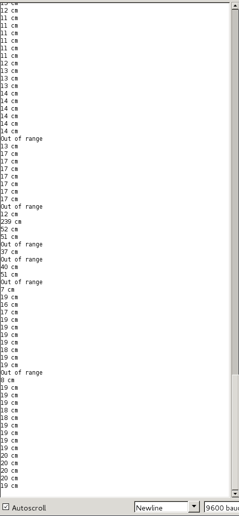
It works on ice, but…
It works with ice, of a thickness of about 5 cm. Al lot of pulses get lost (out of range). Thickness should be about 4 cm, but ranges between 4-10. Time traveling of sound trough ice is about twice as long as air, so the major clear signal of 7cm i(ice thickness of 3.5cm) should be more or less ok.
4 cm
4 cm
10 cm
4 cm
4 cm
3 cm
Out of range
4 cm
Out of range
5 cm
9 cm
8 cm
7 cm
7 cm
7 cm
7 cm
6 cm
7 cm
7 cm
7 cm
7 cm
7 cm
7 cm
7 cm
302 cm
Out of range
Out of range
10 cm
Out of range
15 cm
Out of range
16 cm
Out of range
15 cm
7 cm
Out of range
6 cm
Out of range
12 cm
Out of range
11 cm
Out of range
12 cm
Other measurement tests and modifications i did:
Measuring distance to water. Works :)
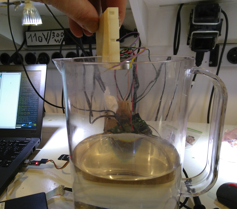
Measuring ice on water. Works… till about 5 cm thickness.
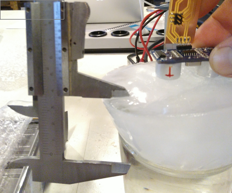
I then modified the hc-sr04. I had a bigger 40khz transducer that i used to replace the RX to get a better echo. The transducer is a efr-rcb40k54
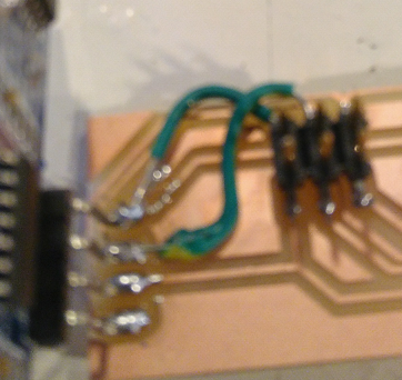
Did some measurements and finally replaced it with the hc-sr04 that’s on my newly made board, damaging the lanes on the pcb. I used 2 wires to make bypasses.
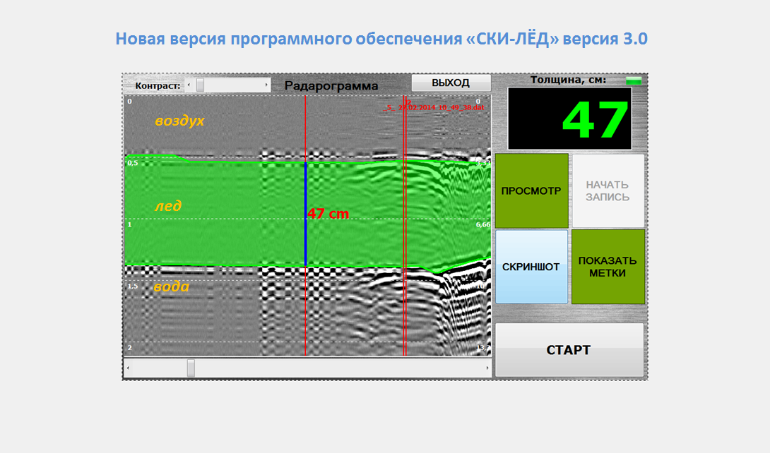
Does it work for my final project? NO!
during searching for possibilities i found these tehcnics (ultra-wideband impulse radar). With this technic you get good results (see the russian video), but a bit out of range for the fabacademy :(
https://hackaday.com/2013/10/05/homebuilt-ultra-wideband-impulse-radar/
http://glcharvat.com/shortrange/
http://glcharvat.com/Dr._Gregory_L._Charvat_Projects/XbandUWBImpulseRadar.html

http://uwbs.ru/products/izmeritel-tolschiny-lda-picor-ice/?lang=en