| This week | |
|---|---|
| Presentation machine design | http://academy.cba.mit.edu/classes/machine_design/index.html |
| video of the review (mechanical design) | http://fab.academany.org/2018/lectures/fab-20180509.html |
| video of the lecture | http://fab.academany.org/2018/lectures/fab-20180509.html |
| video of the recitation making things that matter | http://fab.academany.org/2018/lectures/fab-20180514.html |
| Assignment | Used software | Files/Downloads/links |
|---|---|---|
| Group Assignment | actuate and automate your machine and document the group project and your individual contribution | http://archive.fabacademy.org/2018/labs/fablabamsterdam/students/henk-buursen/group.html |
| code for the machine | arduino-ide | machine.ino |
| tube extractor test code | arduino-ide | test-code.ino |
- The Random Dutch Lunch Generator
arduino, cnc-shield and pins/functions
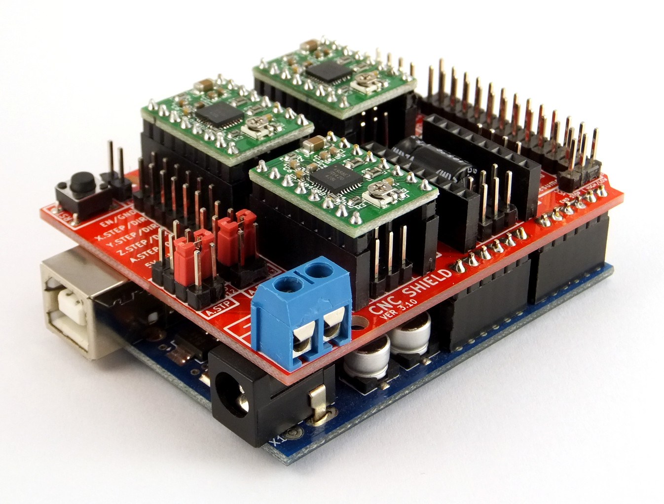
For the machine we use 3 “DRV8825 Stepper Motor Driver Carrier, High Current” shield to drive the stepper motors. They are attached to the Protoneer Arduino CNC Shield. This CNC-shield fits on a arduino uno.
The programming is done on the arduino, so to understand what pin is needed for the project, we used these 3 images to get an overview. The first on is the scheme of the cnc shield. The shield we started with already had 3 DRV8825 shields on top. We used position X, Y and Z. The A position was not used. On the right sight of the shield were the connectors (4pins) to plugin the wires for the 3 steppermotors. Under each DRV8825 shield are 6 pins positions named MO, M1 and M2. We connected them all with jumpers to get 1/32 microsteps per step (so 200*32=6400) for a complete revolution. Our stepper has 200 steps per revolution. I didn’t mention that before :)
| MODE0 | MODE1 | MODE2 | Microstep Resolution |
|---|---|---|---|
| Low | Low | Low | Full step |
| High | Low | Low | Half step |
| Low | High | Low | 1/4 step |
| High | High | Low | 1/8 step |
| Low | Low | High | 1/16 step |
| High | Low | High | 1/32 step |
| Low | High | High | 1/32 step |
| High | High | High | 1/32 step |
Another pin we used was the enable pin, to activate the motors, which is probably the E-Stop location on the scheme.
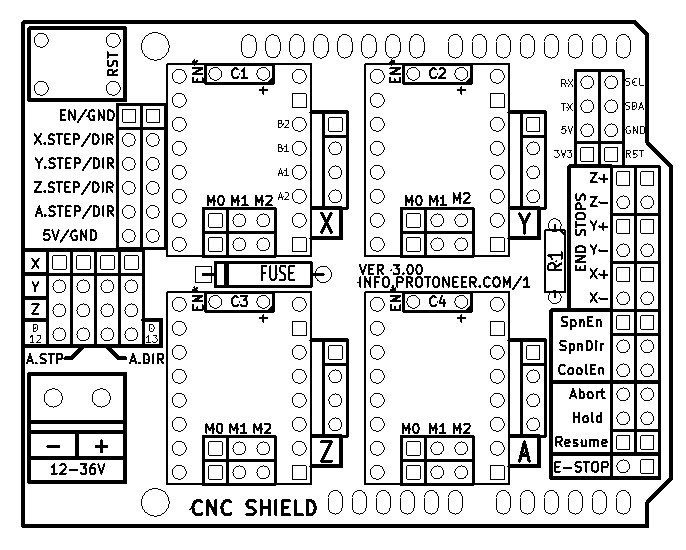
By reading the next image we could figure out what pins were connected. Digital 2-13 are all connected to the CNC shield. But, in our case, we only used D2-8. The analoge pins A0-A3 are also connected and used. Pin A4 and A5 are not used.
We were looking how to connect the button, to get a topping on you sandwich, and the 2 servos we needed for the funnels.
For the button it was quite easy. We used pin A5, because it was free.
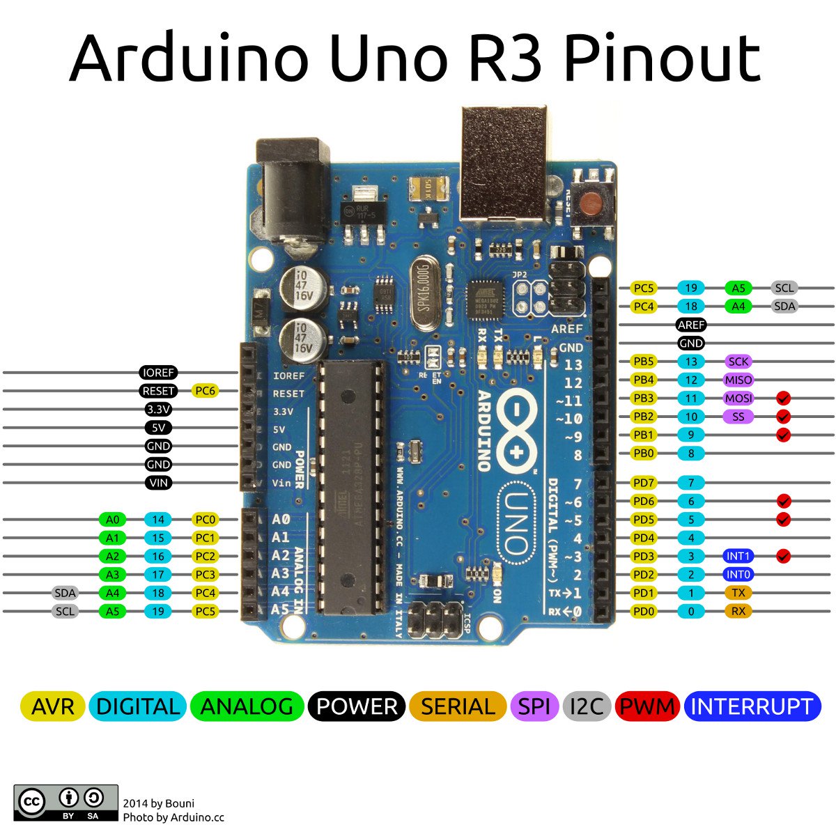
To connect the 2 servos was more complicated because we thought that these servos needed to be connected to PINs with PWM functionality. From the arduino pinout below we knew that PWM is only available on pin D3, D4, D5 and D9, D10, D11. So the only pins we could use for the servos are D9 and D10 (and D11 also).

Tube extractor test
The test code
#define EN        8      //Negative Enable pin
#define X_DIR     5      //Direction pin
#define X_STP     2     //Step pin

int delayTime=80; //Delay between each pause (uS)
int stps=6400;// Steps to move microsteps 1/32 (200*32 = 6400)
void step(boolean dir, byte dirPin, byte stepperPin, int steps) {

  digitalWrite(dirPin, dir); //

  for (int i = 0; i < steps; i++) {
    digitalWrite(stepperPin, HIGH);
    delayMicroseconds(delayTime);
    digitalWrite(stepperPin, LOW);
    delayMicroseconds(delayTime);
  }
}
void setup(){
  pinMode(X_DIR, OUTPUT); //direction pin = output
  pinMode(X_STP, OUTPUT); //step pin = output
  pinMode(EN, OUTPUT); //negative enable pin  =output
  digitalWrite(EN, LOW); //start negative enable pin at low
}
void loop(){
	step(true, X_DIR, X_STP, 3200); //true equals back towards motor
 	delay(2000);

 }
I wrote this script to test the tube extractor. And it’s working.
I connected the steppermotor to the X-position of the DRV8825 shield on the CNC shield. I put together this code:
 - defining all connections to the X_DIR- and STP (and don't forgot the negative ENABLE pin).
 - copied the code for the motor settings
 - setup function for the pinmodes

 loop:
 - do a half revolution and then rest for 2 seconds.
go to the beginning of this page for a full description of the shields and pins or continou reading from here as in the next chapture i explain the code we used for the machine.
But first an impression of the working test code and the tube extractor:
the arduino code for our machine
Goals this week
Till now i only copied programms, removed bits i didn’t need and declared the pin numbers i used. So this was my first proper programm. I didn’t use the functions till now. Everything fitted in the setup or loop. So this week i learned a bit how to use them. A thing i liked is that it gives a better overview of the code, separating complexities in functions. Other things i used before but didn’t really understand where the “#declare”, “for” and “int”, so the “values (variables and constants)”.
In this explained of the code we wrote, i try to explain what i think they all do.
the code explained
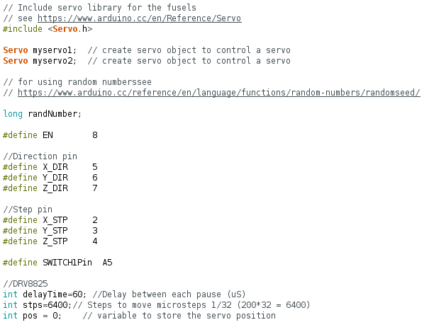
Includes and Variables
The beginning of the code starts with a couple of includes and variables.
The first block handles the include of a servo library and the variables of the 2 servos we use for the funnels. If you want to know more read the page of the servo library. We called the 2 servos myservo1 and myservo2.
Then follows a line that has to do with the random nummers we use for the stages. Long variables are extended size variables for number storage.
Pins for working with the cnc-shield are declared in the next block, followed by the pinnumber for the button. At this section on shields and pins you can see the schematics and explanation of the pins that we use in this code.
Last in this block are variables for the steppermotors. A revolution of the stepper consists of 200 steps. With the DelayTime you give the amount of delay after 1 step. So the higher the delay, the longer a revolution will last, in other words: the less delay the higher the speed of a revolution. STPS handles the microsteps per step. On the CNC-shield we used jumpers to set it to 1/32 microsteps per step. So a complete revolution (stps) will be 200*32=6400 microsteps.
Going through the arduino references i noticed this description of #define. Next program i’m gonna try to use const….
#define is a useful C component that allows the programmer to give a name to a constant value before the program is compiled. Defined constants in arduino don’t take up any program memory space on the chip. The compiler will replace references to these constants with the defined value at compile time.

This can have some unwanted side effects though, if for example, a constant name that had been #defined is included in some other constant or variable name. In that case the text would be replaced by the #defined number (or text).

In general, the const keyword is preferred for defining constants and should be used instead of #define.
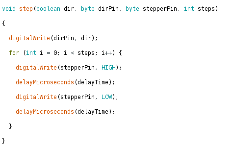
For the void-step():
To be honest we copied the first function from a arduino code we got from Emma. It handles the way how it will write LOW and HIGH according to the (micro-)steps and timedelay between the steps we handled in the first block. Anyway: it’s doing what it supposed to do :)
I will emma ask later on for an explanation.
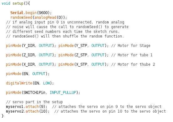
For the void-setup():
The setup() function is called when a sketch starts. Use it to initialize variables, pin modes, start using libraries, etc. The setup() function will only run once, after each powerup or reset of the Arduino board.
For debugging serial is enabled.
Next comes a line to activate the randomseed(). Arduino reference for randomseed.
If it is important for a sequence of values generated by random() to differ, on subsequent executions of a sketch, use randomSeed() to initialize the random number generator with a fairly random input, such as analogRead() on an unconnected pin.
We used pin A0 for this, because it’s not used in our sketch.
After that we set the modes for the different pins. For the stepper it are all OUTPUTS, only for the button we used the pin as INPUT_PULLUP, meaning this pin is HIGH and when pushed puts the pin in a LOW state.
Last the servo pin are declared in the setup (pin D9 and D10), see this section on shields and pins.
The void loop() is pretty clean. Put in word:
- when the button is pushed, start to pick a random number.
- if the number equals N, goto stage/library N
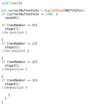
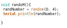
The void randoM() is the function that picks a random number between 0-4. So random numbers are 1, 2 and 3.
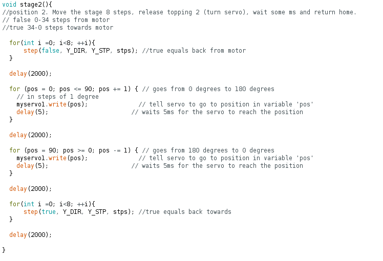
The last functions are the 3 stages/positions.
First it activates motor Y connected to the stage. With a “for” statement it uses steps to go to the right position. In this case it does <8 steps, so it counts from 0 till <8 which is 7, in total 8 steps.
When it is in position is delays for 2000ms.
On top of this position hangs a funnel driven by the first servo. The servo opens the funnel by going from position 0 to 90 in 90 steps delayed by 5ms. This opens the funnel.
This open funnel is delayed by 2000ms, the hagelslag/chocolate prinkles are falling down.
Now the servo closes the funnel by doing the opposite as above.
The funnel is now closed again and delays again to catch also the latest fallen hagelslag/chocolate prinkles.
Now the stepper motor Y is going back home, same as above, but in thee opposite direction.
When home, 2000ms delay, before it goes again in the loop function, starting over the whole process.
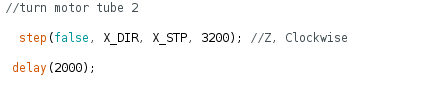
The other stages are activating the other servo (position 3) and another stepper that is emptying the tube (position 4).
The code used for the tube only does a half revolution, that should be enough for the ketjup to be pushed out.
what was learned
A lot! Trying to read code is different than really understand code! Till now i was able to read code and fiddle a bit around with it. I now have a better understanding of the code.
What could have been improved
As said in the mechanical design week there were probably better options for extruding ketchup from the tube. Furter improvements could have been:
- get more toppings at once, so push tree times and get 3 random toppings.
- speeding up the stage travel. Easy to implement: decrease the delayTime between the steps of the stepper.
- implement random speed travel to the stages. The machine takes a lot of time to travel to and from the stages. By randomizing the speed it would have been a bit more attracktive to look at.