Week 11: Input Devices
This weeks assignment:
- measure something: add a sensor to a microcontroller board that you have designed and read it
Planning for my final project
For my final project I want to experiment with stretch sensors. I searched the FabAcademy Archive and found the portfolio of Citlali. I have gratefully used her work to design my own board. She mentions Lilypad components that she got from the Lilipad library. It comes from the Lilypad Arduino that was designed and developed by Leah Buechley and SparkFun Electronics. They are pads that you can attach fabric stretch sensors to, like the ones you find at the KOBAKANT website. This is a type of stretch sensor I would like to use. Also I would like to be able to combine two stretch sensor signals. So the plan is to make a input board with pads to connect two stretch sensors to. As the stretch sensor needs a pull up resistor, but it is unknown what value it should have, I will add two double female headers to be able to try out different resistors.
Designing the board in EAGLE
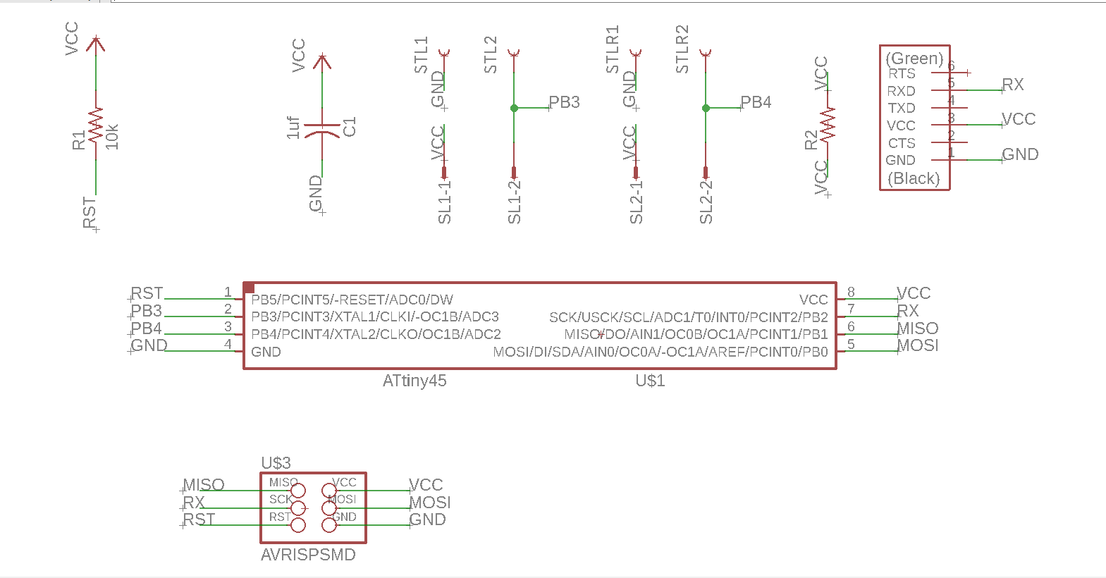
This is the list of compartments on my board:
- attiny45
- capacitator 1uf
- resistor 10k Ohm
- 6 pin header (AVRISPSMD)
- FTDI header
- 2 SEWTAP_LONG, from the library of Lilypad Wearables
- 2 SEWTAP_LONG_ROUND, from the library of Lilypad Wearables
- 2 AMP QUICK CONNECTORS, from the library of con-amp-quick
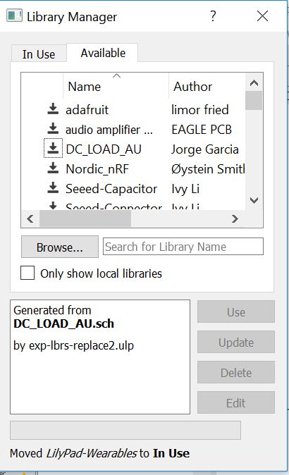
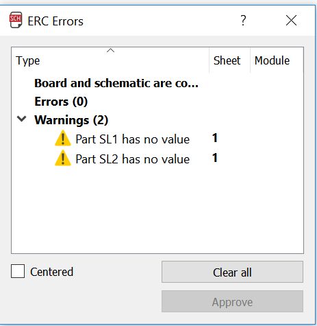
To add the Lilypad libary, under Library in the toolbar, I clicked 'Open library manager'. Under the tab 'Available' I searched for Lilypad Wearables and moved the library to 'In use'. After I added all the components and made all the connections in the schematic view, I ran an ERC to check if all the lectronic rules were applied. Eagle gave me the warning that Part SL1 and SL2 have no value. I ignored that, because the value is indeed unknown untill I put in a resistor there.
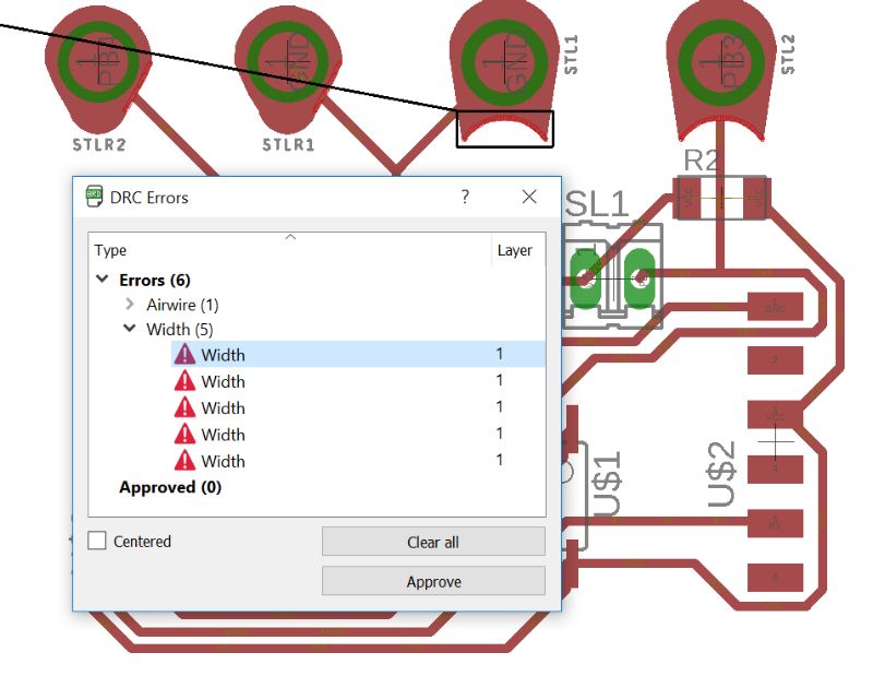
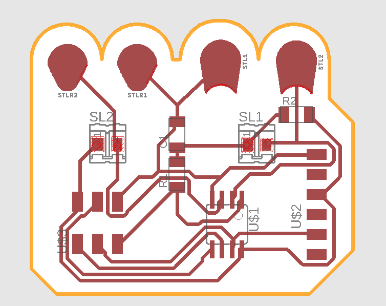
After this I created a board view and put all the components in the right place. I used the autorouter and it actually gave me a few 100% matches. But since I wanted no traces around the lily pads, I used a design that had only one trace around two of the pads and used a 0 Ohm resistor to lead that trace underneath the pads. Also I needed actual surface mount pads for my quick amp connectors. So in the top layer I drew rectangles over the the STL1 and STL2 pads. When I ran the DRC check, it gave me some errors. Few of then had to to with too little space between traces. I fixed that. One was an airwire on the 0 Ohm resitor. That made sense, because I had connected both ends to VCC because it is only a bridge. The last was about the width of the lilypads. That I ignored as well. The lilypads are great, do not touch the lily pads.
After I was satisfied with my board and Emma checked it, it was time to make PNG files. I made the mistake of leaving one line in the 51 tdocu layer that made the board twice as big. From Johanna I learned that you can actually draw lines and arcs in the layer of your choosing. This way I could draw the outlines of the board nicely around the lily pads. When I generated the PNG files, I opened them in GIMP and inverted the colors by clicking 'color' in the toolbar and then 'Value Invert'. Here you can find my eagle and .PNG files.
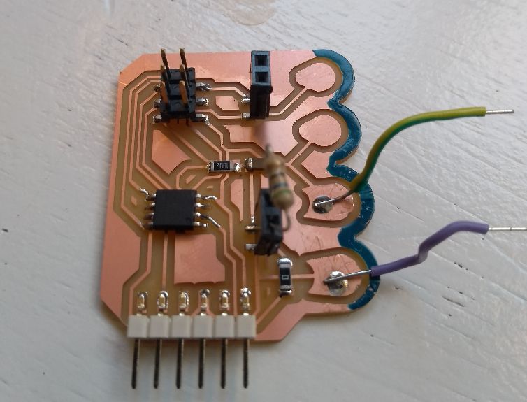
Engraving, cutting, soldering
Now I was ready to engrave and cut with the Modella. I did as I did in week 5. After that I soldered on all the components. To be able to fit the female headers I made on my board, I cut them with what in Dutch is called a moniertang
. That worked really well.Programming the board
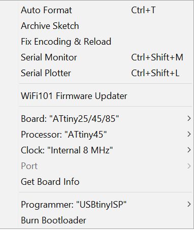
To program the board I can use the programmer I used in week 5. In the Arduino programming software I changed some settings. From the datasheet I read that the internal clock of the attiny is at 8Mhz. After I selected the right microcontroller and the clicked 'burn bootloader'. I got the message that it was succesfull.
Testing the stretch sensor
First I measured the resistance of the stretch sensor with a multimeter. Check the first video above. From Citlali's webpage I saw that she had the multimeter on 300 Ohm. I have an option for 200 or 2K. I put the multimeter on 2K Ohm. In rest I measure a resistance of around .14, that is 140 Ohm. Fully stretched, I measured .015, that is 15 Ohm. I checked it again putting the multimeter on 200 Ohm. Now I measured a rest-resistance between 135 and 136 Ohm and a stretch resistance between 15 and 16 Ohm. This means the pull up resistor should be an average of that; around 75 Ohm. At the lab we have 56, 68 and 82 Ohm. I will experiment with those.
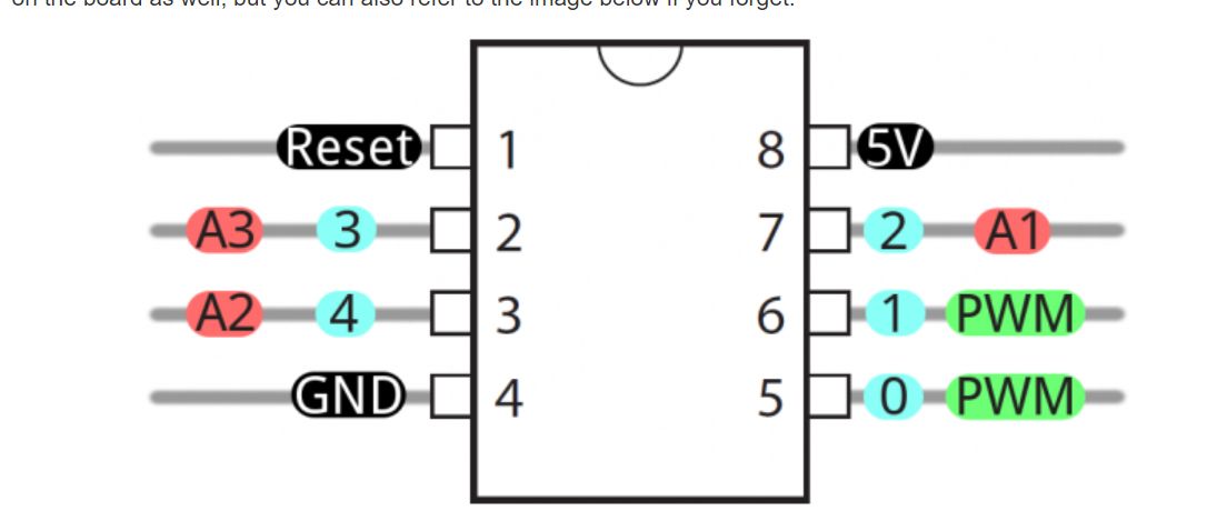
I really had trouble figuring out what pin numbers to put in the code. As I couldn't get the code to work. I first measured the voltage on the over the stretch sensor. You can see this in the second video above.
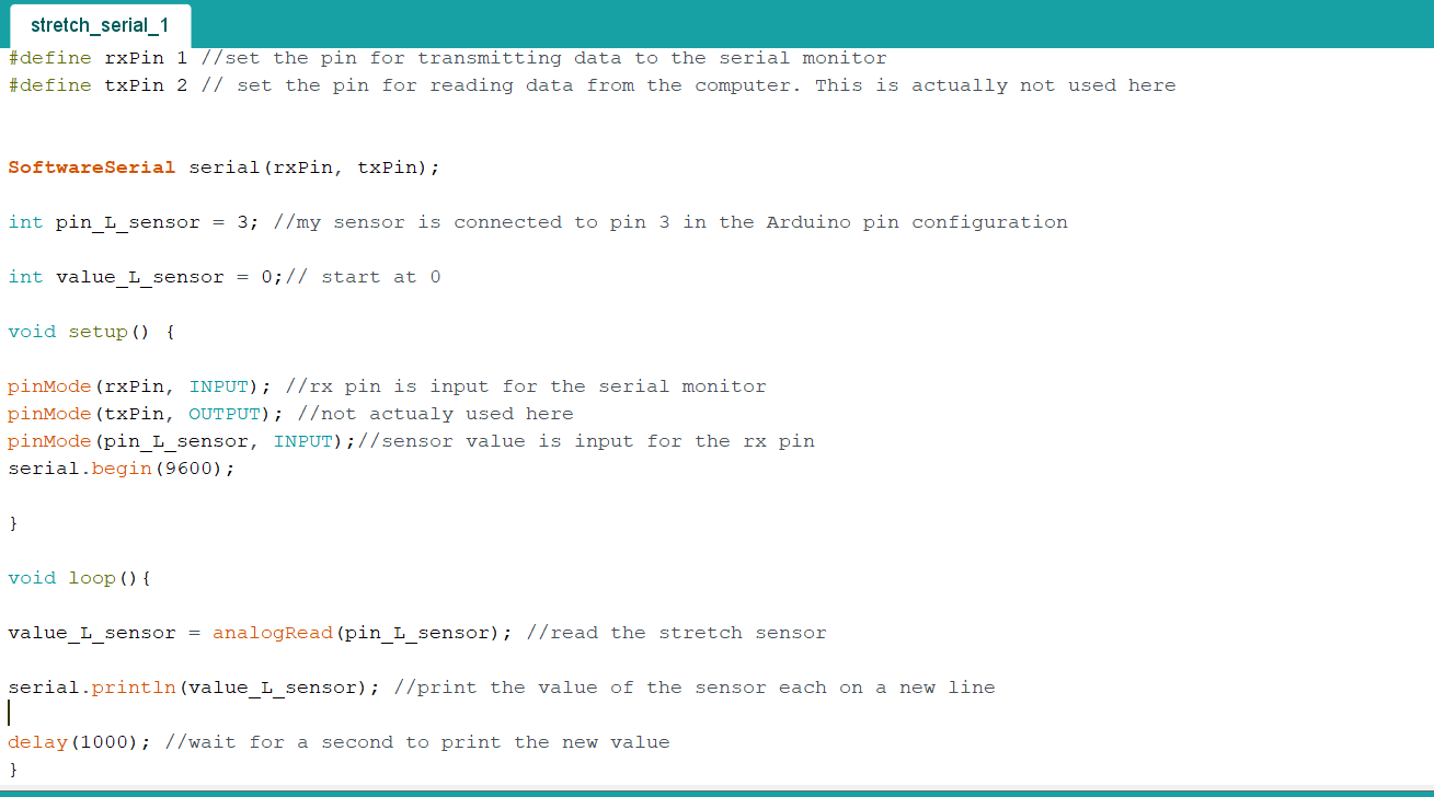
With help from Emma I adjusted the code hello_switch_serial. My sensor is on PB3 which corresponds to pin 3 in the Arduino software. I changed the rx and tx pin to 1 and 2 respectively. My board doesn't actually have a tx-pin, but since I will not be reading data from my computer it should be okay. On my Attiny board my rx pin actually corresponds to pin 2. But I recall something about changing those pins around in your code. It still confuses me.The fact that I denominated the rx pin to 1 on my Attiny, that in my schematics is actually MISO, doesn't matter because you use MISO and MOSI for programming your board. As soon you have programmed your board, you can use your MISO and MOSI pins for other purposes.
When I got the code working, I saw that the output was a steady 1023. When again Emma and I measured the voltage on the PB3 pin, we did measure a varying voltage with stretch. I seemed that the alligator clips where not connecting to the Lily pads. So I soldered wires to the pads and connected the board again.And then it worked! You cn see it in the second video above. The values varied from around 600 unstretched to 200 stretched. The values start changing only if you allready strain it al little. I wonder if I can get that kind of stretch in my final project. I will experiment some more with this. The code I used is here: Explaination you can find underneath.