Week 12: Output Devices
This weeks assignment is: add an output device to a microcontroller board you've designed and program it to do something.
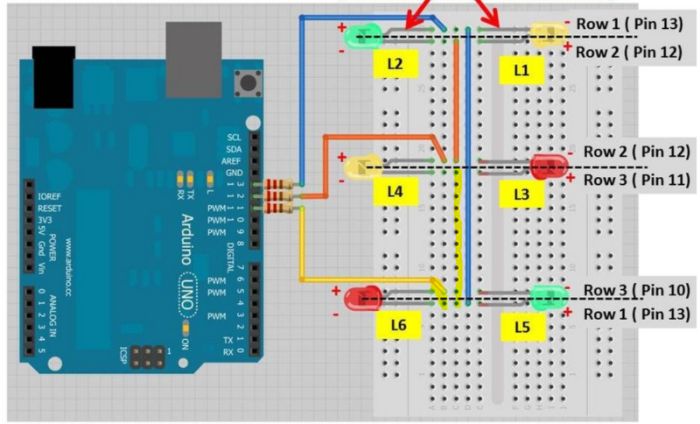
I have been asking myself: If I make a auditory sensory hair cell, as an educational model, what would be a biological meaningfull output? In the hair cell the stretch molecules that open up ion gates in the membrane, change the membrane potential. I could visualize that changing membrane potential by flashing LED lights along the surface of the cell body. Checking out the output devices that were discussed in the lecture today, I found that Charlieplexing would be the thing to do this week. Once again I searched the Fab Academy archives and found great work of Muhammed Jassel P and also of Marije Kanis. On Marije's page I found a link to an Instructables project doing Charlieplexing with Arduino Uno. I tried this, just to practice and get an idea how Charlieplexing works. Unfortunately there was a mistake in the picture on the wiring of the board, but I'm really proud to say I fixed that. There was a yellow wire missing and the first yellow wire was pinned in the wrong way. The bad wiring made the LEDs blink in the wrong order. The picture shows how I corrected the wiring, the video's show the wrong blinking and the right blinking.
This is the code I used:
Designing the board in Eagle
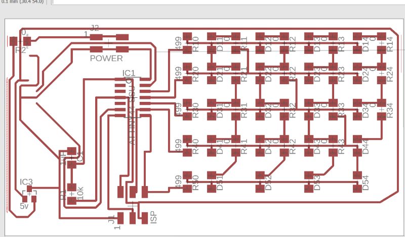
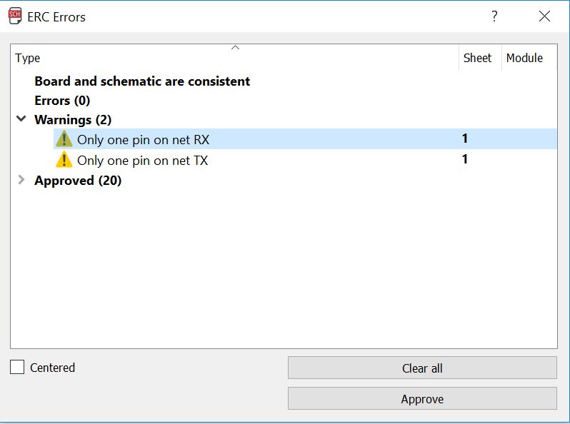
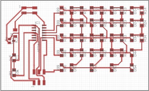
The board that Neil showed in his lecture looks like a lot of wiring in Eagle. Luckily Marije has shared her Eagle files on her web page. On her board she includes a FTDI header. I don't need that so I personalized her board by deleting the FTDI header. After that I did an ERC check. This gave me the warning that TX and RX only have one net on the Attiny44. Off course if I deleted the FTDI header, I don't need the TX and RX either. For security's sake I checked with Neil's board ans saw that he left pin PA0 and PA7 empty. I deleted TX and RX on the Attiny44. What I also noticed is that Marije uses the MISO and SCK pins as output pins. This is conveniant because they are on the right side of the board to connect to the LEDs easily and after programming, you don't need them in their MISO and SCK function. Now I had all the components on my board that Neil had. Except that I have to use an extra 0 Ohm resistor as a bridge. Neils puts a trace underneath the Voltage Regulator, but Eagle will not let me do this, probably because of my own Design Rules. Finaly I also changed some straight angled traces for 60 degree angles. Now it was time to make PNG files. At last I have a working routine for this:
- Make sure none of your layers exceeds the dimensions of your board to much.
- Make all layers invisible except for the top layer and the 20dimension layer.
- In the dimension layer; draw a rectangular (or any kind of shape) with an offset of 1mm around your traces. You might want to make your grid visible and set it a scale of 1mm.
- Now make all layers invisible except for 51 tdocu and 20dimension layer. In the 51 tdocu layer draw a rectangle with lines, an open rectangle, with an offset of 1 mm from the 20dimension layer.
- Select only the top layer and press file-export-image; 1000dpi and monochrome.
- Open the file in GIMP. Press Color in the toolbar and Value Invert. Press File-Export As and export as PNG file. You have your files for the traces.
- Select only the 20 dimension layer and export in the same way.
- Also open in GIMP and follow the same routine. You have your cutting file.
You can find my design files here:
Engraving and cutting the board
Cutting and engraving the board went really smooth. I'm starting to get the hang of this. But still Emma had to point out to me that 4 of my Attiny connections where short cutting. I checked the traces that mods showed after calculating the path. I think a saw a least one trace where it should be, but I'm not sure. I cut the traces with a stanley knife and after soldering the Attiny I checked again for shorts. No shorts there!
Soldering the board
Marije had put 5 400 Ohm resistors on her board. I wanted to know why. So I calculated what resistor value I should take on this site. The LED's are neither connected in series as in parallel. They should be able to be on independent of the other LEDS without burning up because. Therefor I will assume only one LED is connected to the resistor. I am going to put a 5V regulator on my board. From the datasheet I got that the forward voltage is 1.8V. For forward current I took 5mA. This gave me a resistor value of 680 Ohm. In the lab I can choose from 499 and 1 K Ohm. The first is closer to 680, so I choose 499 Ohm resistors. Just like Marije did. This is the list of components on my board:
- Attiny44
- 5V regulator
- 1uF Capacitator
- 10K Ohm resistor
- 5 x 499 Ohm resistor
- 16 x 0 Ohm resistors
- 20 x Green LEDs
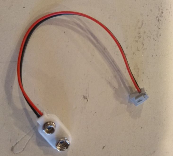
- 4-pin battery connector
Preparing the board
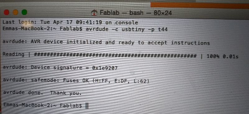
To check if can program my board, I connected it to my programmer. In the terminal I typed avrdude -c usbtiny -p t44 and I got the message my computer can see my programmer. yay! Now in the Arduino software I imported the right board type. In preferences I pasted the link. In tools I selected the Attiny44, 8 MHz internal clock and the USBtiny programmer. And I burned he bootloader. This was succesfull.
Programming the board
The first thing I did is just try the code I used for the Arduino test. See the video underneath for the pattern of LEDs turning on and off.
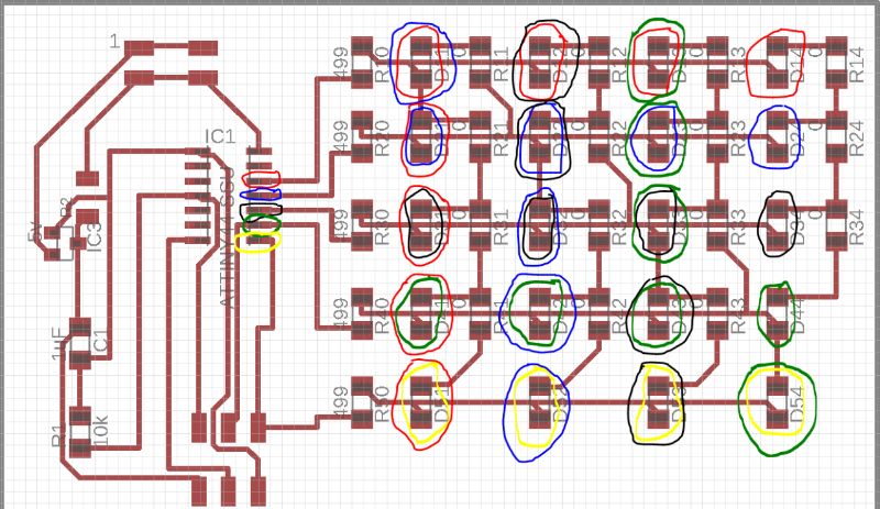
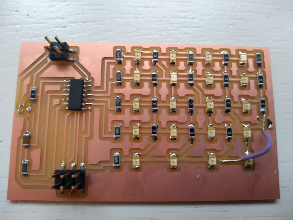
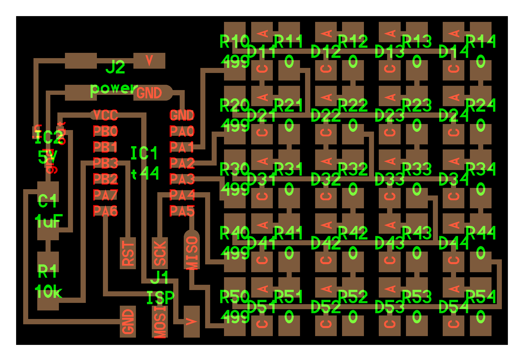
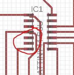
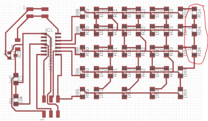
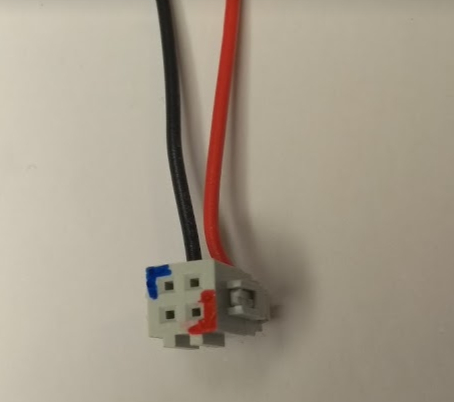
Now to understand why exactly these pins are responding to the code, I really need to understand what the connections are in my board. So I marked all my pins with colors corresponding to the pins they are connected to. So in the picture above you can see the result. The outer 'circle' shows what pin the anode of the LED is connected to and the inner 'circle' refers to the pin the cathode is connected to. So for instance the upper left LED, LED11; the anode (blue) is connected to ATTiny pin 11 (Arduino pin 2)and the cathode (red) is connected to Attiny pin 12 (Arduino pin 1). You can see here that the anodes of LED 14, 24, 34 and 44 are not connected at all. Here I found out that the design is missing a trace connecting Attiny pin 8 to the anodes of these LEDs.
Now I understand how the LED's are connected on my board, I can modify my board so that it gives me the out put I want. For my final project I want a light signal along the surface of my sensory hair cell. So I might want rows of lights going on and off following up eachother. I finally managed to do that. See down here for the code I used and the result on the board. The next morning I soldered an extra wire where it was missing and all the LEDs blinked as they where supposed to.
Code Charlieplexing the rows alternately on my Attiny44 board
Explaining the code
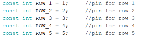
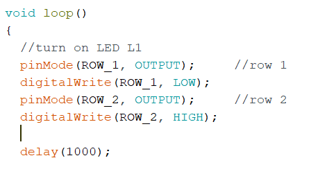
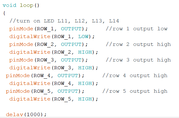
First you have to tell the Attiny what pins you are using. See the first picture down here. To turn a specific LED on, you have to set the output of the anode pin to HIGH and the output of cathode pin to LOW. In this way you set the anode on 5V and the cathode on GND. This means you have a voltage difference and you have current and you have light. To turn on LED 11 on, you write the code as in the second picture underneath. To turn on a row of LEDs that all share the same cathode, you write the code in picture on the right. Notice I am not using Input LOW in my code. Because I am turning on rows that are all connected to the same cathode, I don't need that part of the code.