Week 14: Networking and Communication
Working on my final project
Allthough it is not exactly necessary, I will implement networking in my final project so I can start working on it from this week on. The idea is use a bridge with a flex sensor and several nodes with a string of leds. The more the flex sensor is bend, the more nodes respond with lighting their string of leds, mimicing an action potential along the cell surface.
The Bridge
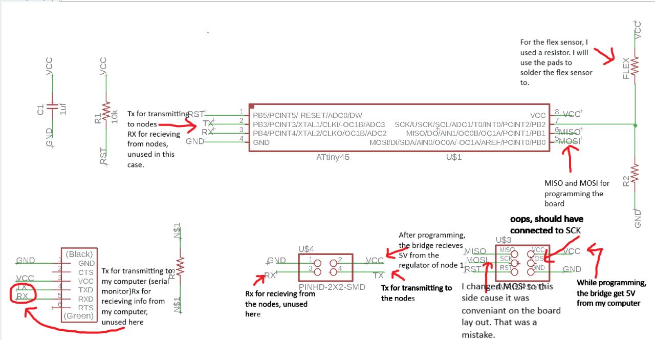
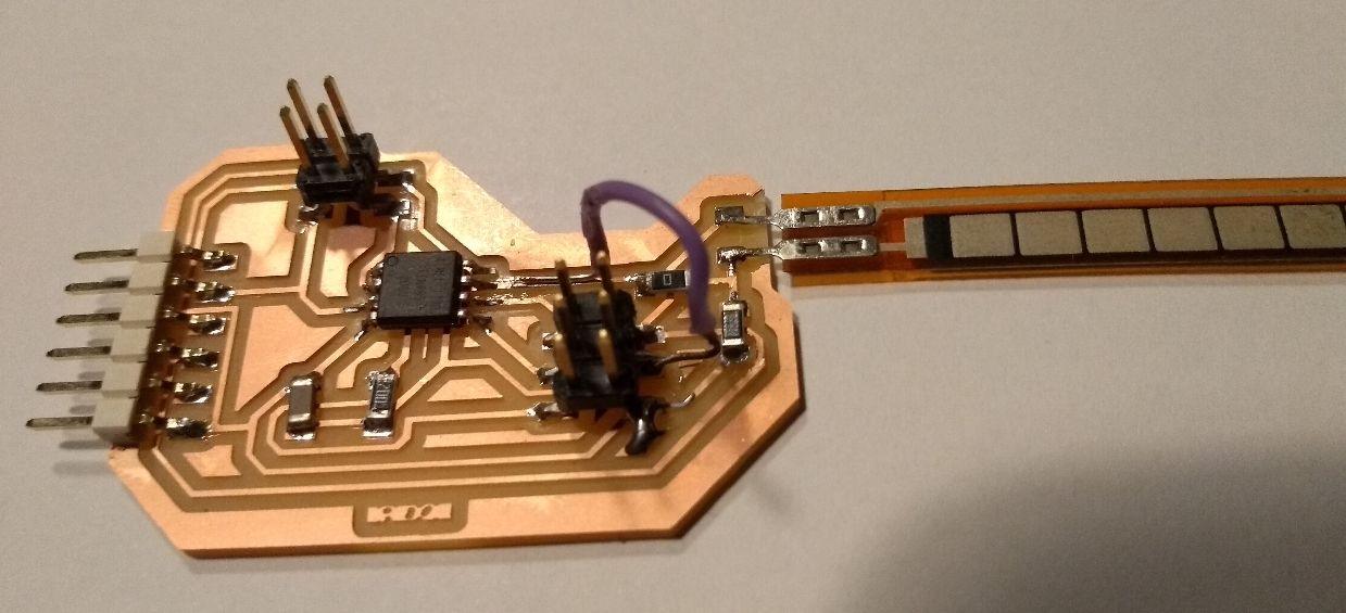
For the bridge I used Neils' design that he showed during the lecture. Instead of a LED, I have put a flex sensor. In the following picture I explain all the components on my bridge board. I made to mistakes on this board, both on the ISP 6 pin header. First I changed the MOSI pin to the other side. This was while I was designing the board lay out. It was just conveniant for the connections I wanted to make. I didn't think of the pin header on my programmer it had to correspond with. I solved this problem by using jumper wires for programming this board. This allows me to connect all pins individually. The second mistake I made was not connecting SCK on the ISP header to the SCK pin (7) of the Attiny. After milling and soldering the board, I soldered a wire from the pin header to the SCK pin on the Attiny.
The nodes
The bridge will send a signal to the nodes. When the flex sensor is bend only slightly, only node 1 will respond, a stronger signal will make node 1 and 2 respond subsequently, the strongest signal will make all nodes respond, turning on their leds subsequently. Here is another picture explaining the components on my node board.
Mistakes on my node board
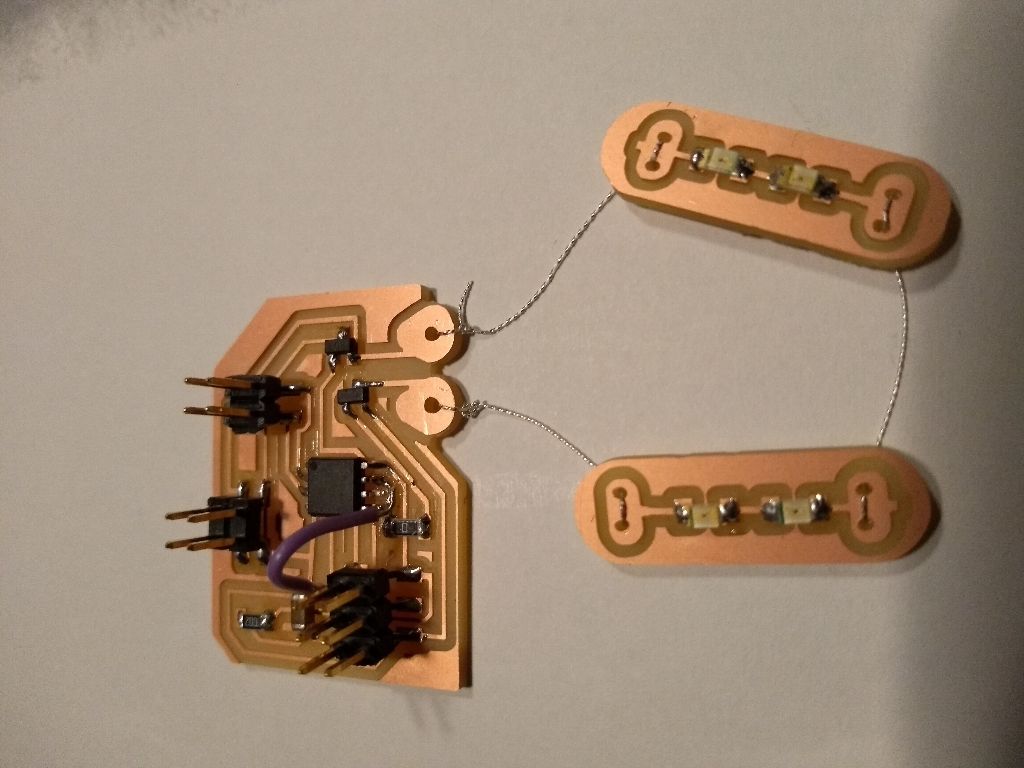
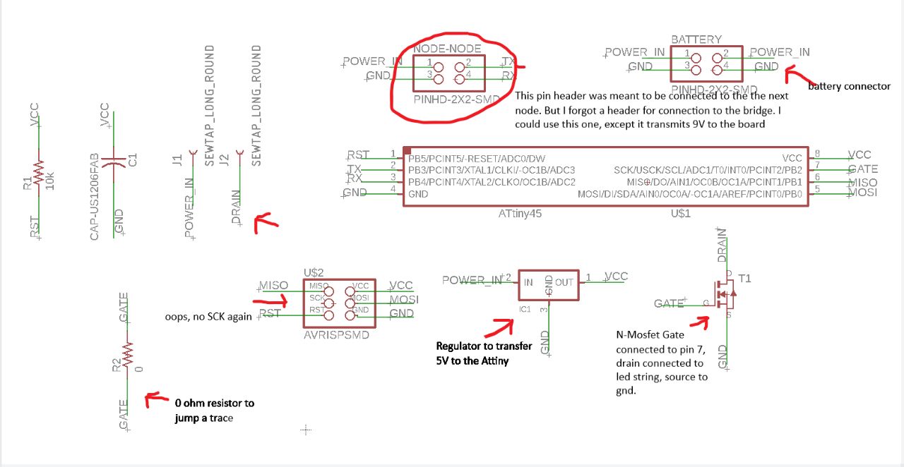
On my node board I also made two mistakes. The first one is like the bridge board; no SCK connection between the ISP header and the attiny85. So i soldered a wire again. The second mistake I made is that I added a 2x2 header for connection to the next board, but no header for a connection to the bridge. I could use the node-node connector, except that it would then transmit 9v (POWER_IN) to the bridge board. I will have to use jumper wires again to solve this. On the picture on the right you also see a string of LED beads I designed.
using a mosfet
I have been reading and watching online resources on what a mosfet is and how you use it. i will use a N-channeled MOSFET with which you connect the gate to the output-pin, that is either 5V or 0V. The source is connected to GND and the Drain to the component you want to put there. In my case a string of LEDs that are alo connected to a 9V battery. The reason to use a MOSFET in my project is because I want to light multiple LEDs. If I connect them in series, the current (I) will stay at 20mA, the forward current of one LED. But electronic rules dictate that the voltage (V) counts up in series. According to its datasheet each (green) LED will demand a forward voltage of 2.2V. So If I want more then two LEDS (and I do) the LEDS will dim, because the Attiny pin will only provide 5V. If I connect the LEDs in parallel, the Voltage demand will stay at 2.2V and the current will count up. The Attiny pin also has a limit on the currrent that it can sink. But this can be solved with a MOSFET, which is a kind of transistor. I this case I can use a MOSFET to open another circuit in which my LEDs pour current from a battery. At the same time the current in this second circuit is controlled by the MOSFET at a cost of the MOSFET heating up. Great resources on MOSFETs I found here and here. And great tutorials I found here and here.
One can calculate how much the MOSFET will heat up with the current demand you are putting on in. You will have to check the data sheet of the MOSFET you are using. You want to know what the so called Static Drain-Source On-Resistance is with the Voltage you put over Gate and Source. My datasheet gives a Rds-on of 0,125 Ohm for 4,5Vgs and a Rds-on of 0,085 Ohm for 10Vgs. As 5V is close to 4,5V, I wil take the highest value for Rds-on and add another 20% to be safe. That gives me a Rds-on of 0,15 Ohm. Heat is generated by power. And power (P)=R*I*I. With 10 LEDS I will demand 200mA of current, so P=0,15*0,2*0,2 = 0,006W. In the datasheet of the MOSFET you can also find that it heats up 250 degrees C for every Watt. So 0,006W gives a 1,5 degrees C rise in temperature. I guess I'm safe.
String of led beads
The idea is to have a string of LEDs turning on and off along the cell surface. I designed a bead holding two LEDs. The button holes can be used to either connect them in series or parallel. I used the button holes from the Lilypad library in Eagle. I have used conductive yarn to connect them. specs conductive yarnWhen soldering the LEDs on the board, I took care to put them in the same orientation. The green stripe is the cathode. When connecting them to the node board I took care to connect the cathode sides to the Drain and the anode sides to POWER_IN.
Programming the network
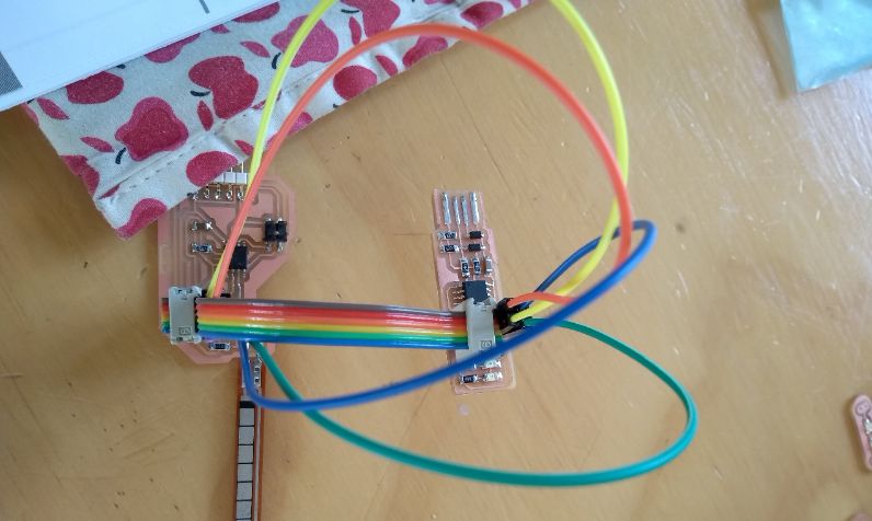
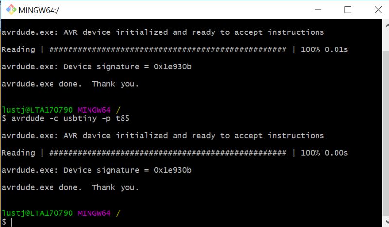
First I checked if my computer could find my boards. For this I first connected my bridge board to my programmer. Because I switched SCK and MOSI on my bridge board, I had to use jumper wires to connect both ISP headers. It looked like the picture on the left. I opened my git bash terminal and typed avrdude -c usbtiny -p t85 and my terminal showed my board is visible. After that I did the same for my node. Also very visible for my computer.
Then I wanted to test input and output on both boards. So I programmed my bridge board with my previous "serial stretch" code, that I used in the Input Devices Week (11) and the Interface and application Programming Week (13). I changed all the corresponding pins. Also in the Arduino software I changed attiny45 to attiny85. When I opened the serial monitor, it gave me a value around 860 and no matter how I bended the flex sensor, the value wouldn't change. I measured the resistance on this flex sensor before soldering it to my board, just to decide what value of resistor I had to put on my board. Then I measured values in between 8000 and 16000 Ohm. When Emma helped me out, she measured a short on my stretch sensor, but we couldn't actually see what was making the short. I took of the stretch sensor. Nothing strange to see underneath the sensor though. When i tried to connect the board to my FTDI header again to see what values my board was spitting out now, without a sensor, I wrecked the FTDI header. It came off, copper and all! Now there was no way for me to test my output on this board. So I decided to use my stretch sensor input board from week 11 as a bridge.
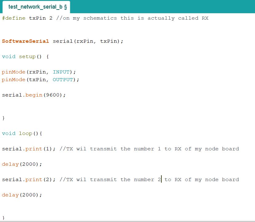
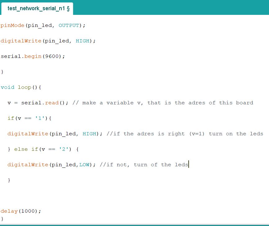
Then I used Emma's example of the serial network codes for bridge and board. I changed pin numbers accordingly and programmed both boards. Then I connected the boards and connected the 9V battery to my node board. I used the ISP header of my stretch sensor bridge board to connect TX, VCC and GND. In the schematics of my stretch sensor board, I used my so called RX pin as a TX pin. On my node board I connected RX and GND from my NODE-NODE header. And connected to the VCC pin of my ISP header, otherwise I would put my bridge board on 9V. I worked! I saw the LEDs going on and of with an interval of 2 sec. Check out the video above here. Underneath I explain the test codes.
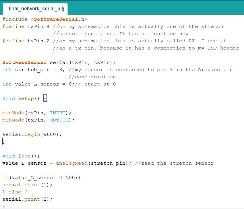
Now I was confident to try to make my own code for this small ntwork. In the pictures underneath is my first attempt. The idea is that the bridge board signals "1" if the stretch sensor value goes under 500. When the value is bigger then 500, it signals 2. I chose 500 as a treshold value because earlier, in the serial monitor, I learned that my stretch sensor value changes in the range of 300 to 800, going down when stretching. Unfortunately, I doesn't work.
As I was tinkering with my network I suddenly blew op something. I had tried to connect the battery and accidentally touched cathode with cathode and anode with anode. A small black puff of smoke came out of my node board. I desoldered the regulator and checked If my computer could still see my micro controller. This was luckily the case, so my MC was intact. I soldered on a new regulator and left it at that for that day.
On Friday Emma and I spend quite some time debugging the code and the network. We checked for shorts and missing connections. I tried the test code again. That worked again. We tried my code and then connected the bridge to the serial monitor: I was sending 1 and 2 according to the stretching of the sensor. I even desoldered and soldered a new regulator. In the end I changed the conductive yarn for actual wires. And then Emma discovered that there should not be a delay in the code of the node. I got rid of that and then it worked! The LEDs responded really quick to the stretching of the sensor. Curious for the effect of a bending sensor on this network I Then connected the bending sensor to the pads of my bridge with crocodile wires. I programmed my bridge with the serial_stretch code from week 11 to check the sensor values of the bridge in the serial monitor. I saw that the values went up with the bending of the sensor. That is the other way around from what my stretch sensor was doing: values went down when stretching. The bending sensor varied from 630 to 780. So instead of if(value_L_sensor "smaller then" 500) I wrote if(value_L_sensor > 700). That made the LEDs respond really nicely to the bending of the sensor as is shown underneath:
And here you can find all of my files: