Week 5 : Electronics Production
How to use the small milling machine
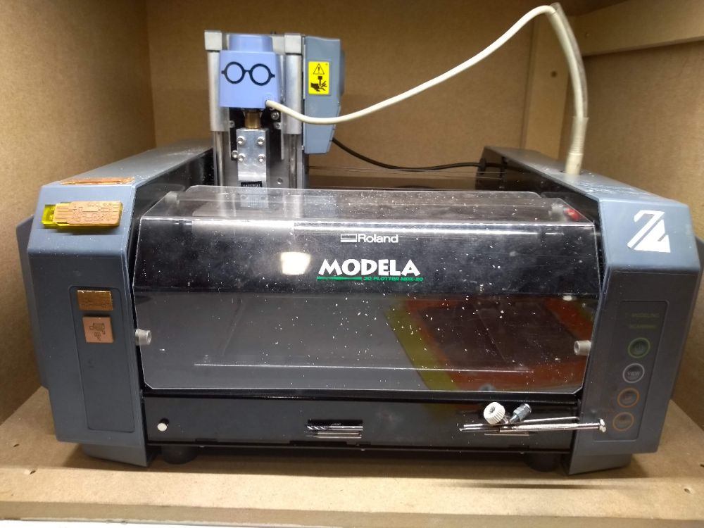
The assignment for this week is to mill, solder and debug an in-circuit programmer. Later on we will use this to tranfer code to a micro controler (=integrated circuit). We are using AVR, which is a family of micro controlers. The template we will be using is of a guy called Brian and to be found here. The milling machine, a Roland Modela MDX20,forms paths along the back/white border in png-files. The software we are using to calculate these paths, is the third version of Fab Modules, designed bij Neil Gershenfeld, called Mod. The material we are using is fr01 board, wich has a copper film on a paper based underlayment.
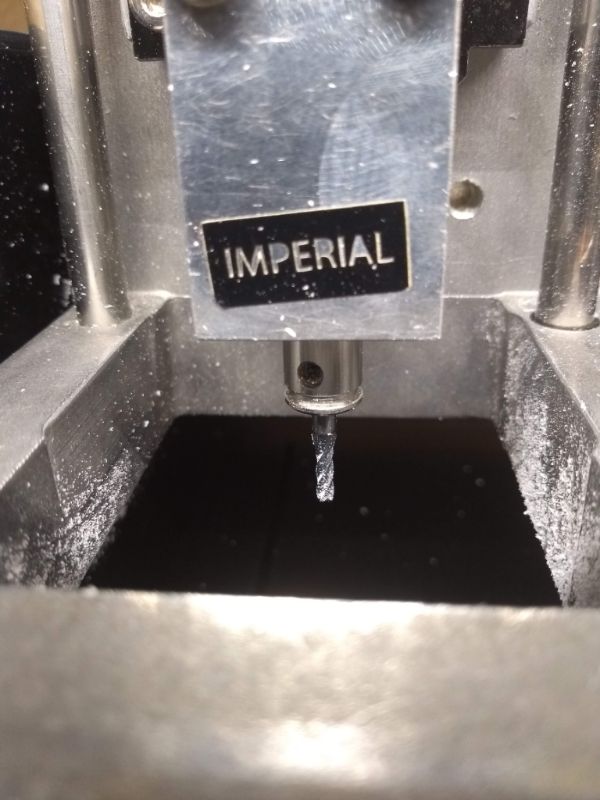
To mill a intergrated circuit programmer, you need two files; one to engrave the copper and one to cut the outline. Engraving is done with an endmillof 1/64 inch, or 0,4 mm. The cutting is done with an endmill of 1/32 inch,or 0,8 mm. The final board will be Surface Mounted Technlogy (SMT), because the corresponding components are smaller than with Through Hole Technology.
Prepare the milling machine Roland Modela MDX20
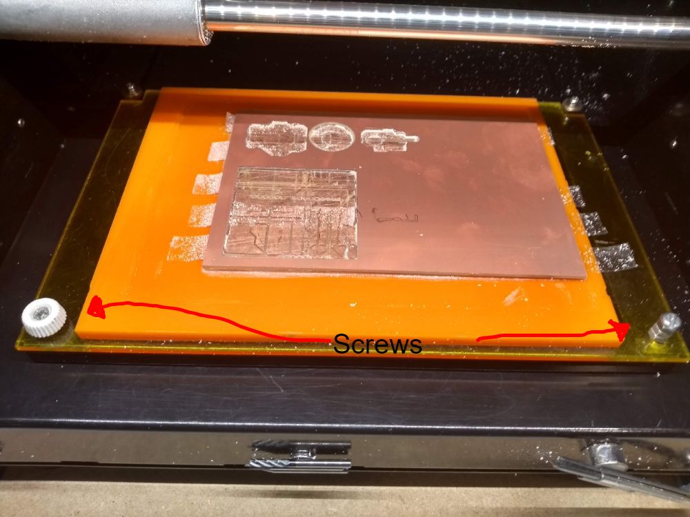
Turn it on. Remove the bed, by unscrewing the screws. Put the screws on the magnets. The bed consists of an acrylic underlayment, a sacrificial copperplate and on top of that the copper plate you want to engrave and cut. Both copper plates are fixed with double sided sticky tape. Unusable plates can be removed with a spatula. After this you wash the underlying plate and get rid of all sticky left overs (sticker solution), dust and paper fibers (vaccuum cleaner). Make sure the plate you are going to engrave is super horizontal. As you are working in tenths of mm's, every speck of dust can spil the engraving.
If the sacrificial layer is squeaky clean, you put on new sticky tape to mount the copper plate you are milling. Leave room between the tape strips, to avoid overlapping. Then firmly press the copper plate onto the sacrificial layer. And place back the bed.
Preparing the png-file with Mod
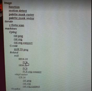
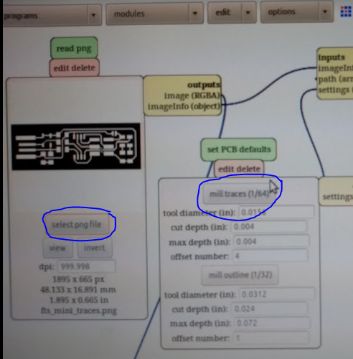
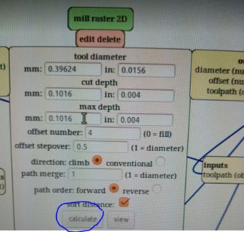
To prepare the file for the milling, one opens Mod. A short cut is found on the desktop of the adjacent computer. Brian's template is allready in one of the folders. Open the template (.png) in Mod by pressing select png file in the first block. The left picture down here, shows which folder to open. Select in the second block: mill traces and set PCB defaults. (Picture in the middle) In the third block press calculate. (Picture on the right) The milling machine works in layers. For engraving,one layer is enough, therefore cutting depth = max depth. Stepover offset = the space between the paths the endmill makes, expressed in a percentage of the diameter of the endmill. 0,1 = 10% overlapp, 0,9 = 90% overlapp. the best offset is between 0,5 and 0,8. Path merge can be left at 1. Speed and force are by default.
Back to the machine
Put in the right tool with an Allen key. Don't use to much force on it. Put in values of x and y in the last block in Mod to set the endmill on exactly the right spot. Try to spill as less material as possible. The endmill will start left under. If you have the right spot. Unscrew the endmill and place it gently on to the copper. Then fasten it again. Turn it a few times to get rid of specks of dust. Now make a note of the coördinates of the origin. This is the same origin you have to use if you are cutting the outline. Every time you set a new origin, you press calculate. Click the shortcut serial server to make a connection between the computer and the milling machine. Now send the file. The milling machine will start engraving. As long as you see lost of dust, it should be oké. Press view mode if you think something goes wrong. Press view again to go on.
Milling problems and their solutions
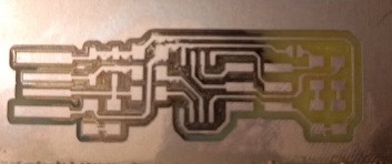
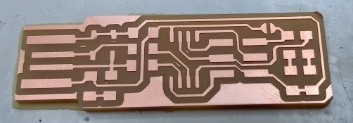
After this the milling looked great. See for yourself in the middle picture up here. The right picture is my completely soldered PCB. I will tell about that later on. After the succesfull engraving, I needed to cut the PCB.
Cutting the PCB
If the machine is done milling, press view on the machine itself. Turn the mill up, using the arrow. Now change the endmill for a 1/32 inch endmill.T Move to the origin you set for the engraving. In my case that was x=17 and y = 35. After this do the Z-calibration by bringing the endmill down to the copper and tighten it. Now open the cutting file. Select mill outline. Press calculate. Leave offset at 1. It will cut in three layers of +/- 0,6 mm. One layer has a maximum depth of approximately 2/3 of the diameter of the endmill. Then send file again. When the PCB is finished, scrape of the rest of the copper in front of the USB connections with a sharp knife. And off course clean the machine with a vaccuum cleaner. Clean the milling bed with sticker dissolver after you removed your plate.
Assembling the PCB
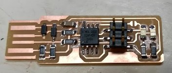
For assembling I gratefully used this tutorial. Allthough it tells you to solder the ISP header last, I soldered it first. Otherwise I would not have been able to to reach the pins. All the components are very small. And because I could not tell a diode from a capacitator yet, let alone the green from the red LED, I put pieces of sticky note on my bench with the name of the components. I used a Weller WES51 for soldering and set it at 700 Fahrenheit. The soldering tin had a small diameter, I think +/- 0,5 mm. When starting with a new component, I first heated up the copper and then brought in the tin for a tiny drip. Then using a tweezer I held the component where I wanted it and heated the contact point and the drop of pin at the samen time. When I was satisfied with the result, I soldered the rest ofthe contact points. For this I heated copper and contact point at the same time and then brought in the tin. The result is shown in the picture on the right, above this text.
Testing the soldering
After inspecting the board with the eye, I checked for short circuit between VCC and GND using a multimeter. Look for the continuity sign on the multimeter. Check if the buzzer goes when the two probes touch. When it does, you know it works properly. The multimeter should make a buzz sound in case of a short. I touched VCC and GND with the probes. No buzzer. Yihaw! After this I put extra traces of solder on the USB connection copper and filed it to make it even. Also I made the PCB slightly thicker with some double sided tape and a piece of paper, which I cut out following the outline of the PCB with a Stanley knife.
Software Installation
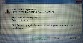
I started with the tutorial for Windows. Unfortunately the link to the AVR toolchain for windows led to an unknown page. I found an alternative here All went wel. Then it was time to install GNU Make. This didn't work. I got the error in the picture down here on the left. It says
Error creating registry key:
HKEY_LOCAL_MACHINE\Software\GnuWin32
RegCreateKeyEx failed; code 5
Acces is denied Trying installation on my android phone
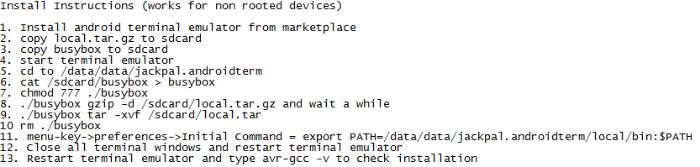
In the evening of monday 20th I found some files here including a readme text that promissed me toolchain,avrdude and make for my android phone, noting that I would need a cable that turned my micro USB port into a actual USB port. I followed the instructions in the readme file. You can see them in the picture on the right. It got me pretty far. I needed to adjust the path to the acual folders my phone had put the files in. For this I also needed to download a file manager for my Lenovo Moto G(5S). But installation step nr. 11 just didnt work out. I gave up.
Getting it done on a Mac
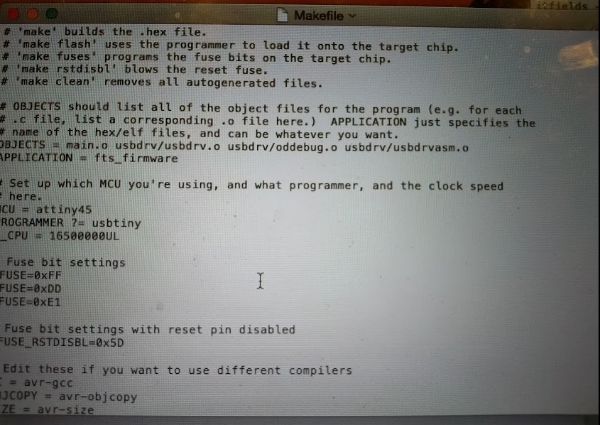
Luckily there was a Mac in lab I could use. I followed along this tutorial again. First it told me to update the Makefile for the type of programmer I was going to use to program your board. The Makefile, by default, assumes that you're going to use a programmer in the usbtiny family (e.g. another FabISP board). I checked the make file and the programmer allready was set to ATtiny45. You can see this in the picture down here on the left. I liked the extra explainatory in this file telling me what all the commands mean that I am going to execute.
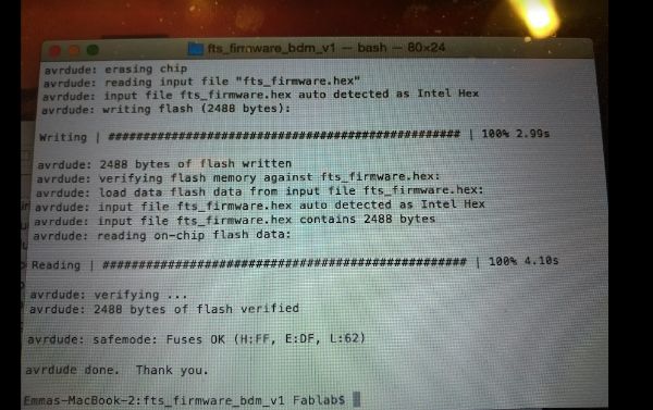
Then I plugged my board into the USB-port. The red light lid up, so that was great. I connected the programmer to the ISP header on my board. The I ran make flash. This erased the target chip, and programmed its flash memory with the contents of the .hex file I built before. This looked wel as you can see in the picture on the right. AVRdude is a very polite dude,saying thank you all the time.
After this I set the configuration fuses. First I set the fuses that control where the microcontroller gets its clock source from. This will allow to check that the board works as a USB device, but it won't yet be able to program other boards. I ran the make fuses command. This sets up all of the fuses except the one that disables the reset pin.
Testing USB functionality
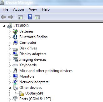
This I did on my own laptop again. I found it under Device Manager, other devices. See the screen shot under here. Last thing to do was to blow blow blow, blow the reset fuuuuuuse! (Björk forever). For this I connected the ISP programmer to my board one more time, and ran make rstdisbl. This does the same thing as the make fuses command, but this time it's going to include that reset disable bit as well. The tutorial tells you to get rid of the jumper connection, but Emma told me not to do this yet. So, I was done for the week.
Update
Ever since I made this ISP programmer, I have been succesfully programming my boards with it in week 7, week 9, week 11, week 12, week 13 and week 14.