Week 8: computer controlled machining
designing a dresser in Fusion 360
At the start of the week I was going through nice Pinterest pictures for a big CNC design. In the back of my head was a little voice saying: "keep it simple, you have so much work to do for last weeks assignment." If only I had listened..
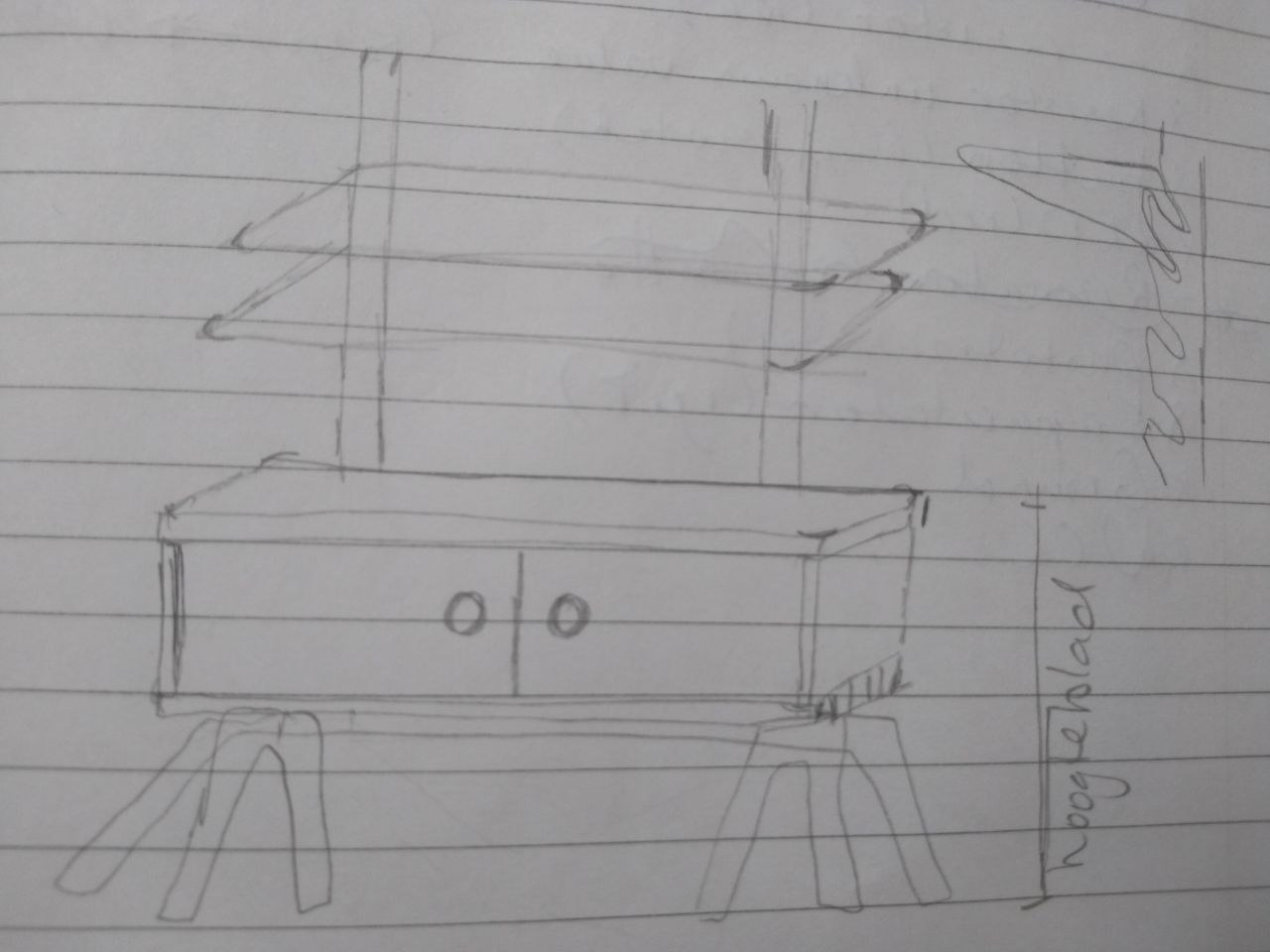
I decided to make a dresser for our living room. It had to be narrow, but could have some height for the place it was supposed to be. Underneath is the sketch I made. The idea was to make it have sliding doors and a flexible holder to put on shelves. The last idea I had to let go of because of shortage of time. Also I ran out of time to much to also design the doors.
tutorials I used
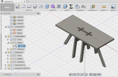
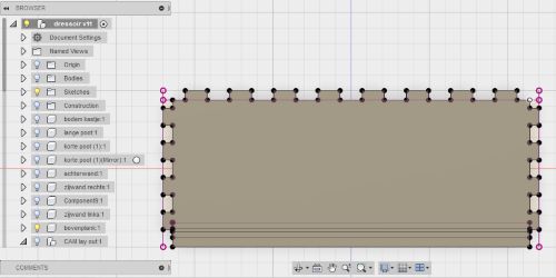
But very much unaware of all the troubles I would encounter in the near future, I started drawing in Fusion 360. I used two tutorials: One for the legs: A tutorial for a stool. And one for the body: A tutorial for a press fit box. If you want to make something simular in Fusion 360: KEEP TRACK OF YOUR SKETCHES, BODIES AND COMPONENTS BY NAMING THEM. Make sure you organise them in such a way that you can always find them back.
Aligning the legs and the bottom panel.
When I had drawn the bigger leg and the two smaller legs, I wanted to align them to the upper panel of the bottom of the dresser. In that way I could draw a slot around the legs to fit them in. I followed this tutorial for aligning. Under Modify, I clicked the Align tool. Then selected the upper plane of a leg and after that selected the upper plane of the bottom panel of the dresser. After this the leg might still not be in the right place on the X/Y plane. For this you can use the Move tool.
Drawing slots, avoiding constraints
When drawing the slots on the side and back panels, I found that because of earlier sketches and construction lines, Fusion 360 , when you try to draw a rectangular, automatically snaps to previous drawn points. If you try to dimension them afterwards, you get the message that you are overconstraining the sketch. I tried to make all of the other sketches, bodies and components invisible, but that didn't help. At that point I solved this by repeatingly drawing a rectangular that didn't hit previous drawn points. Fusion 360 has a function to isolate a component. Maybe this could help. But then you should first create a component out of a body by right clicking on the body in the browser and choose; create component out of body.
exporting sketches to DXF
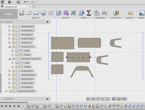
Then it was time to export the design to a DXF file for computer controlled machining. I had layed out all my components of the dresser in a X/Y plane that had the dimensions of the sheet of plywood I was going to use. I though I could then just select all the components and export to DXF. But fusion will only let you export sketches to DXF. I remembered Frank telling us that you could project all your components to a plane and export that projection. I tried selecting all the components and then choose Project in the Sketch menu. Fusion 360 would not allow me to choose a plane to project it on and when I clicked OK, I couldn't find the projection in the browser.
My problem was that I had drawn most of the panels of the dresser by first sketching a rectangle and extrude it. Then sketching a rectangular on the edge of the panel and extrude it. This made slot. Then make a rectangular pattern of it, creating more slots. By combining the panels and cutting them, made them fit together. With this workflow I didn't create sketches that I could use for milling. I decided to just trace all the panels of the dresser. This way I made new sketches of every component that I coud then export to DXF.
You can find all my DXF files here. The dxf file of the top panel I made later. As you can read later on, I made the mistake of using the bottom panel as a template for the top panel. But they are not the same, I found out. The files of the short leg and the side panel you have to use twice.
files dresserpreparing the files in Part Works
The software that turns the 2D vector-file into a G-code (a series of coordinates that tells the machine how to move) is Part Works. I opened it on the PC associated with the Shop Bot. This is the workflow I used to convert the files to G-code.
- Open a new file and set the working sheet to the dimensions within the screws you are going to place. This minimizes the risk of hitting a screw with the end mill. For me this meant setting the dimensions to 1200 by 2420 mm (instead of the real sheet dimensions 1220x2440)
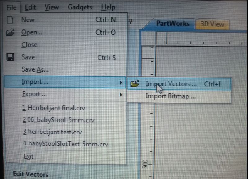
- Click: File-Import-Import Vectors. This I did for every part of my model, since I made separate files for them.
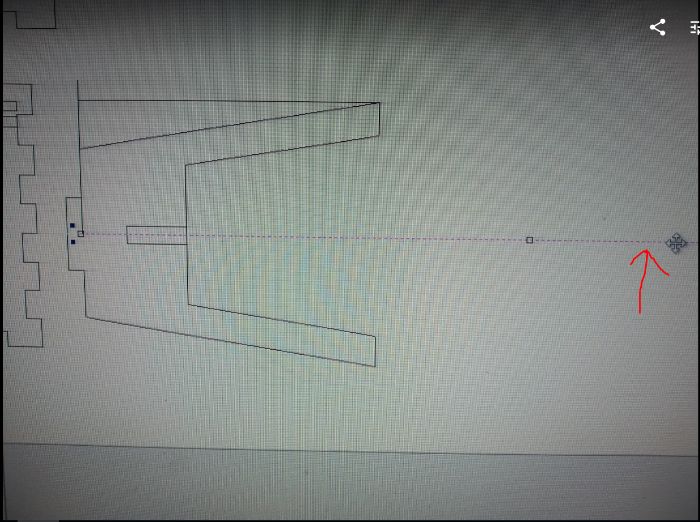
- Remove construction lines by selecting them and press delete.
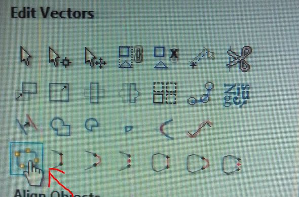
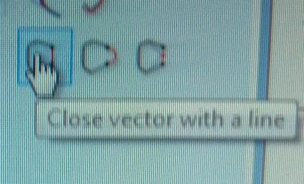
- When you remove construction lines it leaves a gap in the vector. You can close the vector with the icon in the picture.
- If for some reason you have missing lines, like I had, you can add them with the icon in the picture.
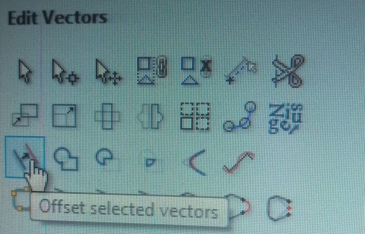
- If you forgot to account for an offset for your slots, like I did, You can use the offset tool shown in the picture. I chose an offset of .25 mm. After that you delete the part without the offset.
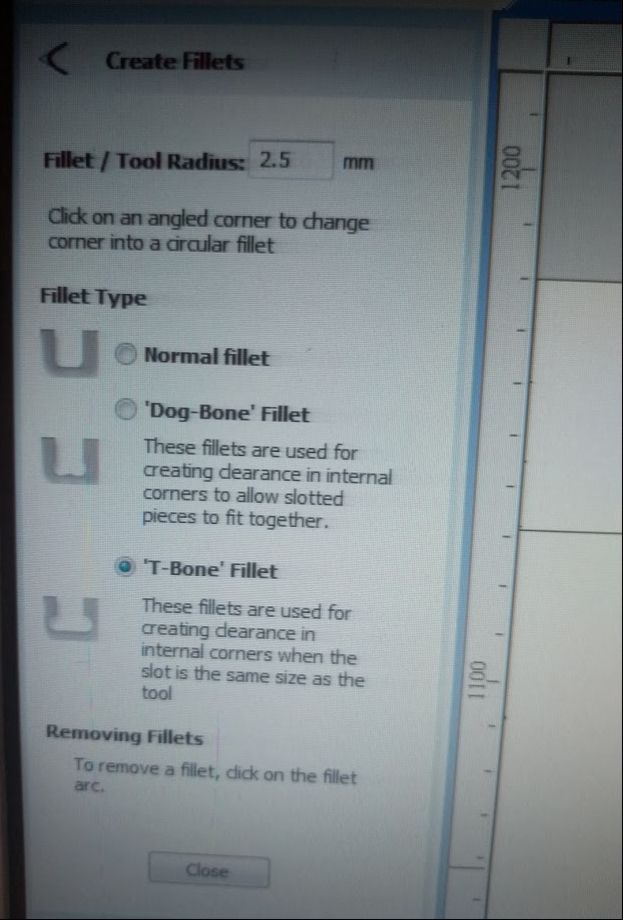
- Add a fillet to all your inner corners. I chose the T-bone fillet because I like it better than the dogbone. Allthough for the sliding pockets I had to use the dogbones as there was no space for T-bones. The tool places a fillet in the corner 90 degrees on the line you choose to place it on. Just click the line you want it on.
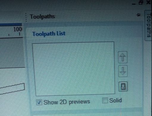
- Now define your toolpaths. I needed cutting as well as making pockets.
- First define an end mill. You can see the settings I used for the end mill in the picture: diameter = diameter of the end mill, pass depth = the depth of every stroke inwards your material, stepover = the overlap between the paths of the end mill when it is making a pockets, spindle speed = the speed with whic the end mill is turning around its axes, feed rate = the speed of the end mill on the X/Y-face, plunge speed = speed in the Z-direction.
- For the pocket toolpath I used the settings as shown in the picture. Except for the max depth; I set that to 5,3 mm. max depth = is the depth of the pocket you want to engrave. start depth = is the start depth of the pocket. In case you want to engrave a pocket into a pocket.If you choose offset that means the end mill will offset its way in the pockets, starting out the outer lines and ending in the middle. If you choose raster it wil engrave in a raster pattern.
- climbmeans the endmill will spin in the opposite direction of the actual cutting as shown in the drawing I made.
- If you are happy with the settings, press calculate. The software will show a 3D view of the path the end mill is going to make.
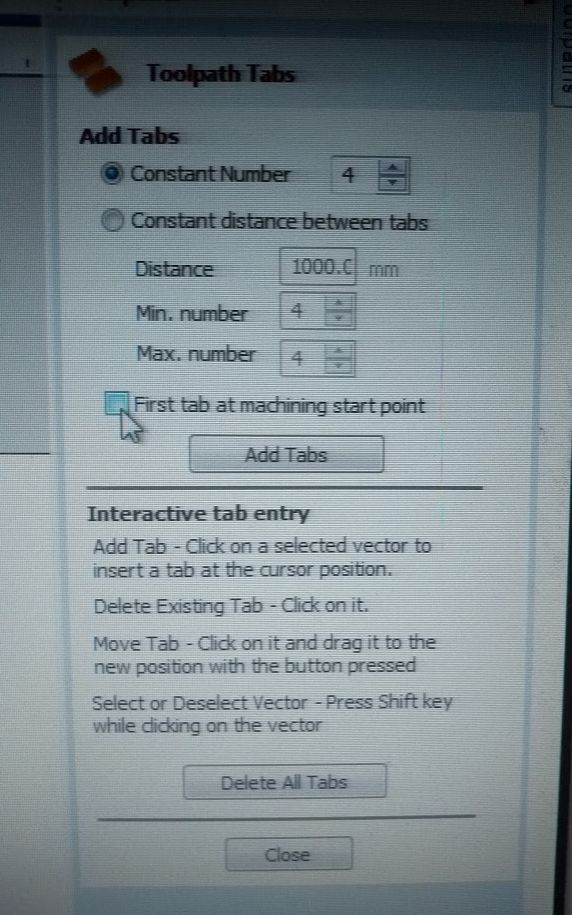
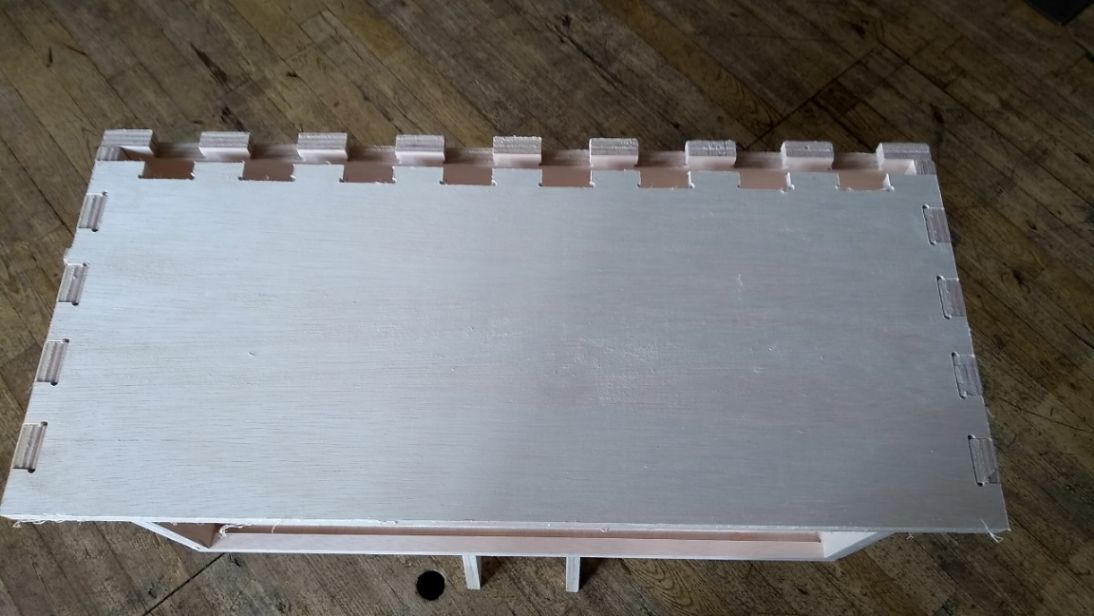
- Now select a toolpath for cutting by selecting the lines that need to be cut and then press the cutting icon. As you can see in the picture the max depth is now 15,5 mm, cutting through the wood that has a thickness of 15mm.These lines will need to be cot from the outside, I choose climb again. Then to add some tabs, select add tabs to toolpath andpress edit tabs. This wil add some patches that are not entirely cut through, so your parts will not fly all over the place when the come loose.
- I chose to add 4 tabs on every part.After the sorftware places the tabes on your cutting lines, you van drag and dop them on more conveniant places. For instance places you can easily reach with saw and sandpaper afterwards.
- Press calculate again.
- Then define another toolpath for pieces that have to be cut out from other pieces. You use the same settings as the cutting toolpath, exept that you choose innerinstead of outer
- Now you set your toolpaths in a logical order. First pockets, then, inner cutting, and finally outer cutting.
- If you want you can reset the 3D view and then click review all toolpaths to check how the machine will handle all the toolpaths
- If you are satisfied with what that lookes like, you can turn your attention to the machine.
- Save your file, it is a G-code now!
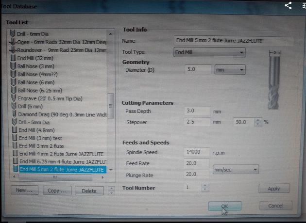
- Diameter:5mm
- pass depth 3mm
- Step over 2,5mm
- Spindle speed 14000 rpm
- Feed rate:20 mm/s
- Plunge rate:20 mm/s /ul>
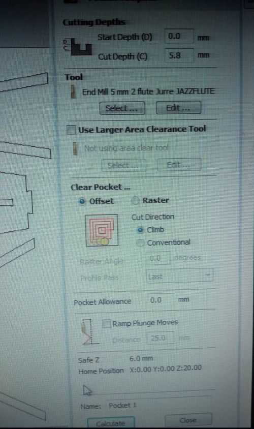
- Start depth 0mm
- Cut depth 5,8mm
- Clear pocket:offset
- Cut direction:climb
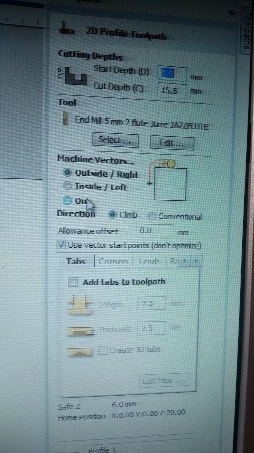
- Start depth:0mm
- Cut depth:15,5 mm
- Machine vectors:outside right
- Direction:climb
Working with the Shop Bot
Safety issues
A CNC machine is a big and powerfull machine. It will not stop I your hair gets caught in it or when the end mill is about the break off. In the last case it will be propelled into the room with potential damage to the people that work there. Also the machine makes a lot of noise. If working with the Shop Bot you need to wear safety glasses (not made of glass) and ear protection (plugs work best). Also no loose strings should hang from your clothes and long hair must be tied back.Preparing and stopping the Shop Bot
- Place your material on the machine bed and fasten it tight with screws. Make sure the inner dimension of the screws is bigger then the work sheet you defined in Parts Work. Check it with a tape measure.
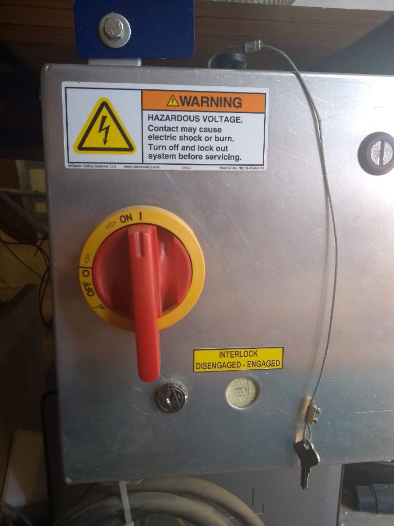
- First you turn on the machine with the big red switch on the right of the machine. You also turn on the external air exhaust at the wall behind the machine. A green light turns on. You also activate the air exhaust of the machine itself.
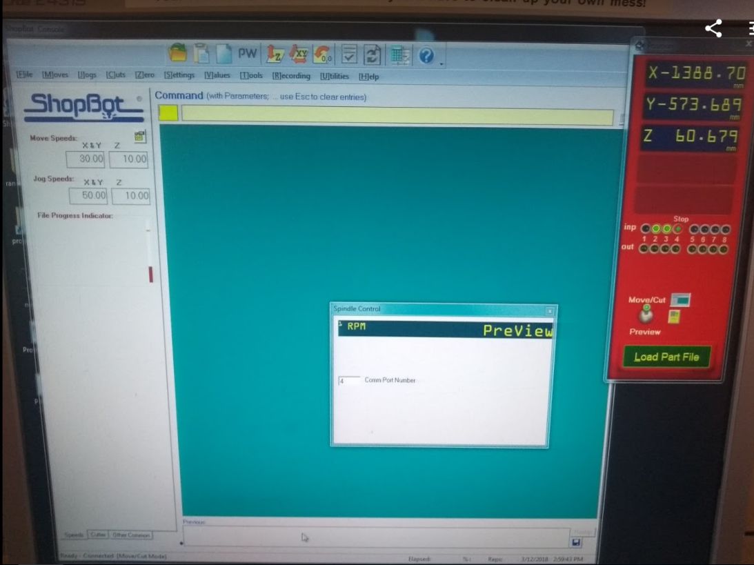
- After this you open the Shop Bot software.(picture)
- Press K on the keyboard, a remote controll for the robot appears.
- Move the robot arm with the arrows on the keyboard to a convenient place to change the end mill. If needed move the robot arm up with page up on the keyboard.
- First unscrew the protection cap with the wing nut at the back of it.
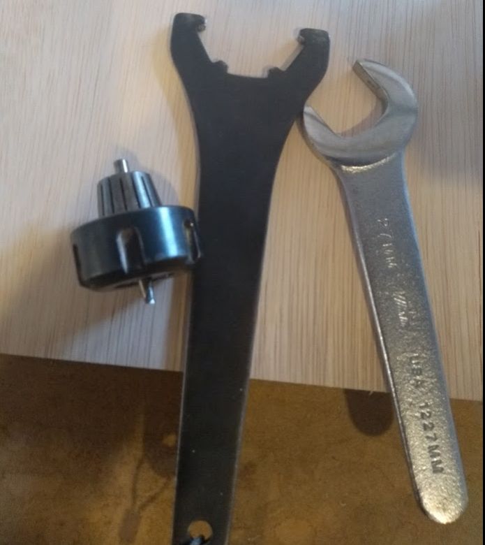
- Then unscrew the mill with the tools shown in the picture. For unscrewing you move the tools towards eachother.
- Put in the end mill you want to use.
- Place the mill back in the arm, screwing it very tight. (move the tools away from eachother.
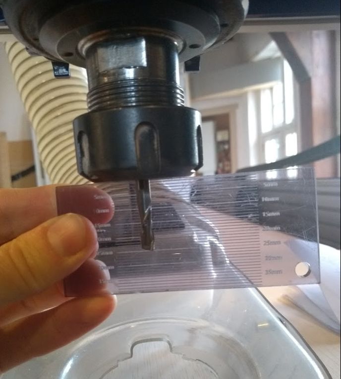
- The mill should extend at least the max depth you use in your file and a few mm's more. As you see in the picture, the end mill is out 24 mm.
- Now you calibrate the 0 on the X/Y plane. Press the X/Y icon in the top of the screen (picture).Move the mill to the point you don't want it to exceed. This will be somewhat inside of the most right screw. This is the point down left of your file in Parts Work. If you made your worksheet smaller than the inner dimensions of your screws, the mill will not touch the screws during its work.
- Make a note of the X/Y coordinates (In case you need to start over again) and tell the machine to use this as the 0-point.
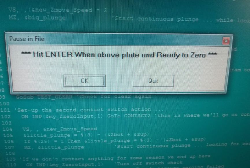
- Now calibrate the 0-point for the Z axes. Move the robot arm to a concenient place to set the Z-axis. Also choose a spot where your material is at its flattest, so you are sure you will be milling all the waythrough. Bring the robot arm down a bit. Press the Z-icon on the top of the screen. Then get the metal plate and touch the end mill with it to see if it gives a signal. When the green 'light' on the screen flashes, there is contact.
- Press OK and the robot arm will go down until it touches the metal plate. This will be set as zero.
- Now put in the earplugs, put on your glasses and make sure nothing is on the machine bed (tools and the like. Then turn on the mill with the key and press start. Keep your hand above the space bar in case anything goes wrong directly at the start. Also be aware of the sound the machine makes. If something changes and you don't trust it, stop the machine with the space bar.
- When the machine is done, turn the key again to stop it. Turn of the air exhaust. And close the software.
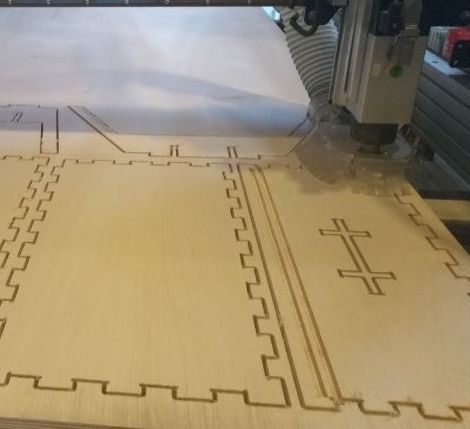
Disconnecting the parts, sanding and assembling
When the machine is off, you can remove your material. Unscrew it. Use a small saw to disconnect the tabs. Dispose small parts and store the bigger parts for reuse.
Now it is time to sand your parts. I used a P60 for the tabs and a P180 for the rest of the parts.
Ans then you assemble the parts. The slots should not be too tight, but also not too loose.
The result
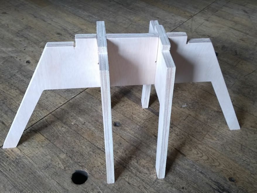
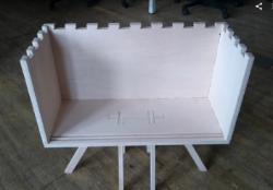
The result leaves room for improvement. First I have made the mistake of copying the bottom pannel, thinking that it was the same as the top panel. This turnes out not to be true. I am afraid I have to mill the top panel again. The second thing is that the slots are a bit to loose. For this design I will solve it with a bit of glue. If I re-mill the top panel, I will use a smaller offset, or maybe no offset at all, so that this part will firmly hold the back-and side panels.
Conclusions and learning outcomes
One of the remarks Frank made, when lecturing us on the theory of CNC was: Do not use the CNC when tired, hasty or grumpy. I am afraid I violated that rule. I was tired AND hasty At the beginning of this week I thought about making a very simple design. Just because I had some work left to do for last weeks assignment. But it felt wrong to settle for something easy, when I could make something beautiful and usefull. I though I had a good idea making a dressoir. There where two usefull tutorials for a stool and a press fit box, that I could combine. But I overestimated my skills with Fusion 360. And by the time I got to the lab, my design was half finished. I had spend the whole sunday on it and slept very bad that night. On top of that exporting to DXF just didn't work, so that took a lot of time. So I was hasty because I was using Henk's milling time and that made me make the wrong choices. For the future I really have to be less ambitious with my designs. There is a lot to learn anyway.