Week 9: Embedded programming
This weeks assignment
- Read a microcontroller datasheet.
- Program your board to do something, with as many different programming languages and programming environments as possible.
- Group assignment: Compare the performance and development workflows for other architectures
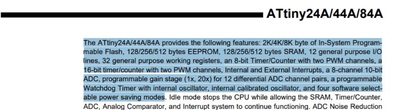
Reading the ATtiny 24A/44A/84A datasheet
The ATtiny 24A/44A/84A datasheetT is a 286 paged document. My strategy for 'reading' this datasheet will be as follows:
- See what other students did reading a microcontroller datasheet.
- Find out about voltage to use on the microcontroller and min/max temperatures.
- Try to understand the relation between internal clocks, communication and oscillators.
- Try to understand the Features described at the first page.
- Study the Pin Configurations and descriptions.
- Find information about PWM, ADC and pull up resitors , like we discussed with Emma on thursday.
What did other students do reading a microcontroller datasheet?
I studied a few websites of previous Fab Academy students. The sites of Marc Conangla, Joris Lam and Sander van Vliet where of particular use. Marc pointed my attention on the possibility of Capacitive Touch Sensing. Could this be interesting for my final project? From Joris I got the idea of finding out about internal clocks and oscill ators and their function in communication. Sanders approach was to search for information on terms he didn't understand and explain them briefly on his website. This is something I had in mind as well.
Voltage and min/max temperatures
On the first page, in the section of Features, I found information about operating voltage and min/max temperatures.
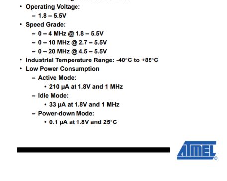
So, on this microcontroller I can apply 1,8 to 5,5V and I can use it at temperatures ranging from -40 to +85 degrees Celsius. The speed grade I don't understand completely. Probably it has to do with the calculation/executing speed I ask of it and what voltage will be needed for it. A higher speed demands a higher voltage, that makes sense.
The relation between internal clocks, oscillators and communication.When we downloaded the Arduino software last thursday, we had to change some settings in the Tools menu, one of which was "external clock 20 mHz". After this we had to burn the bootloader. It has something to do with the speed that comes with the program you send to the microcontroller and the speed at which the microcontroller operates. We had allready seen during the group assignment that a delay of 100 ms, became a delay of 850 ms in reality. The led was blinking slower than we had programmed. After we burned the bootloader, the delay matched up with the program.
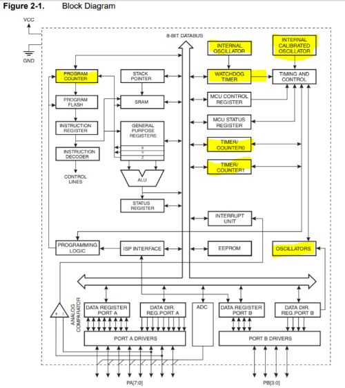
From this block diagram I think I see that a few subsytems have to do with matching the timing of the program with the timing of the microcontroller. I have marked them in yellow. On page five, I read the following:
What do 8 and 16- bit timer/counters do and why are they associated with PWM channels? What does the Watch Dog Timer do and what is the oscillator for? An answer to my first question I found here. From what I understand of it. If you want a LED to blink or to fade; you will have to tell the microcontroller at what interval it should blink of with what proportion it should fade. In the first case, it will use a timer to measure the interval and in the second case a counter to count the proportion of fading. An oscillator sets the beat of the counting. A clear description of what you need oscillators for in a microcontroller I found here. Now I understand why we set the clock to 20mHz in the Tools settings in the Arduino IDE software. It is because I soldered a 20MHz resonator to my board.
PWM stands for Pulse Width Modulation. This comes in handy when you want a voltage inbetween HIGH and LOW. This would be analog signal and for instance needed for fading a LED. A PWM channel modulates the pulse widht. For instance if the pulse is HIGH (5V) for 9 ms and LOW for 1 ms, the Voltage that is read in 4,5V = 90% of 5V. Now it makes sence that a PWM channel is associated with the timer/counters.
Understanding the FeaturesSo the first term to understand: RISC. It stands for Reduced Instruction Set Computer. Neils started his lecture with it on wednesday. RISC's are microprocessors that have less circuits then Complex Instruction Set Computers. They have a smaller instructionset. An instructionset is a collection of all possible machinecodes that a processor can handle. Because of the smaller instructionset, the RISC has to proces more instructions for the same task, then a CISC. This can be compensated by a higher calculation speed. I guess the 120 instructions is the instruction set for this MC and they can allmost all be excuted in a single clock cycle.
And what might be the General Purpose Working Registers mentioned in Features? From the website of worldofcomputing I learned that a register is a memory. Citing: "It consists of a set of binary storage cells called flip-flops with parallel reading or writing or both the facilities. Register plays a major role in CPU operations. Microprocessor picks up data from one of the registers for doing arithmetic or logical operation. Once the operation is over, it stores the result in a register. Data are usually loaded from memory to register. Similarly the resultant data will be loaded from registers to memory." End of citation.
Fully Static Operationmeans that your program isn't lost when you unplug it. The memory cells stay in their 0 or 1 state even without voltage.
Pin configurationsThe Pin configuration of the ATtiny44a looks like this.
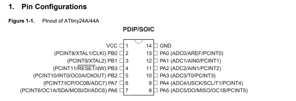
I don't understand the difference between the A and B pins yet. It seems that the only difference is 8 vs 4 bit respectively.And the A-pins have a ADC connected, so they can handle analog signals??
Programming the Hello_Echo Board
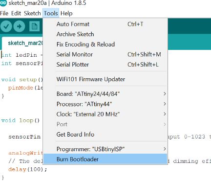
The first things to do when you try to program a ATtiny board with the Arduino IDE software, you have to change some settings in the Tools menu. And when you have done that, click 'burn bootloader'. Check out the picture below.
On wednesday we tried some simple Arduino programs to get familiar with the Arduino programming language and learn to adjust them for our Hello_Echo Board. I will start to repeat the a few of them just to refresh my knowledge and also for documentations sake.
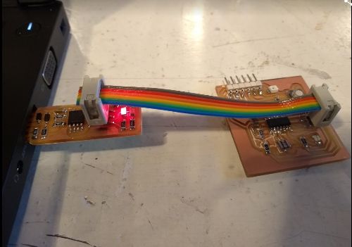
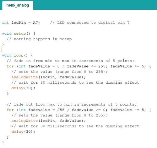
So, I attached my programmer to my Hello_Echo Board and put the programmer into the USB-port. I opened Arduino and from Files and Sketchbook, I chose the Hello_Analog program. This program fades the led using the analogWrite function. First I have to check what pin my LED is on, because the program in Arduino assumes I am using a ATmega328P. (The Arduino UNO has that kind of microcontroller.) I used the schematic lay out of week 7 to check what pin is connected to what component on the board. The LED is connected to pin 7, the button is connected to pin 3 and the phototransistor is connected to pin 2.
In the Hello_Analog program I changed the LED pin from 9 to 7, verified the code and uploaded it to my board. It worked.
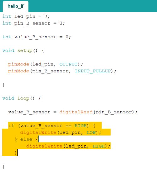
In this way I also tried the programs 'Hello analog simple' and ' Hello digital', changing the pin numbers to the corresponding ATtiny44 pins. A special note for the program Hello_if. This code denominates the sensor to pin 3. that would be the button on my board. So if I press the button the LED should go on. I type input pullup to initiate the pull up resistor in the microcontroller, because I would otherwise connect VCC to ground directly. One thing that can be confusing in this code, is that is says:
if (value_B_sensor == HIGH) {digitalWrite(led_pin, LOW);} else {digitalWrite(led_pin, HIGH);}
Intuitively you might think that if the button is pressed, the voltage is HIGH. But actually pin 3 is measuring voltage between the button and VCC. So if the button is off, it measures 5V (HIGH) and when it is pressed, it measures 0V (LOW).
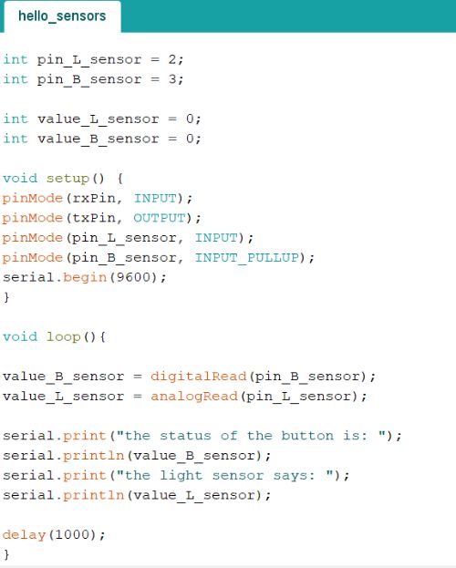
Hello_Sensors: Problems with COM4
In the hello_sensors program, your board should talk back to your computer. For this you need FTDI drivers. I used this guide to install them. The strange thing is, my laptop will not show the USB serial port and the USB serial converter like it should according to the manual.
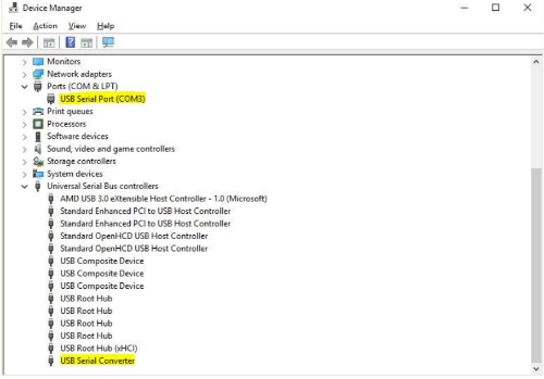
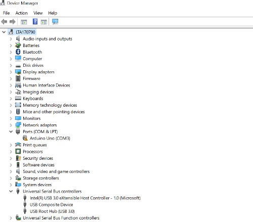
When I upload the hello_sensor program and open the serial monitor, I get the message: "Board at COM4 is not available". I have tried to manually install the drivers, that didnt' help. I've looked up the files in the folder C:\Windows\System32\DriverStore\FileRepository\ftdiport.inf_amd64_90039b7dbf236588 and right click the .inf file and click 'install' but that didn't work. I also tried: Device Manager -Actions-Add legacy hardware-Install the hardware that I manually select from a list and then select the .inf file. But none of this made the USB serial Port or the USB Serial Converter appear in my Device Manager.
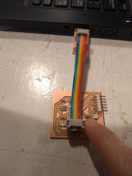
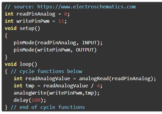
Light on, LED off
I looked on the internet for a code that would dim the LED with higher light intensity. I found a code here. When I changed the pins acording to my board, verified and uploaded the program, the LED would not respond to the flashlight on my phone. I couldn't understand why. I though maybe it was because I am using a phototransitor instead of a photoresistor. The code is for a photoresistor. I looked on the internet to find the difference between the two. A photoresistor lowers resistance in reaction to higher light intensity, a phototransitor increases current in reaction to higher light intensity. The result should be the same. I tried dividing by 8 or by 16 instead of 4 in the code, thinking maybe there is another ratio between the phototransitor and the LED in my board, then the components the Arduino uses. It still did not work.
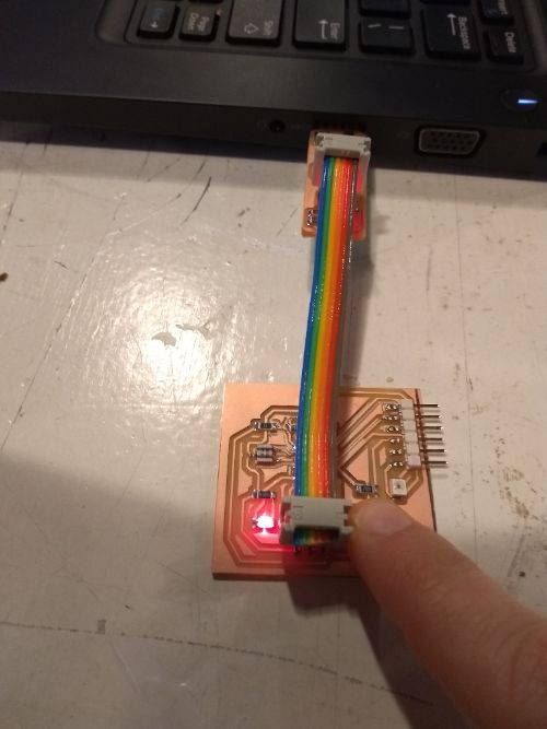
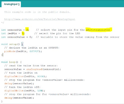
Then I tried the AnalogInput program in the examples that come with the Arduino IDE software. I changed the pins according to my board, verified and uploaded the program. It worked. What I noticed, that it is not very sensitive. It needs a lot of light to respond. Maybe this was the problem with the other program, I thought. So I uploaded the previous program again and this time I held the flashlight really close to the phototransitor. And it did work! Finally I erased the division by 4 alltogether to make it more sensitive and that worked as well.
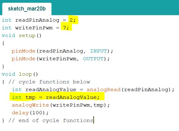

Underneath here are the codes I used and adjusted for my board. The explaination of the different command lines is in the code itself.
Code phototransitor controlling LED