changes:
Board:
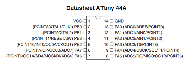
im using Echo ftdi board designed in week-6 .. in the design i flipped the pins (tx , rx) as i needed to connect the traces without jumpers so here, the first thing i would do is to change the code of sending pin (tx) with the recieving pin (rx)
in the code its defined as preprocessor:
    //#define serial_pin_in (1 << PA0)
    //#define serial_pin_out (1 << PA1)
    #define serial_pin_in (1 << PA1)
    #define serial_pin_out (1 << PA0)
new line:
im sending now with the CR+LF for windows new line compatible
buffer storage:
the other problem can be seen in previous video in week 6 i’ve edited the buffer storage functionality… where now i check that i dont go above the array size and to reset when ENTER is sent. (probably the code was intended to do somthing else??)
UPLOAD:
CODE:
//
//
// hello.ftdi.44.echo.interrupt.c
//
// 115200 baud FTDI character echo, interrupt version
//
// set lfuse to 0x5E for 20 MHz xtal
//
// Neil Gershenfeld
// 12/8/10
//
// (c) Massachusetts Institute of Technology 2010
// This work may be reproduced, modified, distributed,
// performed, and displayed for any purpose. Copyright is
// retained and must be preserved. The work is provided
// as is; no warranty is provided, and users accept all
// liability.
//

#include <avr/io.h>
#include <util/delay.h >
#include <avr/interrupt.h >
#include <avr/pgmspace.h >

#define output(directions,pin) (directions |= pin) // set port direction for output
#define set(port,pin) (port |= pin) // set port pin
#define clear(port,pin) (port &= (~pin)) // clear port pin
#define pin_test(pins,pin) (pins & pin) // test for port pin
#define bit_test(byte,bit) (byte & (1 << bit)) // test for bit set
#define bit_delay_time 8.5 // bit delay for 115200 with overhead
#define bit_delay() _delay_us(bit_delay_time) // RS232 bit delay
#define half_bit_delay() _delay_us(bit_delay_time/2) // RS232 half bit delay
#define char_delay() _delay_ms(10) // char delay

#define serial_port PORTA
#define serial_direction DDRA
#define serial_pins PINA
//#define serial_pin_in (1 << PA0)
//#define serial_pin_out (1 << PA1)
#define serial_pin_in (1 << PA1)
#define serial_pin_out (1 << PA0)

#define serial_interrupt (1 << PCIE0)
//#define serial_interrupt_pin (1 << PCINT0)
#define serial_interrupt_pin (1 << PCINT1)
#define max_buffer 25

void get_char(volatile unsigned char *pins, unsigned char pin, char *rxbyte) {
   //
   // read character into rxbyte on pins pin
   //    assumes line driver (inverts bits)
   //
   *rxbyte = 0;
   while (pin_test(*pins,pin))
      //
      // wait for start bit
      //
      ;
   //
   // delay to middle of first data bit
   //
   half_bit_delay();
   bit_delay();
   //
   // unrolled loop to read data bits
   //
   if pin_test(*pins,pin)
      *rxbyte |= (1 << 0);
   else
      *rxbyte |= (0 << 0);
   bit_delay();
   if pin_test(*pins,pin)
      *rxbyte |= (1 << 1);
   else
      *rxbyte |= (0 << 1);
   bit_delay();
   if pin_test(*pins,pin)
      *rxbyte |= (1 << 2);
   else
      *rxbyte |= (0 << 2);
   bit_delay();
   if pin_test(*pins,pin)
      *rxbyte |= (1 << 3);
   else
      *rxbyte |= (0 << 3);
   bit_delay();
   if pin_test(*pins,pin)
      *rxbyte |= (1 << 4);
   else
      *rxbyte |= (0 << 4);
   bit_delay();
   if pin_test(*pins,pin)
      *rxbyte |= (1 << 5);
   else
      *rxbyte |= (0 << 5);
   bit_delay();
   if pin_test(*pins,pin)
      *rxbyte |= (1 << 6);
   else
      *rxbyte |= (0 << 6);
   bit_delay();
   if pin_test(*pins,pin)
      *rxbyte |= (1 << 7);
   else
      *rxbyte |= (0 << 7);
   //
   // wait for stop bit
   //
   bit_delay();
   half_bit_delay();
   }

void put_char(volatile unsigned char *port, unsigned char pin, char txchar) {
   //
   // send character in txchar on port pin
   //    assumes line driver (inverts bits)
   //
   // start bit
   //
   clear(*port,pin);
   bit_delay();
   //
   // unrolled loop to write data bits
   //
   if bit_test(txchar,0)
      set(*port,pin);
   else
      clear(*port,pin);
   bit_delay();
   if bit_test(txchar,1)
      set(*port,pin);
   else
      clear(*port,pin);
   bit_delay();
   if bit_test(txchar,2)
      set(*port,pin);
   else
      clear(*port,pin);
   bit_delay();
   if bit_test(txchar,3)
      set(*port,pin);
   else
      clear(*port,pin);
   bit_delay();
   if bit_test(txchar,4)
      set(*port,pin);
   else
      clear(*port,pin);
   bit_delay();
   if bit_test(txchar,5)
      set(*port,pin);
   else
      clear(*port,pin);
   bit_delay();
   if bit_test(txchar,6)
      set(*port,pin);
   else
      clear(*port,pin);
   bit_delay();
   if bit_test(txchar,7)
      set(*port,pin);
   else
      clear(*port,pin);
   bit_delay();
   //
   // stop bit
   //
   set(*port,pin);
   bit_delay();
   }

void put_string(volatile unsigned char *port, unsigned char pin, char *str) {
   //
   // print a null-terminated string
   //
   int index1;
   index1 = 0;
   do {
      put_char(port, pin, str[index1]);
      ++index1;
      } while (str[index1] != 0);
   }

ISR(PCINT0_vect) {
   //
   // pin change interrupt handler
   //
   char chr;
   static char buffer[max_buffer];
   static int index;
   get_char(&serial_pins, serial_pin_in, &chr);
   put_string(&serial_port, serial_pin_out, "interrupt: \"");
   if (chr != 10 && chr != 13)
    buffer[index++] = chr;
   if (index == (max_buffer-1))
      index = 0;
   put_string(&serial_port, serial_pin_out, buffer);
   //if (chr != 10 && chr != 13)
   //put_char(&serial_port, serial_pin_out, chr);
   put_char(&serial_port, serial_pin_out, '\"');
   put_char(&serial_port, serial_pin_out, 10); // Carriage Return
   put_char(&serial_port, serial_pin_out, 13); // line feed for putty and windows
   }

int main(void) {
   //
   // main
   //
   // set clock divider to /1
   //
   CLKPR = (1 << CLKPCE);
   CLKPR = (0 << CLKPS3) | (0 << CLKPS2) | (0 << CLKPS1) | (0 << CLKPS0);
   //
   // initialize output pins
   //
   set(serial_port, serial_pin_out);
   output(serial_direction, serial_pin_out);
   //
   // set up pin change interrupt on input pin
   //
   set(GIMSK, serial_interrupt);
   set (PCMSK0, serial_interrupt_pin);
   sei();
   //
   // main loop
   //
   while (1) {
      //
      // wait for interrupt
      //
      ;
      }
   }
Timer/counter
Note: im using Atmega328 for this post with 8 bit timer:
datasheet
before i start, this post shows simple blink program .. i will try to describe how timer/counter
believe me, if you really want to understand it .. the best is to read full datasheet and watch some
avr geeks’ tutorial …
for me, i dont know all the features in timers, i will describe simple blink program .. not pwm or somthing just an ISR function (inturrept service routine) ..
what is ISR
to make it simple, and ISR function, is a function that interrupt your code and goes to some function that is predifined.. in microcontroller that has no OS (operating system) .. an ISR function is predefined in the processer through somthing calledNVIC (Nested Vectored Interrupt Controller)
but what is NVIC
if you are so intrested to know all these details, i would suggest you to read more about C, assembly, well and this video describe NVIC pretty good https://www.youtube.com/watch?v=uFBNf7F3l60&t=833sOK, lets start
What is the Prescaler:
The prescaler is electronics counting circuit that reduces high frequency to lower one by integer division. the prescaler is just a clock divider When you set Prescaler to 8 and you have 8MHz clock. You will get output 1MHz from the prescalertimer/counter [TCNT]:
This register that holds the count value from timer ticks (after applying prescaler)ok, this is getting boring, lets see the code then we will continue ..
#define F_CPU 16000000UL

#include <avr/interrupt.h>
#include <avr/io.h>
#include <util/delay.h>

volatile static uint8_t x = 1;


ISR( TIMER0_COMPA_vect)
{
    x++;
    if (x == 100) // 100* 10ms = 1000 ms
    {
        PORTB ^= 0B00100000;
        x=0;
    }
}

int main(void)
{

    //Set Direction port B to output pin 13 in arduino
    DDRB = DDRB | 0B00100000 ;
    //Timer/counter control register A
    TCCR0A = 0;
    TCCR0A |= 1<< WGM01; // CTC mode - clear counter when reaches to OCR0A

    //Timer/counter control register B ->  clk select bits:
    TCCR0B = (1 << CS00 ) | (1 << CS02 );  //1024 prescaler = 15625 ticks / sec @ 16MHz

    //output compare A
    OCR0A = 156;  //  156 * (1/15625) = 9.984ms
    // interrupt mask register
    //TIMSK0 |= 1 << TOIE0 ; // [TOIE0] interrupt enable bit = 1
    TIMSK0 |= 1<< OCIE0A; // [output compare A interrupt enable 0]

    sei();

    while (1)
    {
     // you can do anything here.. the mcu will blink 1 sec ...

    }
}
lets start with the code in the main function:
Input output programming:
- DDRB this is simple the data direction port sets port B ..
- PORTB here you set the pin to be high or low .. when its configured as output..
read more about digital Input output programming
Timer Stuff:
TCCR0A this is called Timer/counter Control Register i set the WGM bit to CTC mode ..
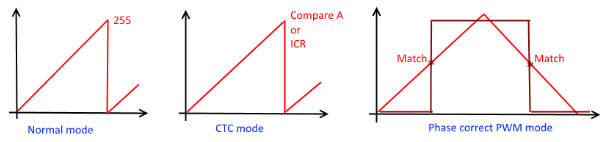 in CTC mode, you can set a value and when the timer reach to it.. it will reset the timer .. this give you better control ..
CTC: Clear timer on compare match
in CTC mode, you can set a value and when the timer reach to it.. it will reset the timer .. this give you better control ..
CTC: Clear timer on compare matchTCCR0B this is still timer/counter control register .. but this is the second register im setting up CS bits (clock select):
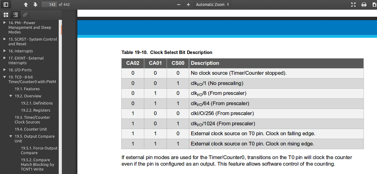
1024 prescaler = 15625 ticks / sec @ 16MHz:
the microcontroller is running with 16 MHz system clock which means
there are 16,000,000 ticks in a second ..
setting the timer prescaler to 1024 means the timer will have
16,000,000 / 1024 = 15625 ticks/sec
- OCR0A output compare register
when the counter reaches to the value in this register, it will trigger the compare interrupt ISR and will reset the counter..
- TIMSK0 timer mask
i just set the on compare enable interrupt bit here..
which means that when the timer counter register [TCNT] reaches to the Compare A register [OCR0A] it will trigger special ISR function ..
result:
although the code was and first implementation was done on arduino uno “atmega328”, you can see the datasheet discreption and screenshots are on atmega328
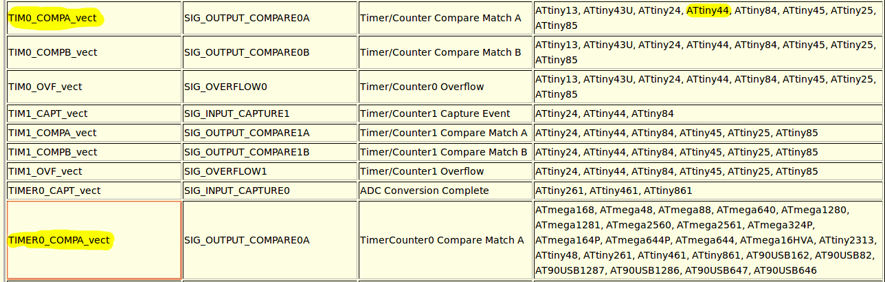
however, the same timer exist in attiny44, here is a good link for avr-libc “inturrept ISRs”:
Avr-libc: <avr/interuupt.h>
the change in code is the ISR function name:
- Code:
#define F_CPU 20000000UL

#include <avr/interrupt.h>
#include <avr/io.h>
#include <util/delay.h>

volatile static uint8_t x = 1;


ISR( TIM0_COMPA_vect )
{
    x++;
    if (x == 100) // 100* 10ms = 1000 ms
    {
        PORTB ^= 1<<2; //led on io board
        x=0;
    }
}

int main(void)
{
    // CLOCK prescaler to /1
     CLKPR = (1 << CLKPCE);
     CLKPR = (0 << CLKPS3) | (0 << CLKPS2) | (0 << CLKPS1) | (0 << CLKPS0);
    //Set Direction port B to output pin 13 in arduino
    DDRB = DDRB | 1<<2 ; //led on IO board
    //Timer/counter control register A
    TCCR0A = 0;
    TCCR0A |= 1<< WGM01; // CTC mode - clear counter when reaches to OCR0A

    //Timer/counter control register B ->  clk select bits:
    TCCR0B = (1 << CS00 ) | (1 << CS02 );  //1024 prescaler = 15625 ticks / sec @ 16MHz
    //19531.25 ticks / sec @ 20MHz

    //output compare A
    //OCR0A = 156;  //  156 * (1/15625) = 9.984ms //for atmega328 16mhz
    OCR0A = 195; //195 / 19531 = 9.984ms //for attiny44 20mhz
    // interrupt mask register
    TIMSK0 |= 1<< OCIE0A; // [output compare A interrupt enable 0]

    sei();

    while (1)
    {
     // you can do anything here.. the mcu will blink 1 sec ...

    }
}
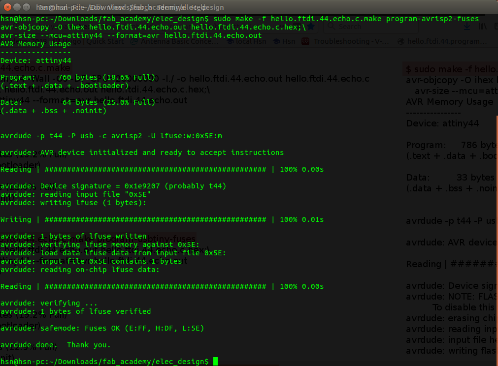
Compile:
avr-gcc -Wall -g -Os -mmcu=attiny44 -o x.bin x.c
avr-objcopy -O ihex x.bin main.hex
Flash:
avrdude -F -p t44 -P usb -c avrisp2 -U flash:w:main.hex
avrdude -F -p t44 -P usb -c avrisp2 -U lfuse:w:0x5E:m
So, what all this is about
this is just demostration of how 8-bit timer/counter in a microcontroller works,how to schudule a function with time control ..
if you get intreseted, i would suggest to read the datasheet it teaches a lot of things ..
good tutorials:
i didnt read them, but went through them very fast i think they really explain better than this post: