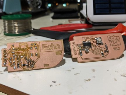
i’ve created new post because i needed another clean page to include the final pcb of this this week
please check the design work flow page
Schematic Design:
this is the schematic design:
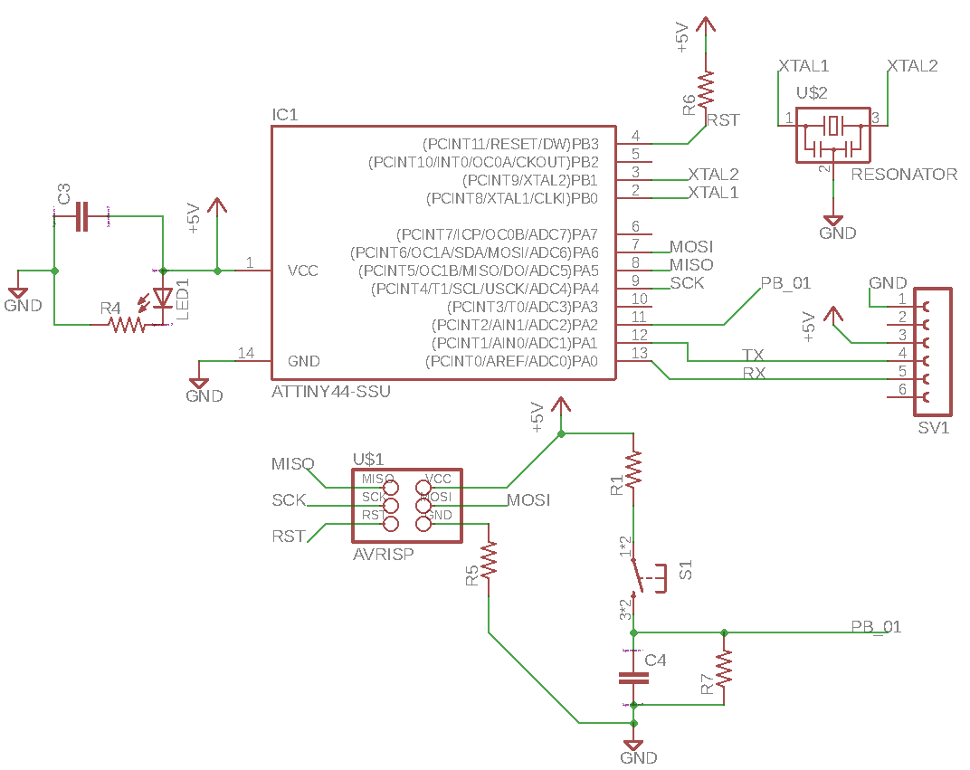
Component Selection:
- MCU attiny44
Resistors:
R1this resistor will control the charging speed of the
capacitorC4-> 10K OhmR4this resistor will limit current to prevent LED rush current:
minimum 330 Ohm5v - 1v(accros led) / 330 ohm < 12 mA
R50ohm just jumperR6pullup resistor, this drive the reset high to prevent mcu from reseting
and limit the current when the programmer short it to ground…R7to control the discharge ofC4when the button unreleased this resistor
provide path to discharge capacitor, 10k OhmC4this capacitor will charge and discharge when the button (pressed/released)
100nF
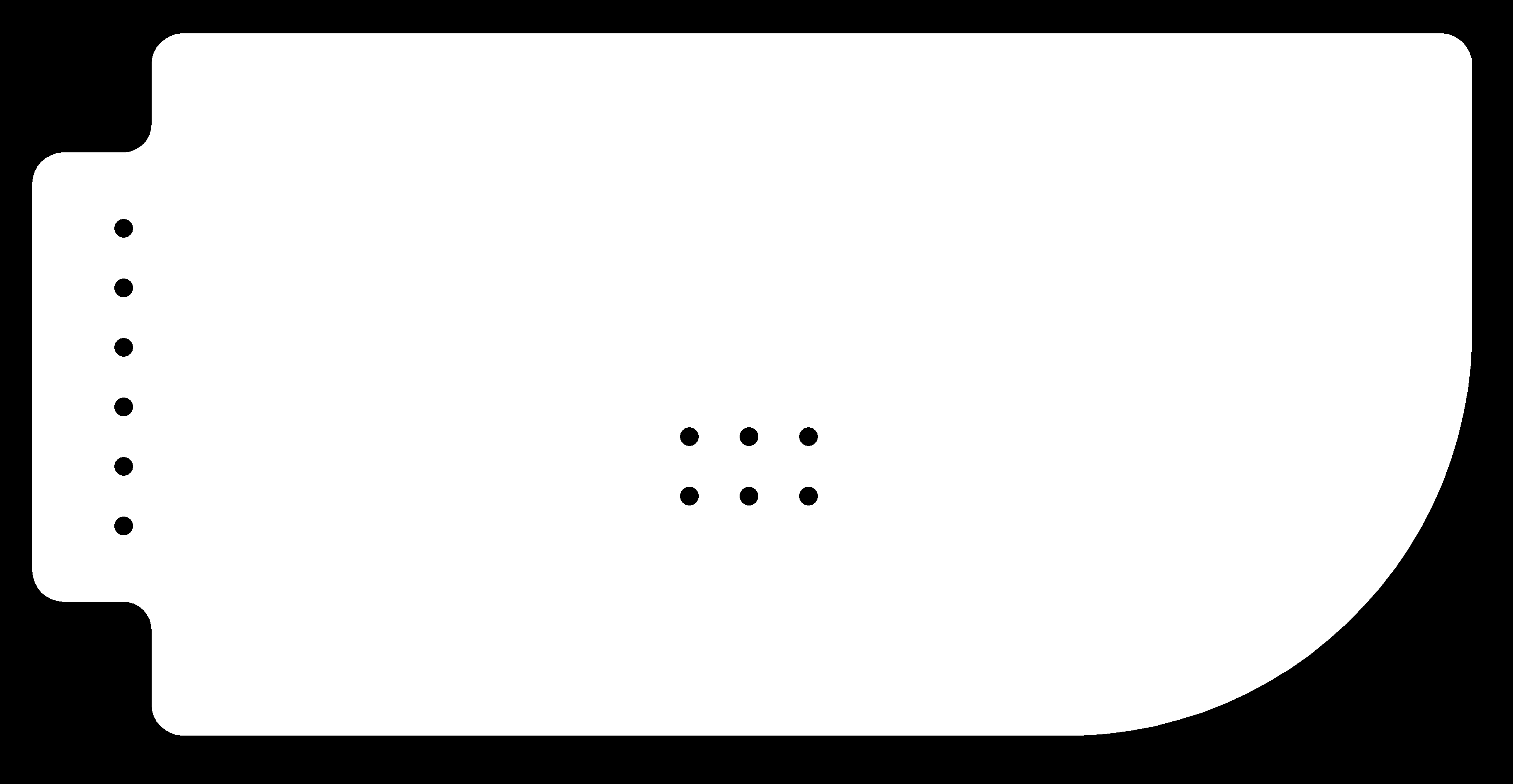
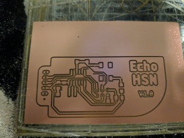
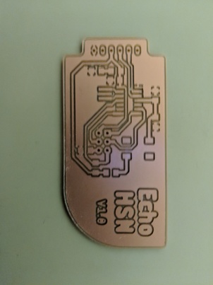
Pcb design:
this is the final pcb .. for technical details you can view the
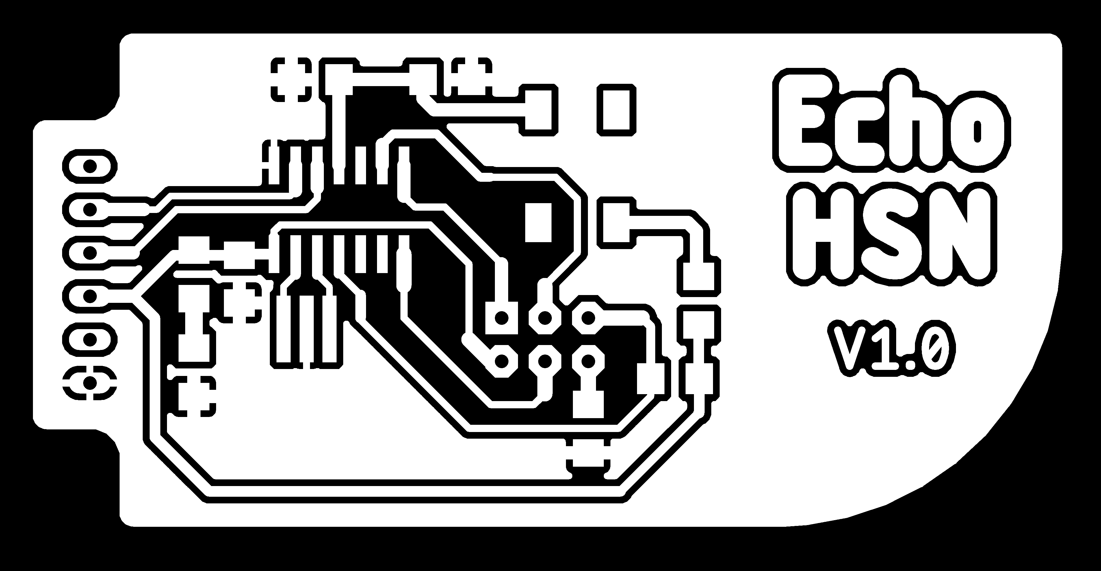
Design Considerations and tips
#design-considerations-and-tips
v1 tx - rx
v1 programming