i try to build a drawer that is inside a box with locking mechanism.. using Shopbot CNC for milling MDF wood.
design parameters:
im using shopbot CNC with the following materials:
- 1⁄4” drill bit (~6.4 mm)
- 12mm MDF wood plate
design limitation:
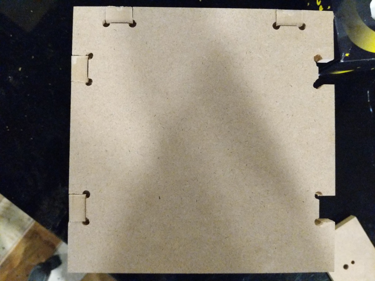
to start with i’ve used the following joints in the design:
dog bone
the dogbone is used in CNC because the drill-bit is round and cant make Inside straight corners.
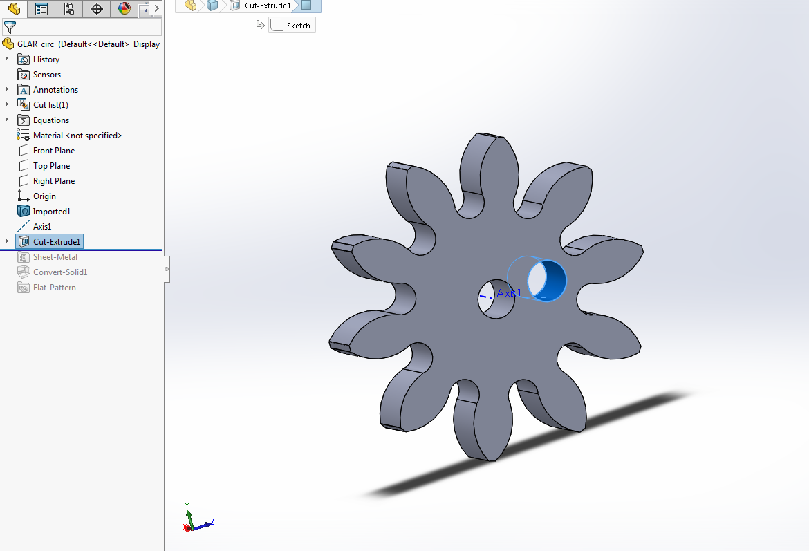
designing gears
gears are big subject i will briefly talk about the design here you can search about any gears tutorial im using solidworks add-in to place the gear. you can access it through the right panel:
- make an assembly: file-> new -> assembly
- right panel -> tool box -> ANSI Metric -> Power Transmission -> Gears -> Spur Gear
- then i put the parameters for the gear (module and number of teeth)
- save file as STEP
- open it again as part and modify
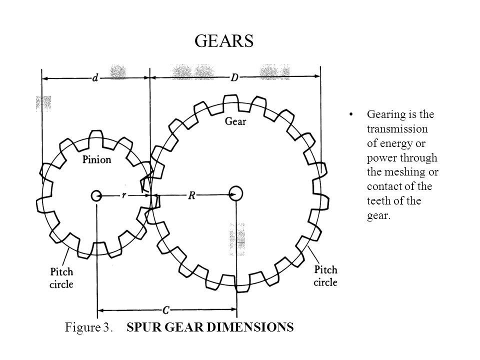
important parameters for gear:
im not mechanical engineer and i’ve very little knowledge but these are the parameters that i found important
- model (both gears have to be same Model - M)
- pitch circle: (the two circle of two gears must touch to transmit the power)
- number of teeth
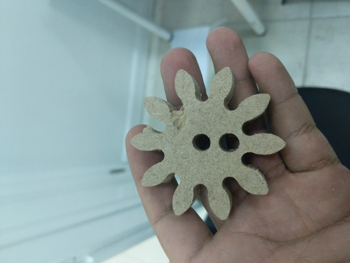
for the CNC it has to drill the gears with 1⁄4” drill bit, i’ve to set the smallest inner area to be exactly same as the drill-bit.
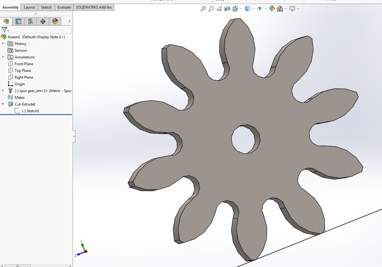
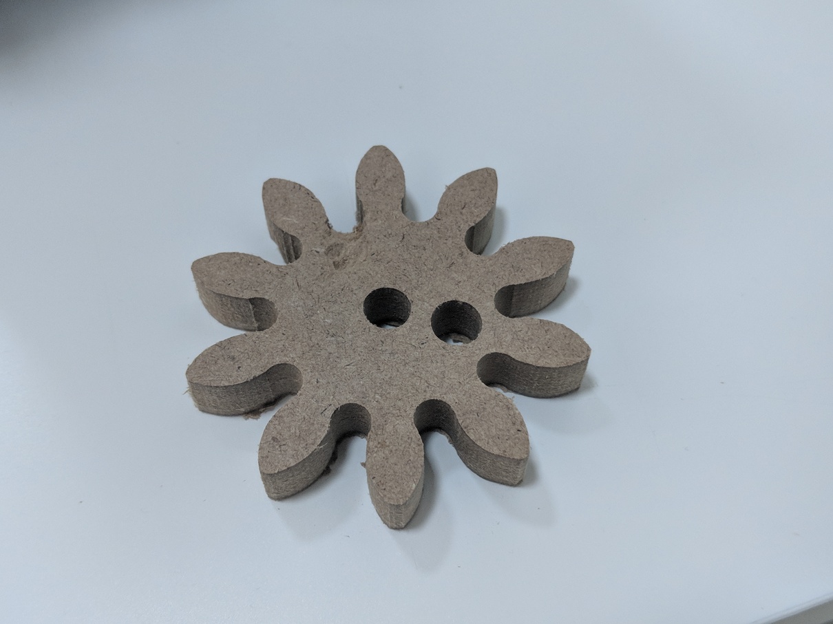
the gear selected was:
- module: 5.5
- teeth number: 10
- hence the base diameter: M x T = 5.5 * 10 = 55
distance in arc:
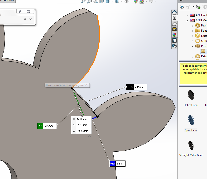
now the arc distance is larger than drill-bit so i can make this as hole in the cnc..
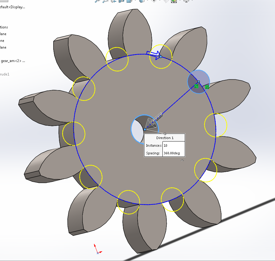
gears distance:
the gear distance are larger than base which of course have backlash and inaccuracy this is beacause im using them as bevel gear while they are just spur gears
 C = r+R
for me im going to use it as bevel gear although its not.. so i put more distance to avoid problems ..
yes it does gives inaccuracy and backlash
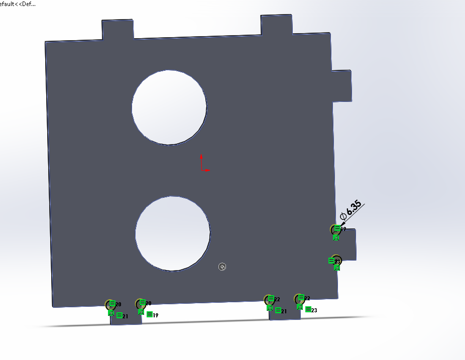
Design:
it really takes too much time to document all the design however i found the gear is the most one that is important to document so i did
here are some pictures of the design you can download it here Download
Shopbot:
the shop-bot software accepts DXF files which i exported all the parts in one file i set layers for different depths:
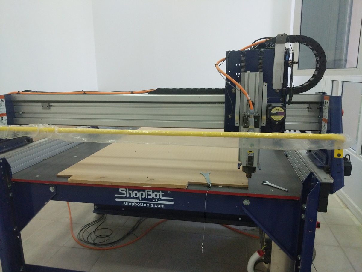
fixing the mdf plate to the workarea..
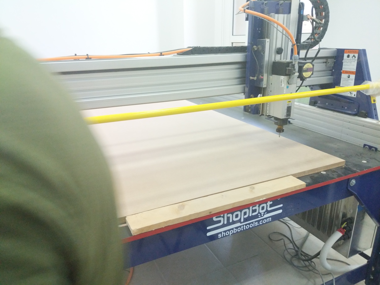
Zero (homing .. and running) ..
the cut parts ..
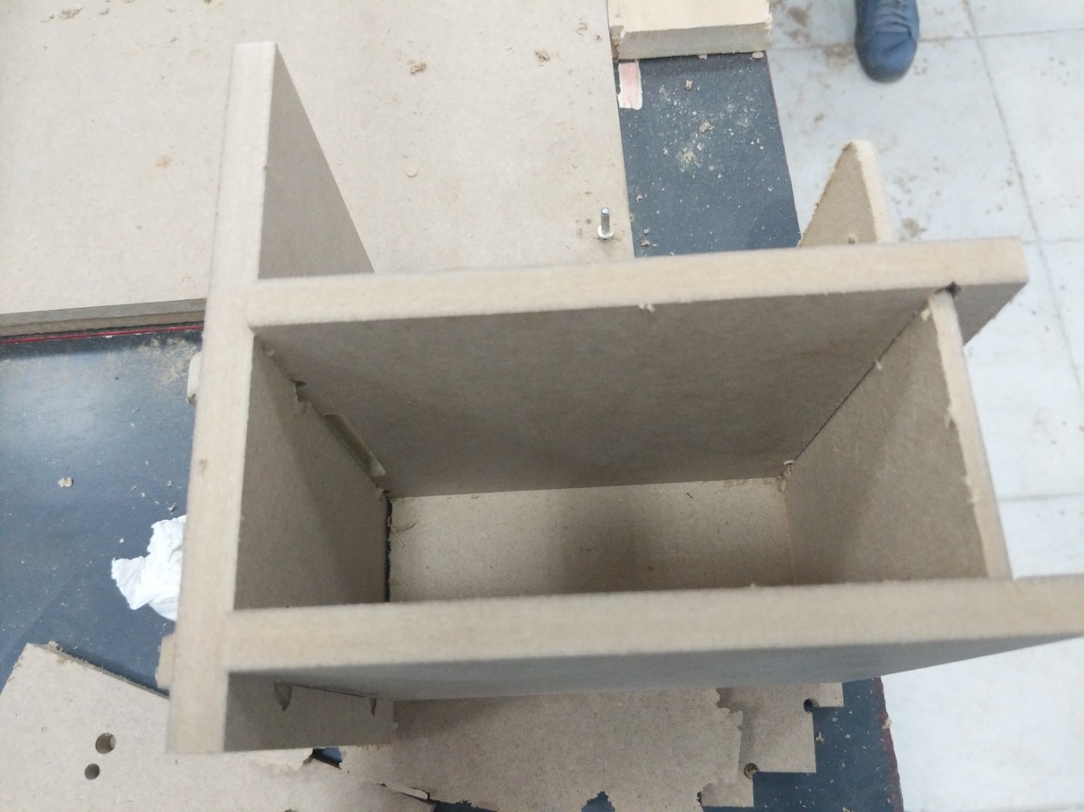
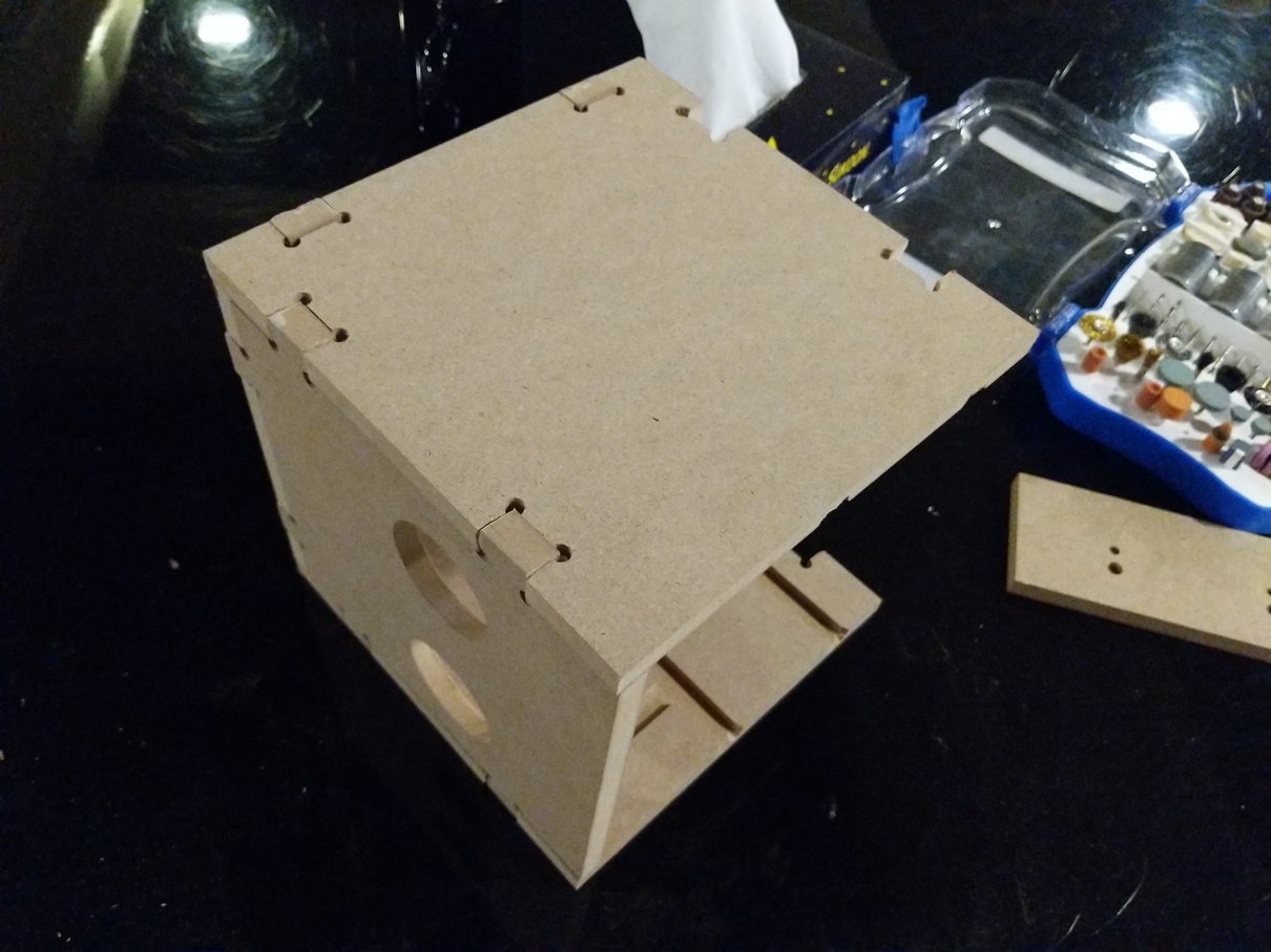
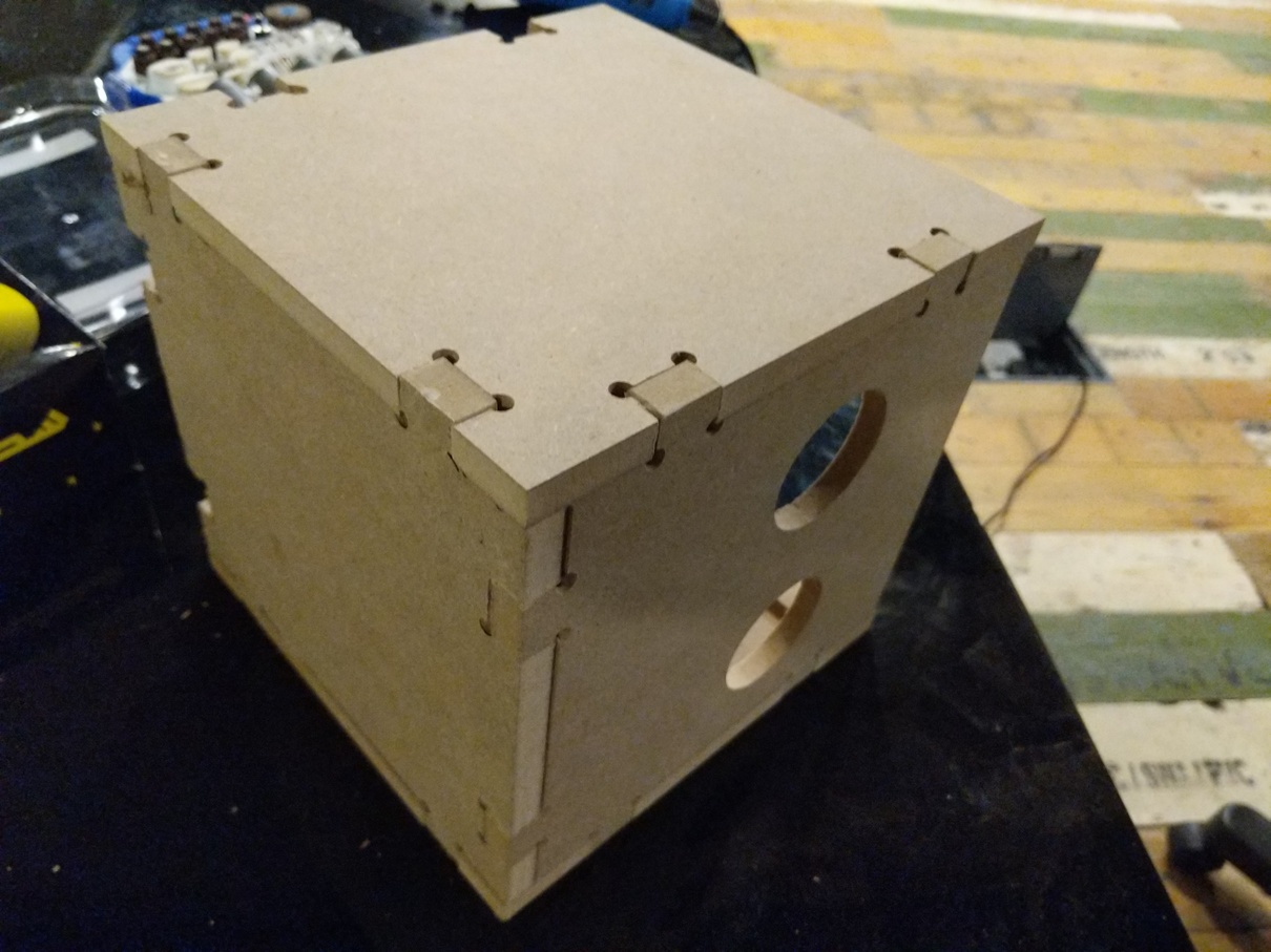
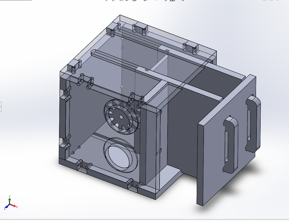
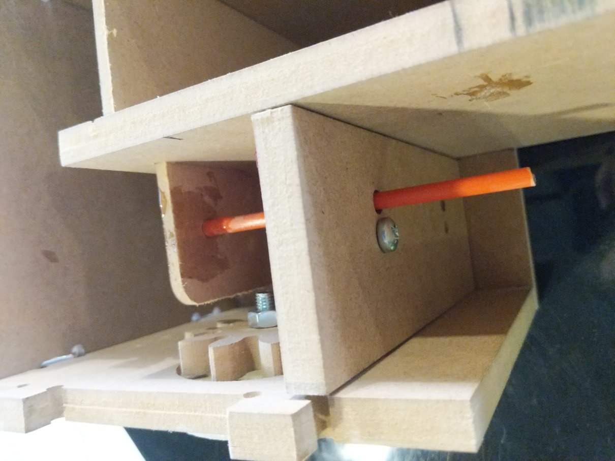
Assembly:
i assambled the box to Test gear motion:
i really didnt take care of shaft holding in the design and i had mistakes:
Design issues:
- fit joints: the joints were to tight that i have to press the parts hard which can damage them .. so most of joints were filed manually filed later
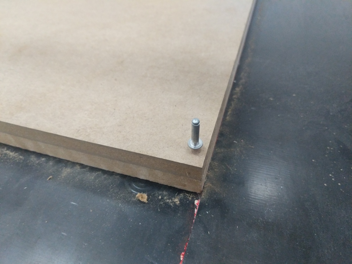
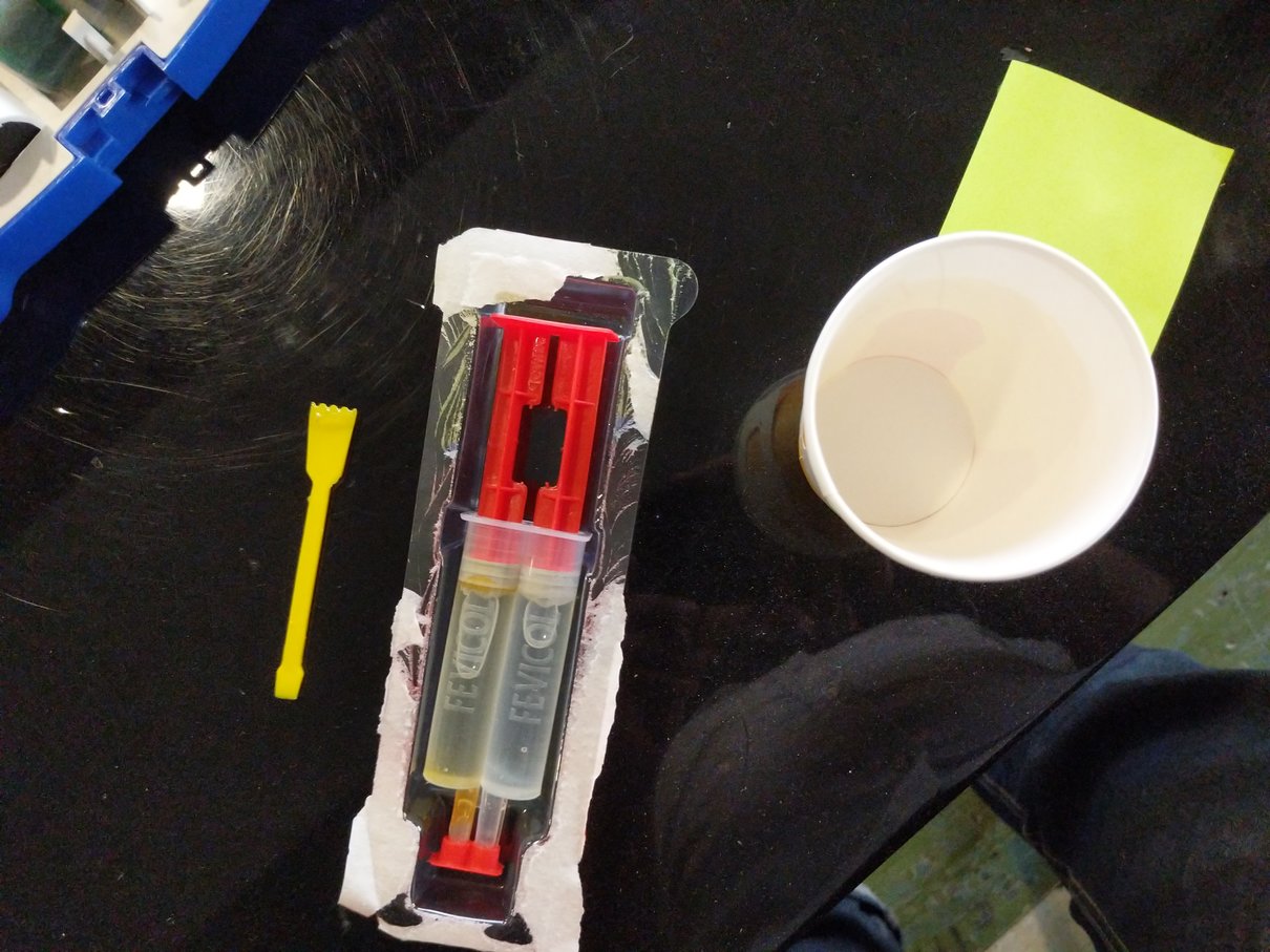
- pin holding: the pin holding is not properly designed so i sticked a 6mm shaft with a glue
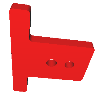
- pin alignment: this is really bad design where i should put the lock-gear to be behind the gear holder so the pin is holded from two sides .. to solve this issue a new 3d printed pin holder was designed and mounted near the locking gear.
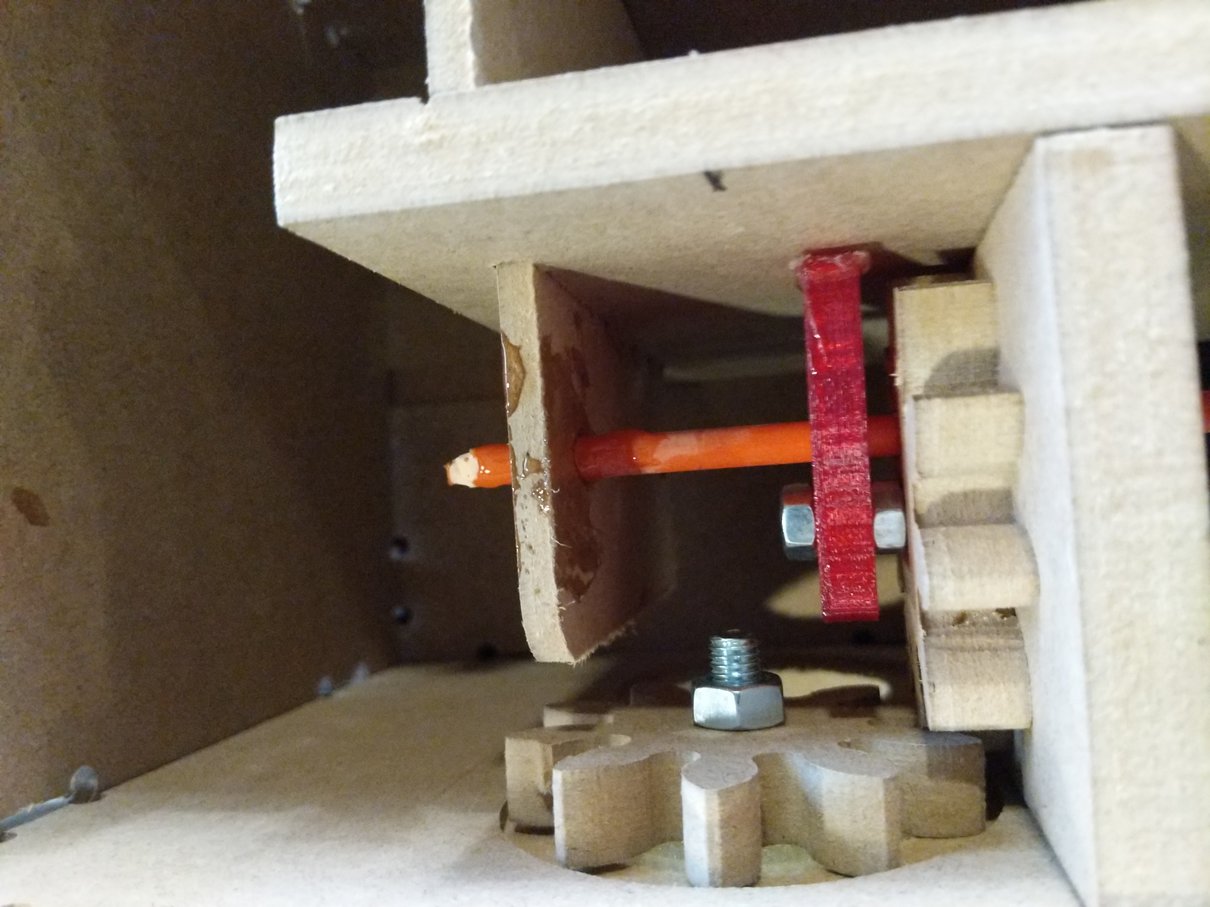
Result:
didnt complete it, another shaft i’ve to work on.. but im illustrating the mechanism here:
References:
cnc joint:
1. press-fit desk
2. creating cnc dog bone
3. cnc cut wood joints