Servo Bionic Butterfly

Final project

0.Introduction:

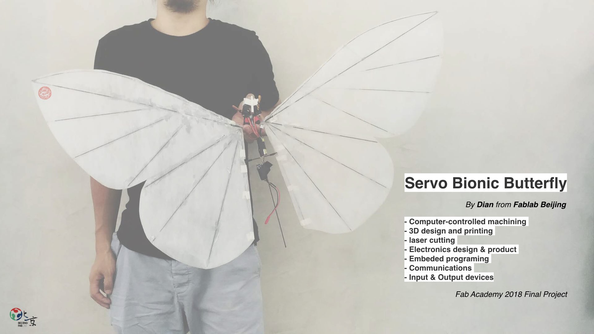
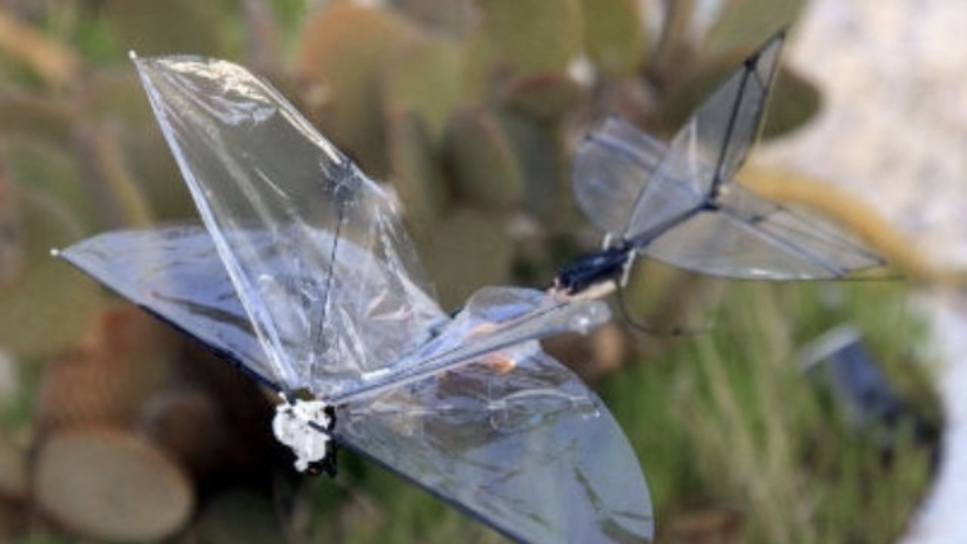
(What will it do?)
I am going to make a bionic butterfly that can fly in a windless indoor environment and control it to turn right and left through a 2.4G wireless remote control.
The reason I want to make this is a friend of my who working in a advertising company came to me and said whether I could make a mechanical butterfly like this.
The conditions are very attractive: Someone will help me to develop this project together with some financial support.
At the time, I was distressed about what my Final project was supposed to do. So when I heard this offer, I immediately agreed.

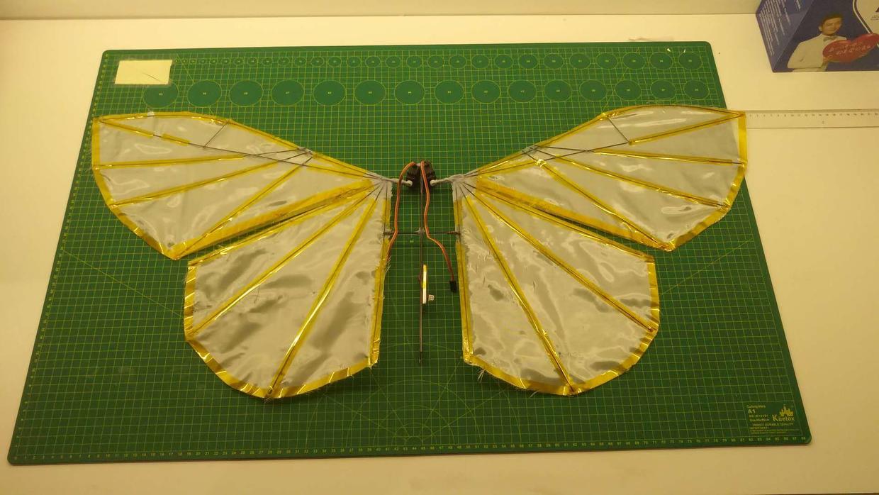
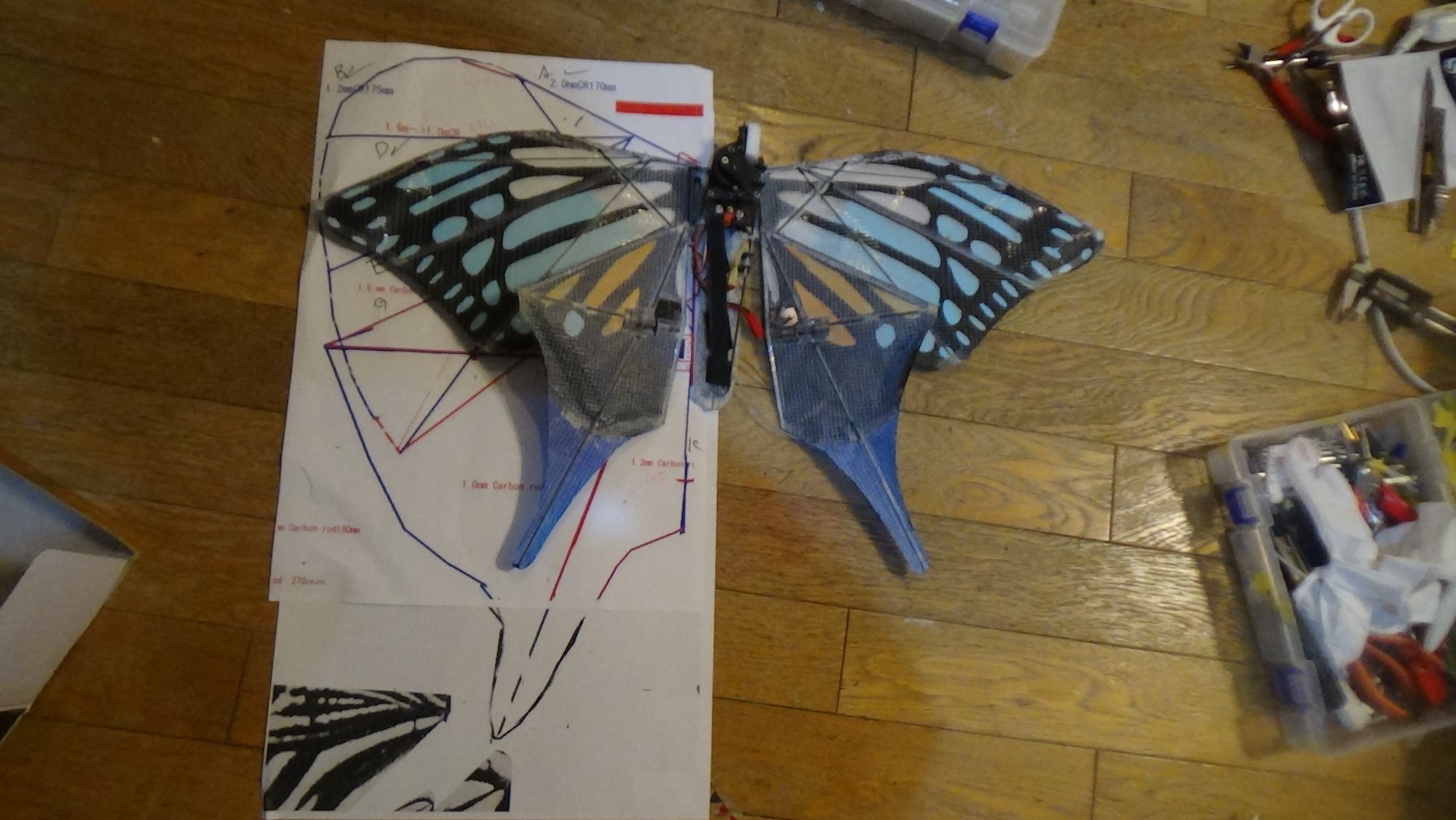
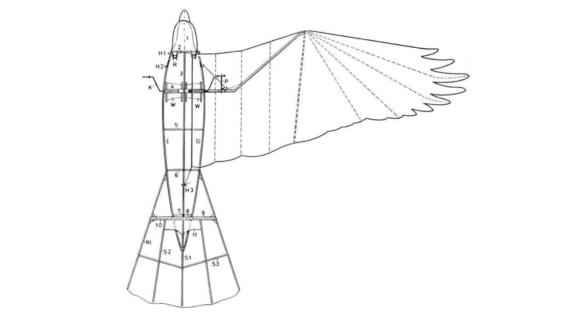
(What will you design?)
I decided to use carbon fiber as skeleton and structure, Arduino and 2.4g module as controller and communication part. I simply drew a sketch as follows

List

(What processes will be used?)

  • Computer-controlled machining
  • 3D design and printing
  • laser cutting
  • Electronics design & product
  • Embeded programing
  • Communications
  • Input & Output devices

  • (What materials and components will be used?)

  • Servo: KST MS320
  • 2mm & 1mm thick carbon fiber rod
  • Arduino uno mini
  • 2.4g modle
  • Kite paper
  • 300 mAh battery
  • 2mm acrylic plate
  • wires

  • (Where will come from?)
    All materials and components from Taobao
    (How much will they cost?)
    Totally cost around 300$
    Ps: Servo about 100$ for each

    1.Research

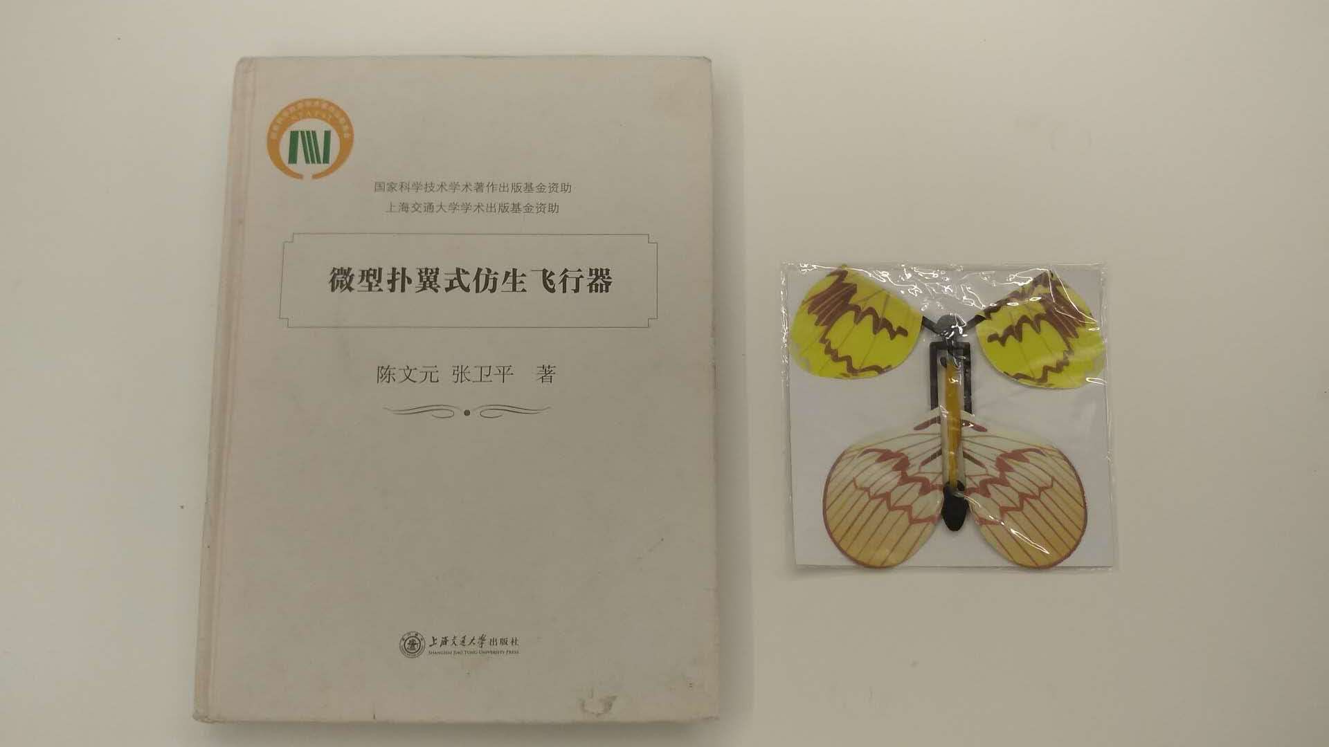
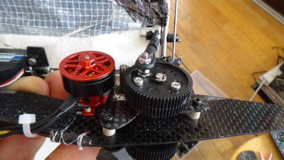
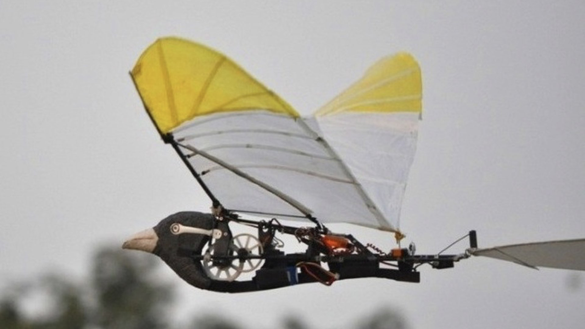
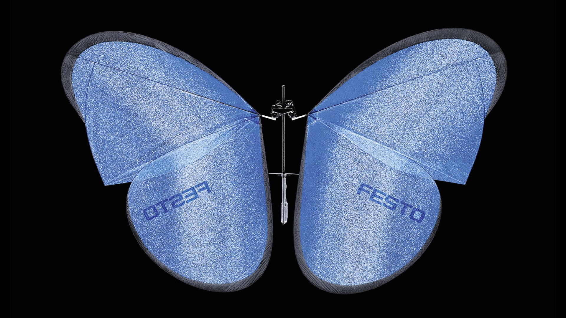
    Idea & Design
    I checked a lot of information About ornithopter on the Internet even bought a book aerodynamics of ornithopter.
    I found that most of the flapping wing power systems use brushless motors.
    Although this is a very mature program, it is mostly used in Bionic BIRD-robot projects.
    taht means the robot will fly like a bird, not an butterfly.
    In order to make it more "bionic", I decided to give up this easy-to-implement power system of brushless motors and try to make it by two servos as the driving force.
    That will make my robot look more like a real butterfly when flying.

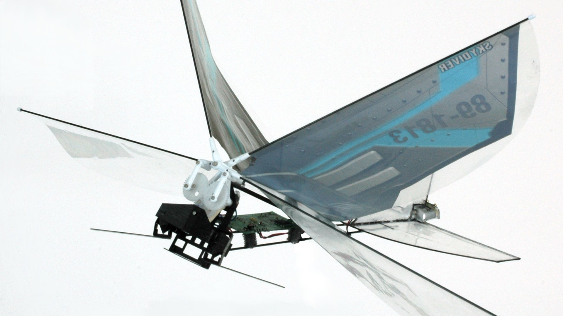
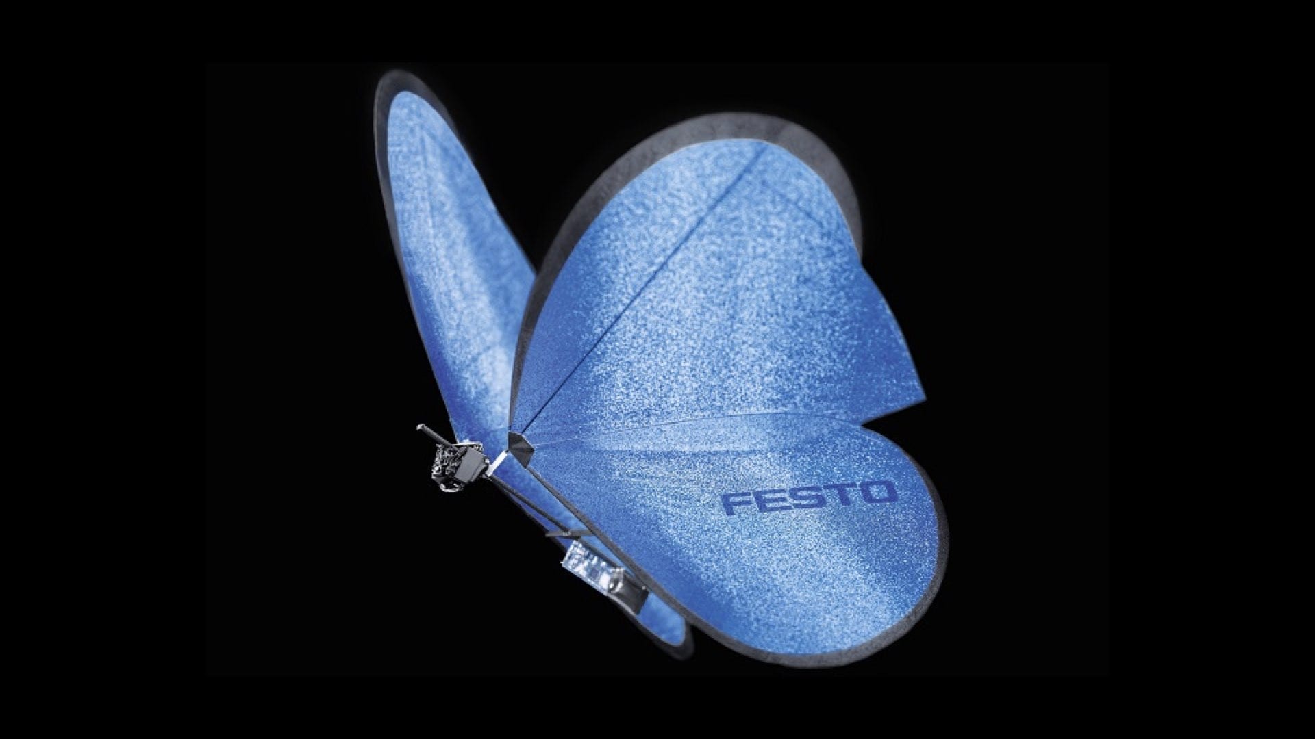
    (Who's done what beforehand?)
    Here are some reference I found and thanks so much for helping me on this project:
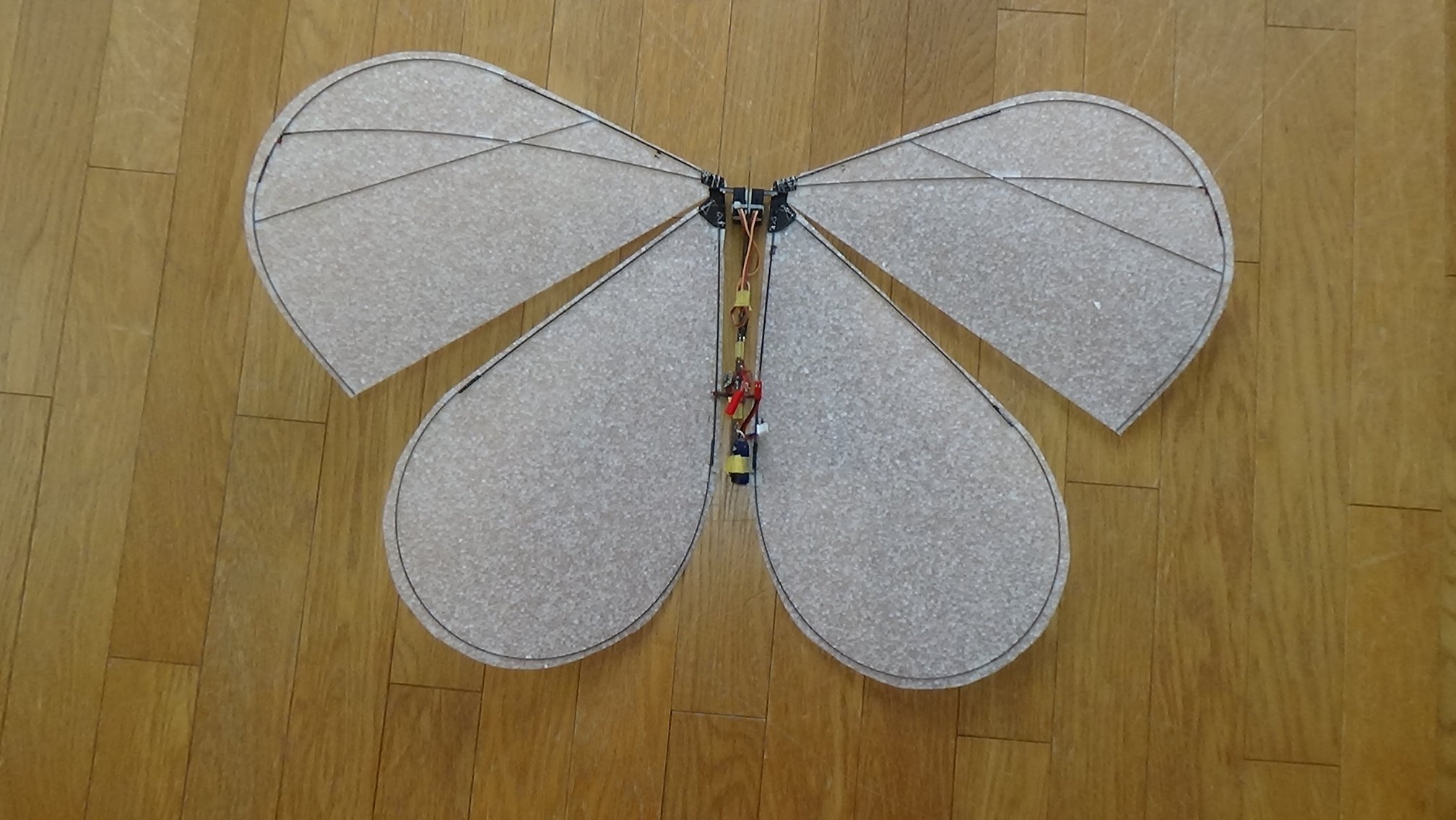
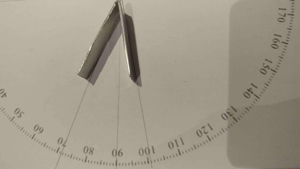
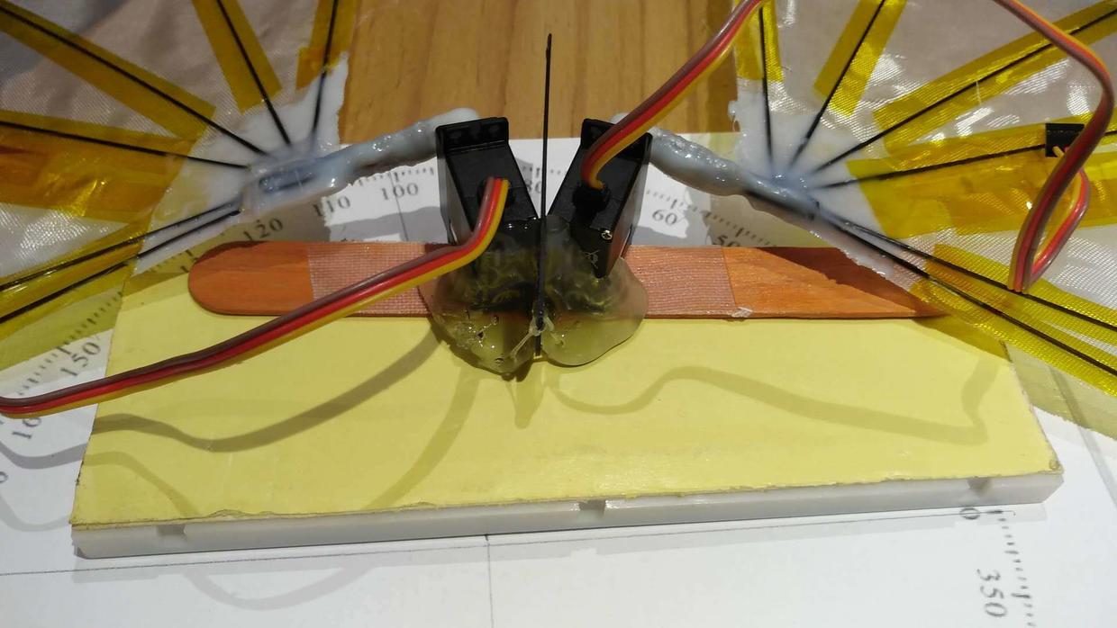
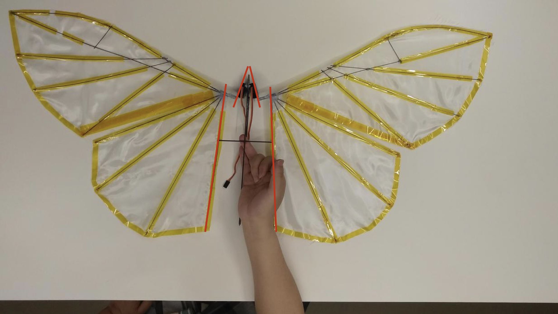
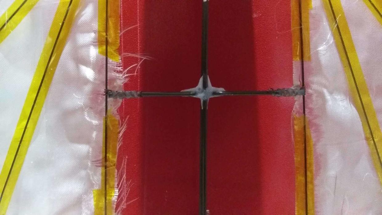
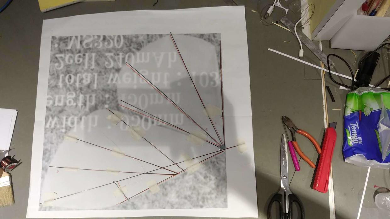
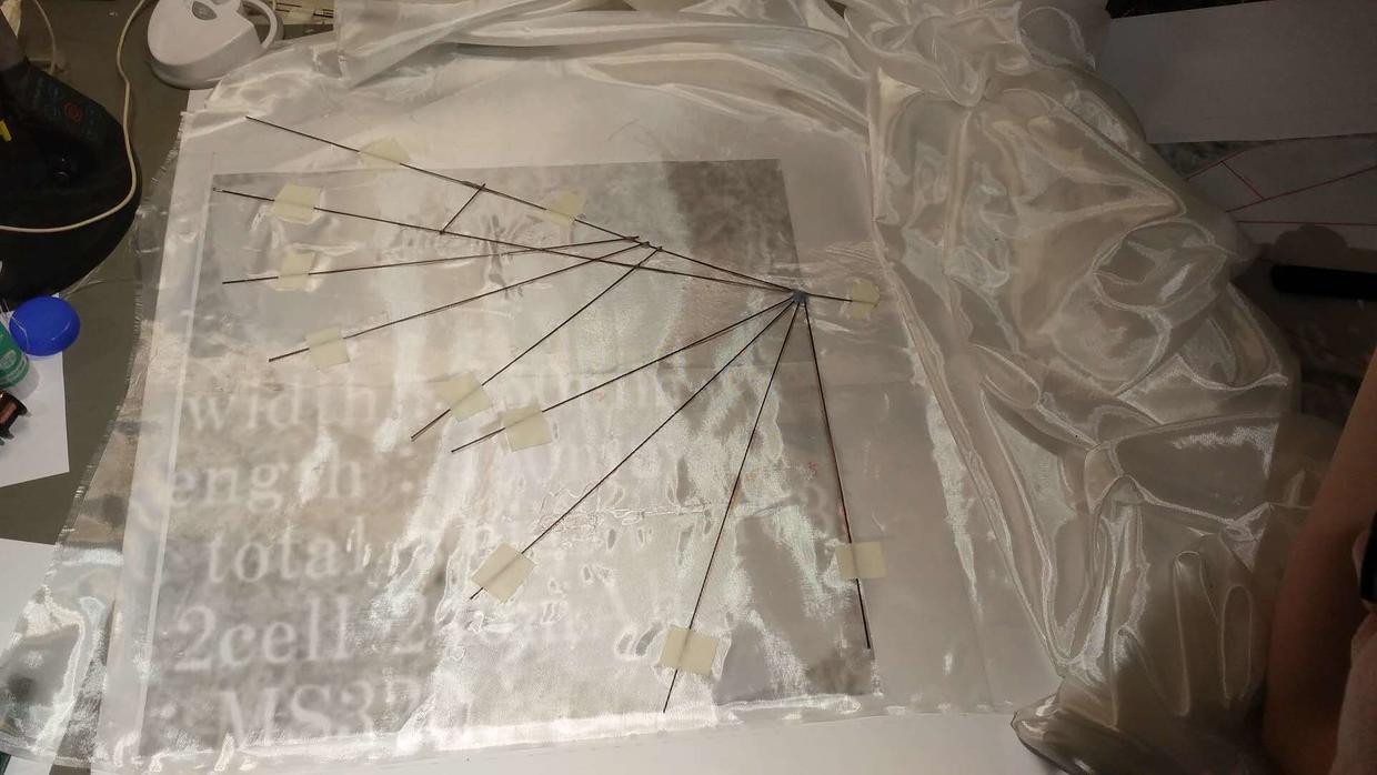
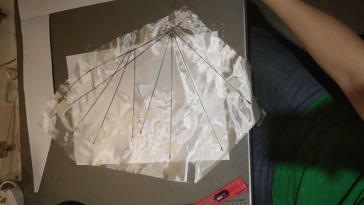
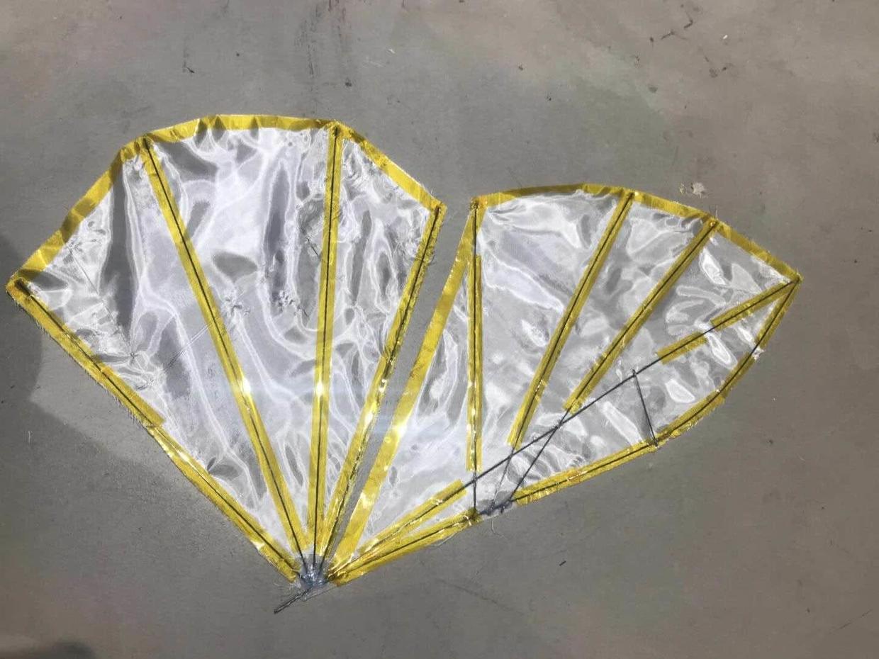
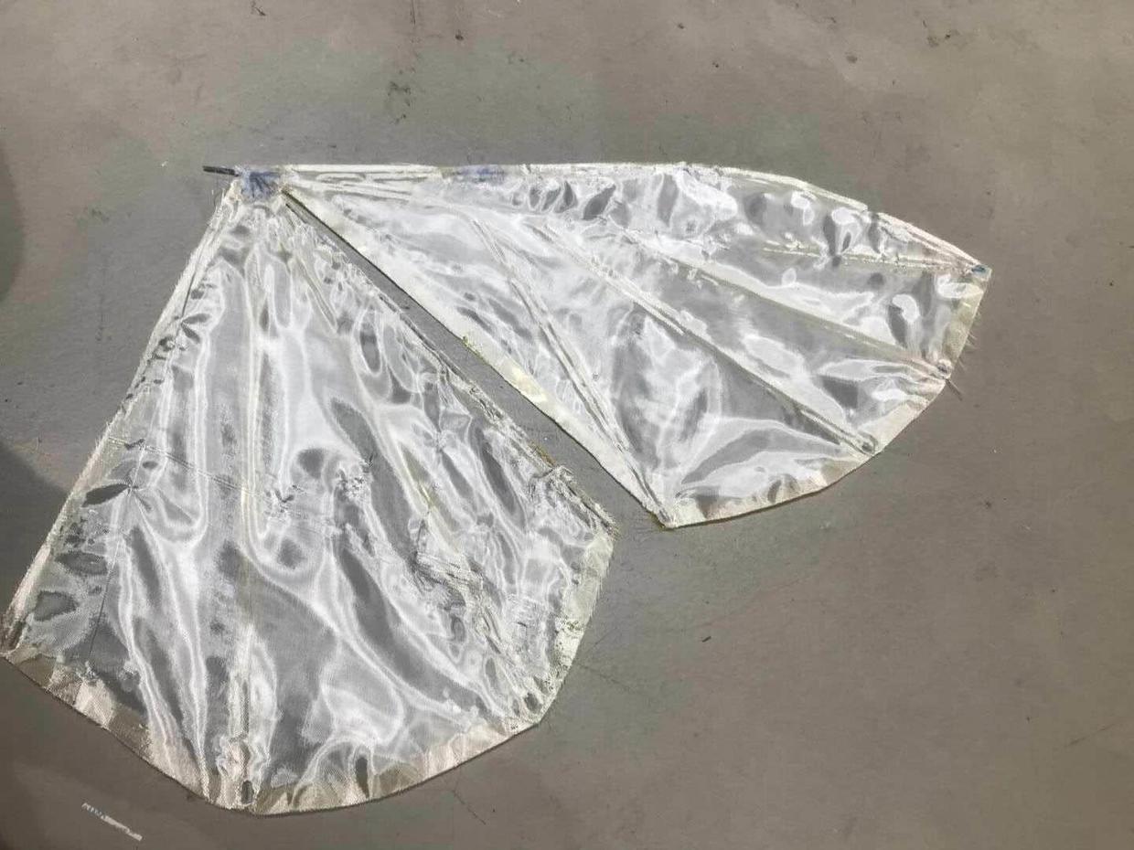
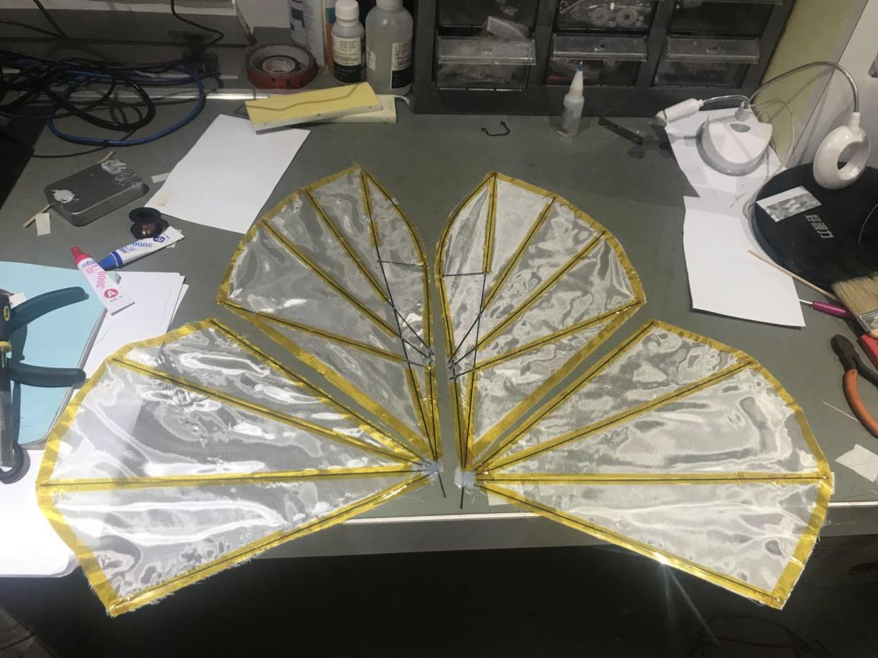
  • 1. The first one is eMotionButterfly a company that specializes in the research and manufacture of bionic robots.
    It should be their earliest practice with the possibility of 2 servos aircraft.

  • 2. Mr. Kazuhiko from Japan
    He has a Youtube channel specifically for recording the ornithopter he has made and a aircraft online community RC Groups
    He really has made a lot of great Ornithopter.
    Mr Kazuhiko is a doctor and used his spare time to make flapping aircraft. He also published the latest project progress picture to his Facebook for record, big help for my project.
    (I respect him very much because this project and hope I may have a chance to thanks him in person)

  • 3. Mr Y.Takemura also from Japan
    Like Kazuhiko, he used Youtube to record his own ornithopter projects. My wing's shape and structure refer to his video. I am very grateful for his reply to my queseton,as well as tips and help on many key issues.
    (I also hope to have the opportunity to thank him in person someday)

  • 2.Modeling and Structure

    Butterfly-Version 1

    2.1 Making wings

  • I decided to start with making the wings of a butterfly. So I directly print out a screenshots of the video, like this.
  • Then cut the picture into 2 pieces, then print and stitch it together.
  • The next step is to solve the problem of structural strength: We finally used a quick-drying AB glue to glue the skeleton, because the experiment proved that the 502 glue not good enough, only the AB glue.
  • Since AB glue does not adhere to metal, it is useful to use copper platinum paper as a mat pad in the following method. In order to reinforce the early stage, it is still necessary to use copper wire to fix it.

  • Then I chose the fiber membrane as the material of wing because its lighter weight per unit area. (However, subsequent actual tests prove that this may not be a good choice)
  • Then I finally completed a pair of wings

  • 2.2 Another try (Simulation)

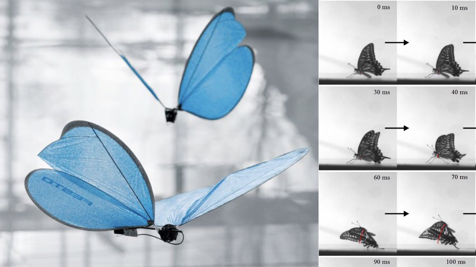
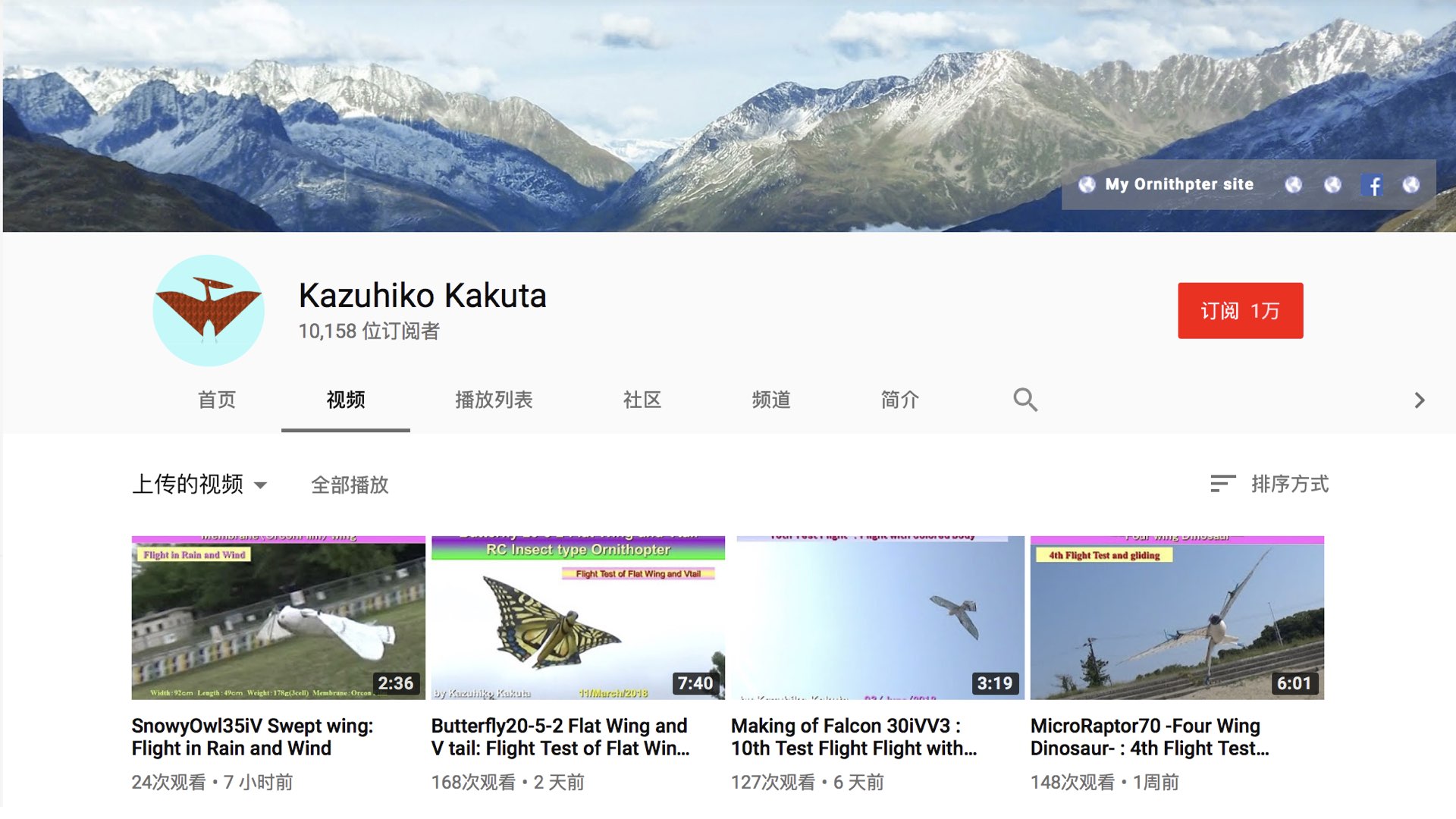
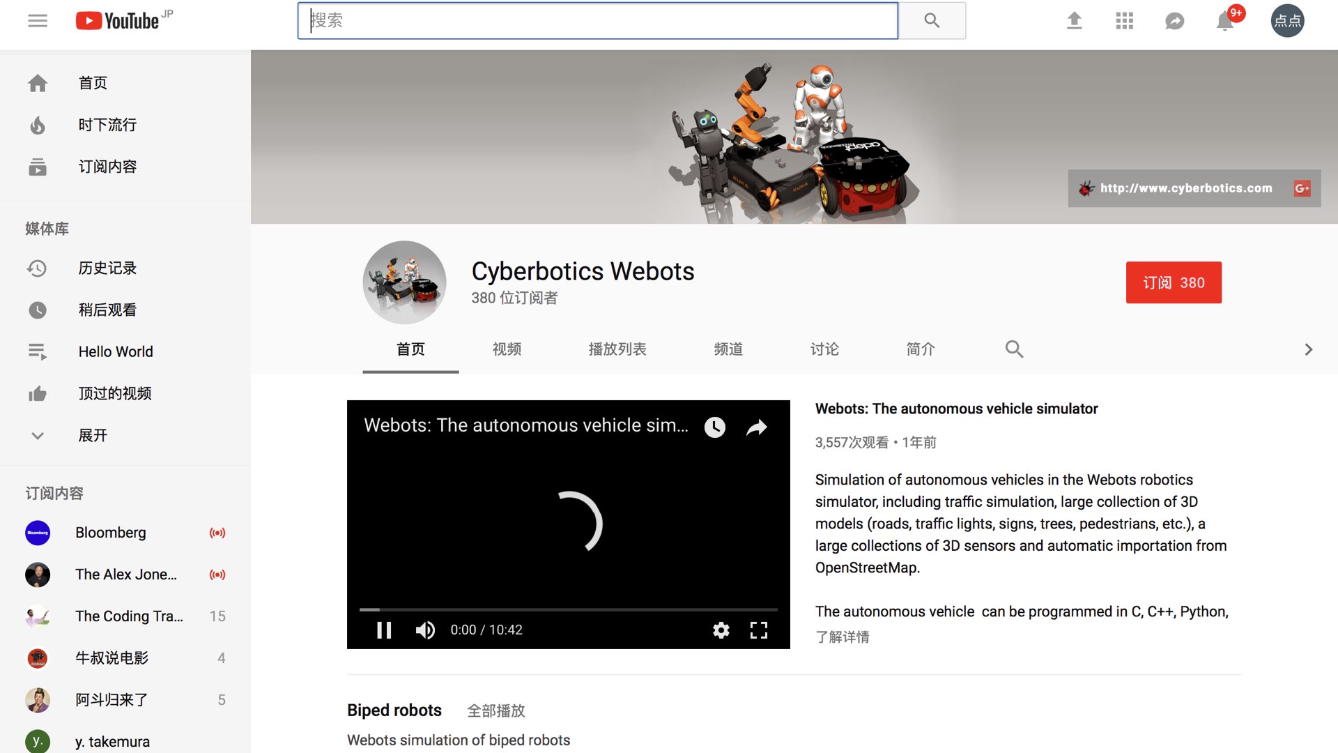
    background
    The few successful cases of using a servo as a power engine add uncertainties to our work. So I continued to check the relevant infrom and found that the books I bought contained mathematical principles for the description of birds and ornithopter, as well as a formula describing the functional relationship between power and wing surface area.
    Meanwhile,I saw that Kazuhiko also tested the same servo and the flight of different surface area wings in his own channel to record the ratio of pull ratio.

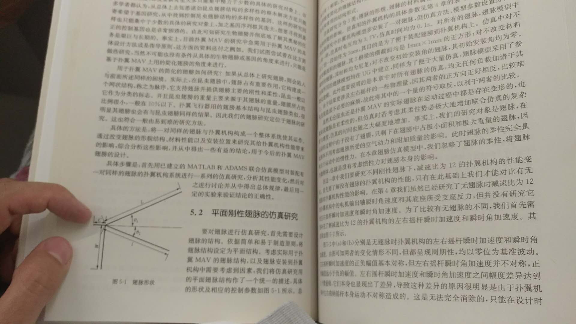
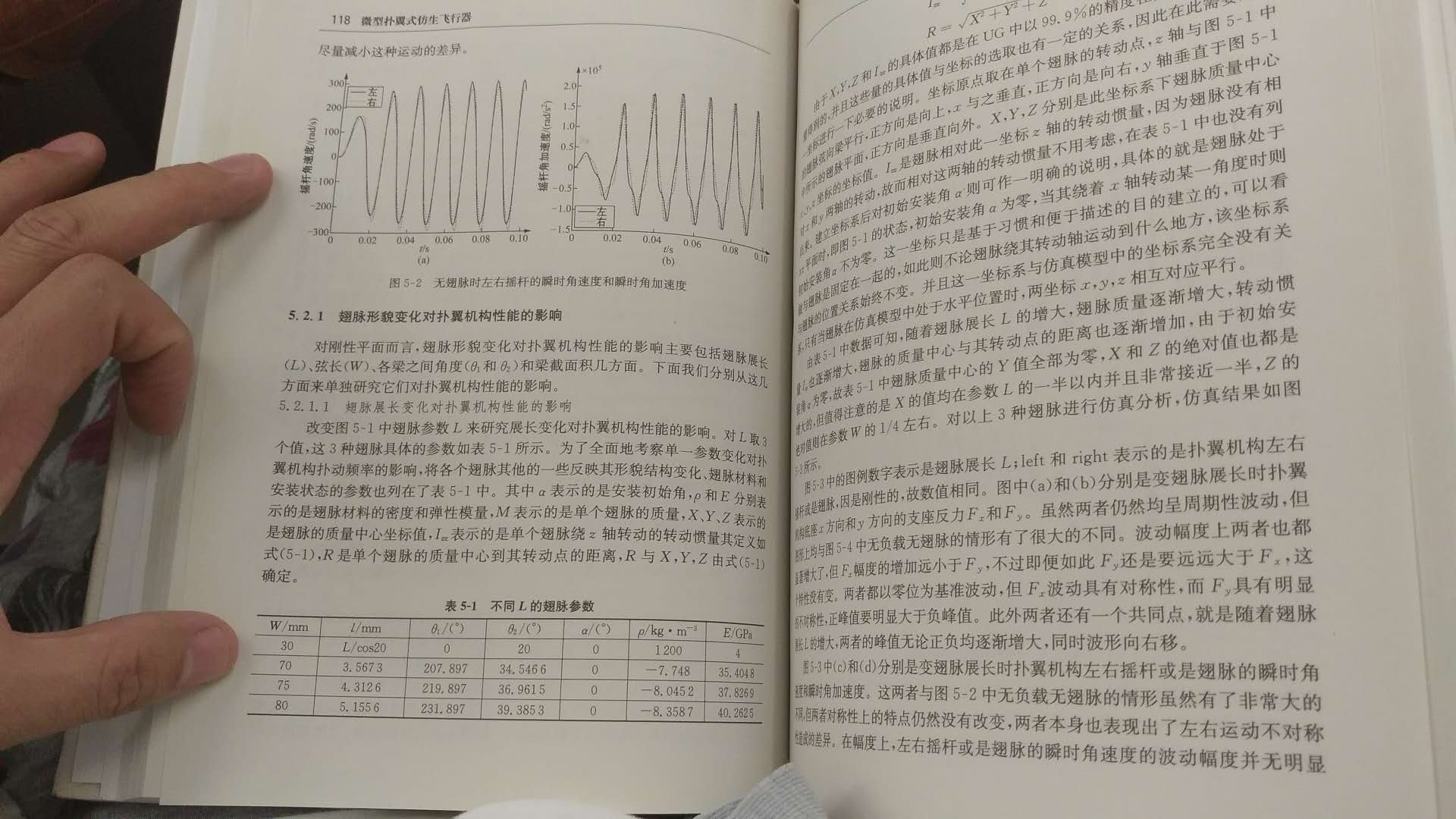
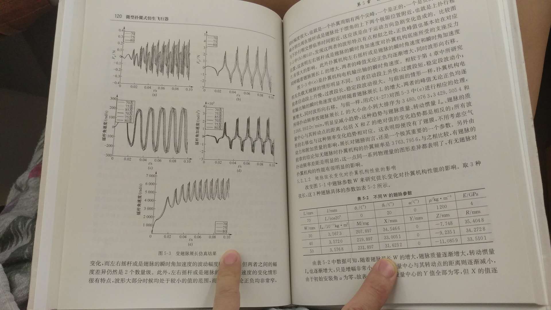
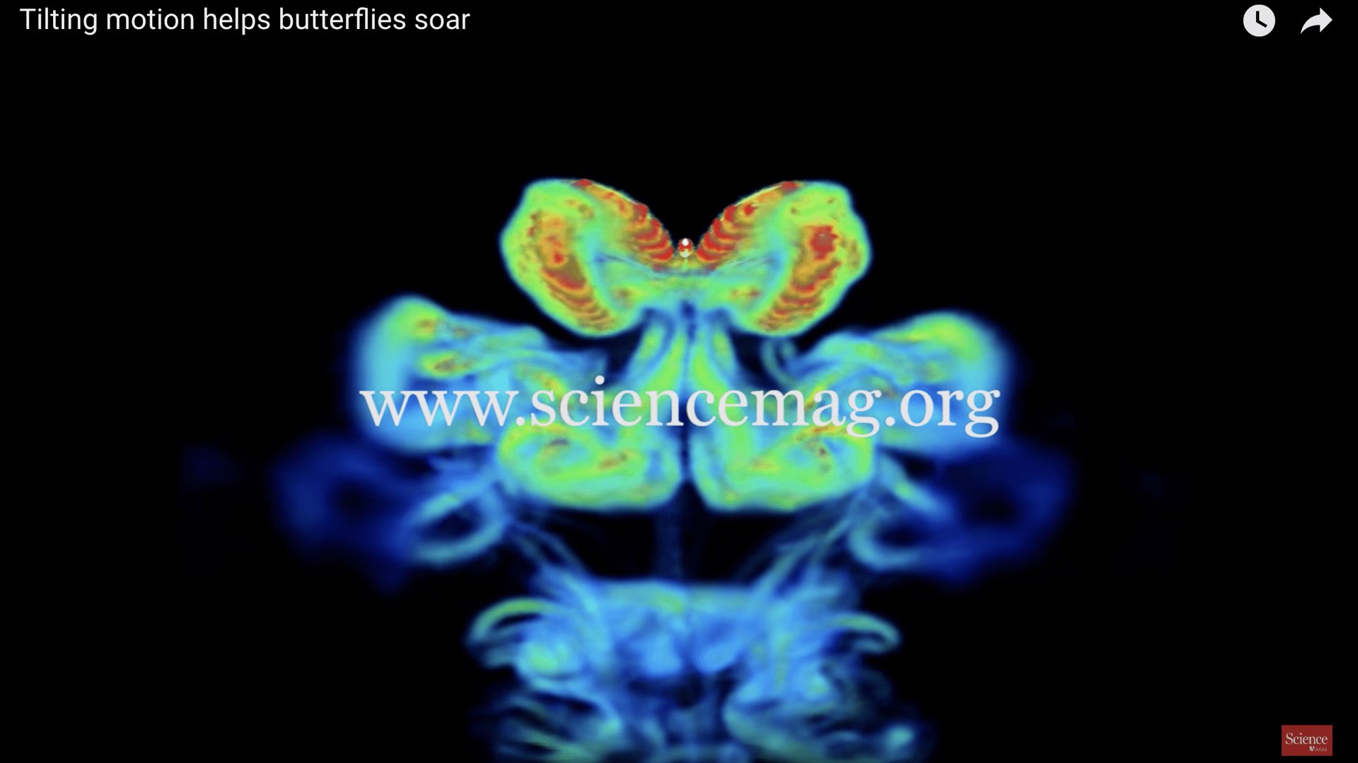
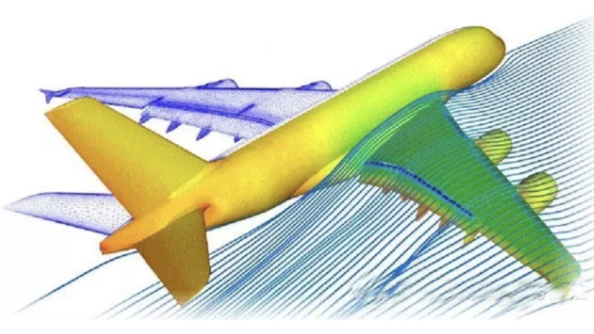
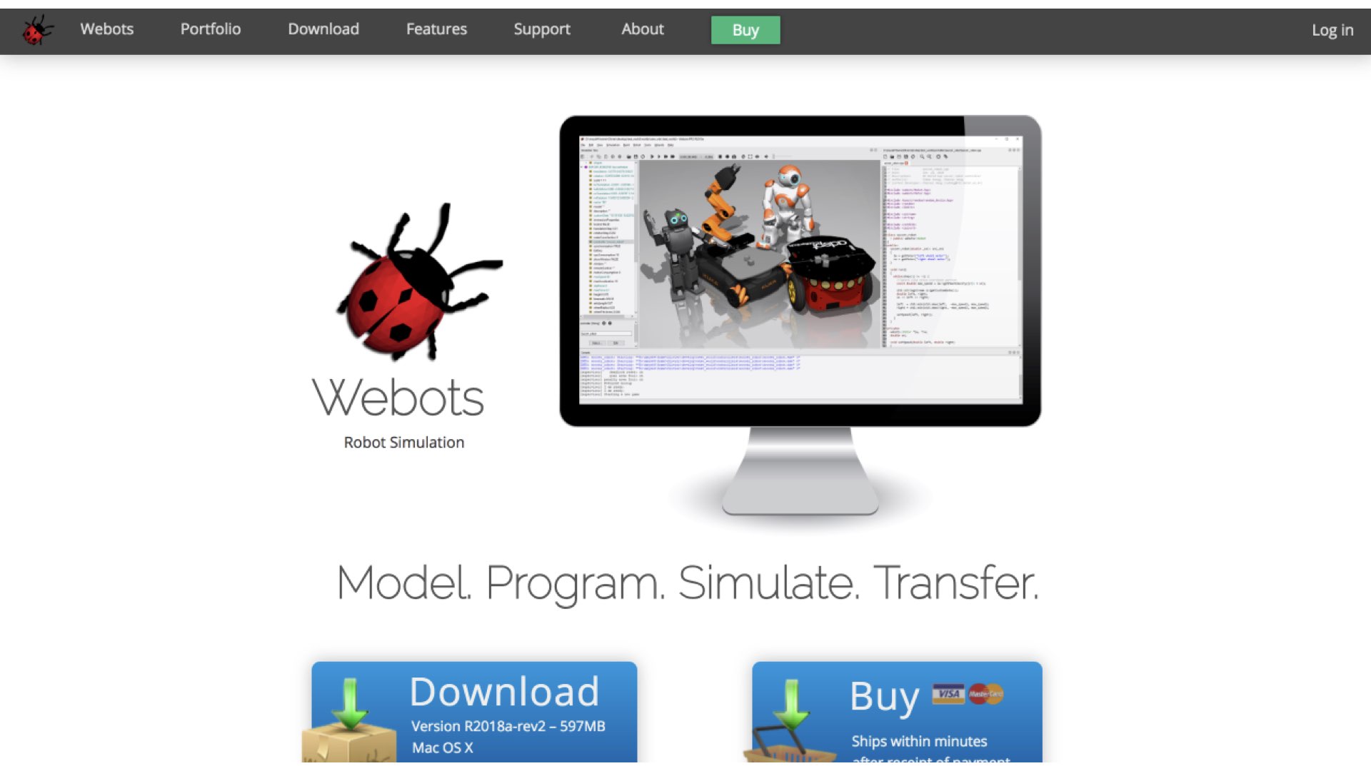
    My Idea
    So I suddenly thought: Is it possible to use what software to simulate the flying process of a butterfly robot?
    My idea is to build a model based on the specific parameters of the servo and build several wing models of different sizes. After assembly, place them in a simulated gravity field.
    I searched for some software that simulated the flight status of the aircraft. I guess there must be a mature off-the-shelf app to do this job.
    So I made a statement in the "Wechat moment" and asked if there is any software suitable for such simulation.
    Here are some reference results:

  • 1.JSbsim & Yasim: YASim is one of the two most commonly used FDMs in Flightgear. JSBsim is the other popular FDM used by the Flightgear community.
  • 2.Finite Element Analysis
  • 3.Ansys
  • 4.Cyberbotics Webots
  • 5.Google seems to have a flapping open source project, but I didn't find it.
    However, time pressure, I didn't followed up those research. Hope someone who are interested in it will continue this job.

  • 2.2 Making body & Hardware

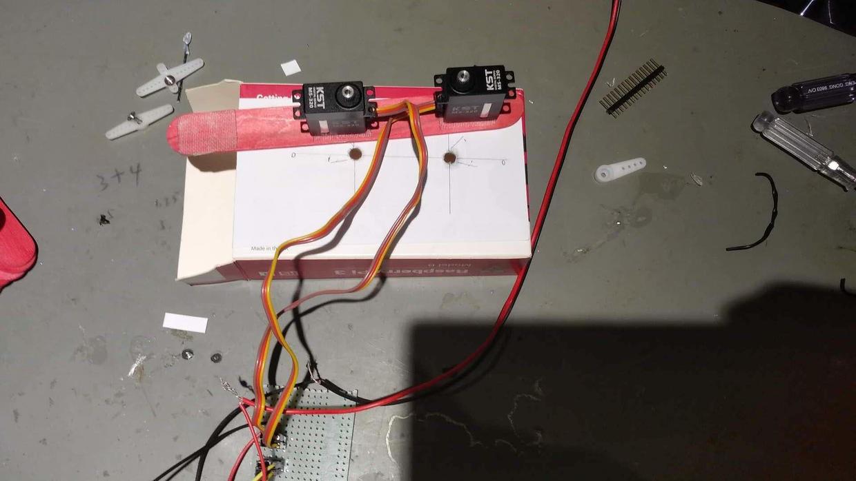
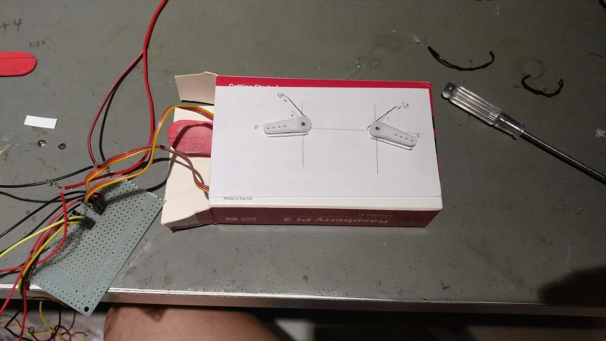
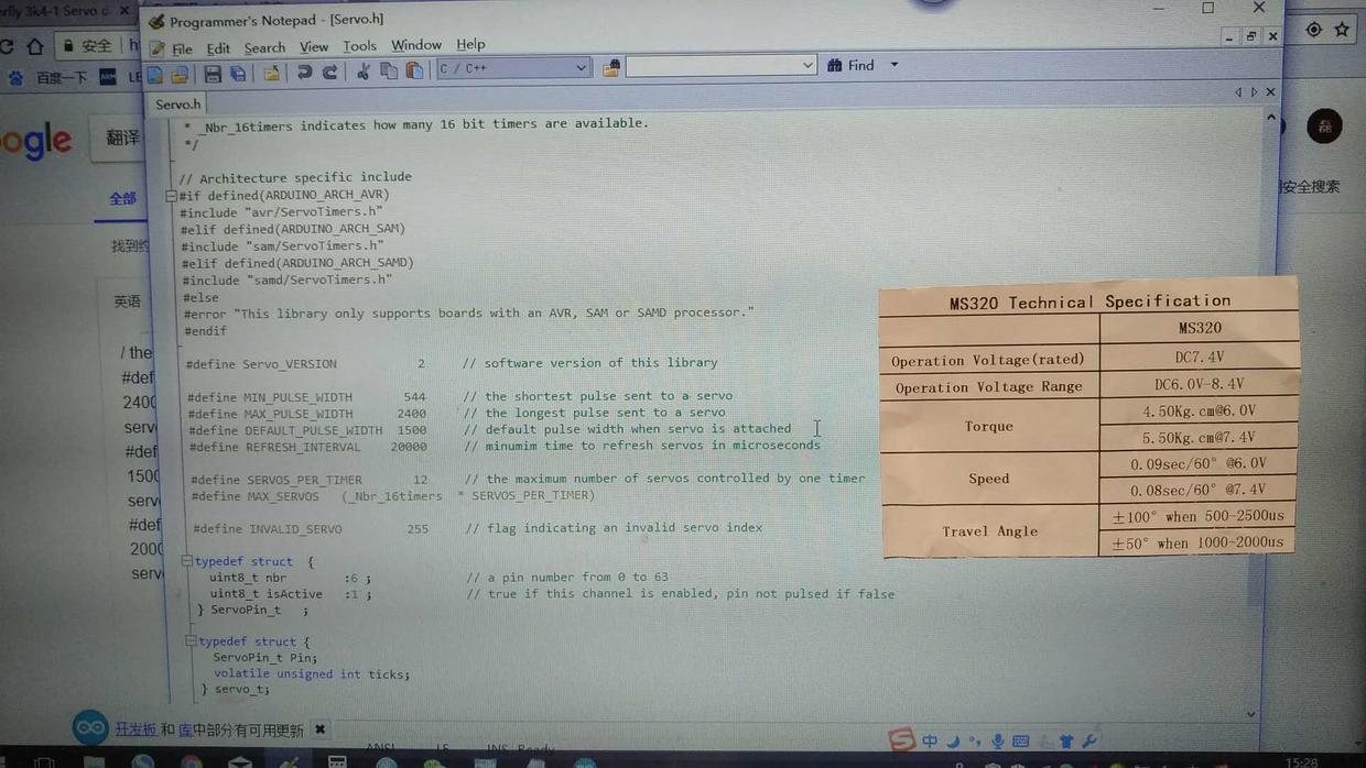
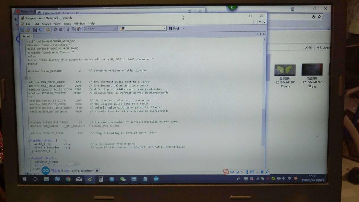
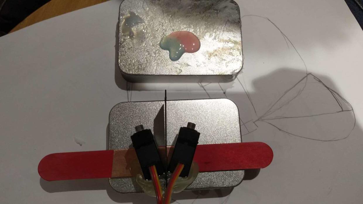
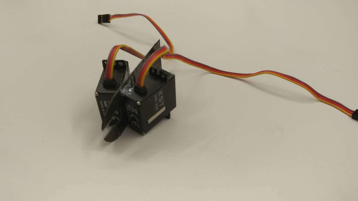
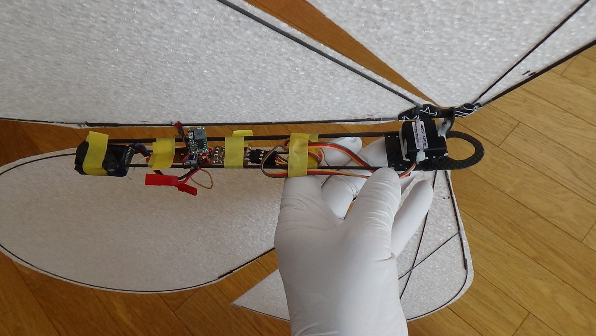
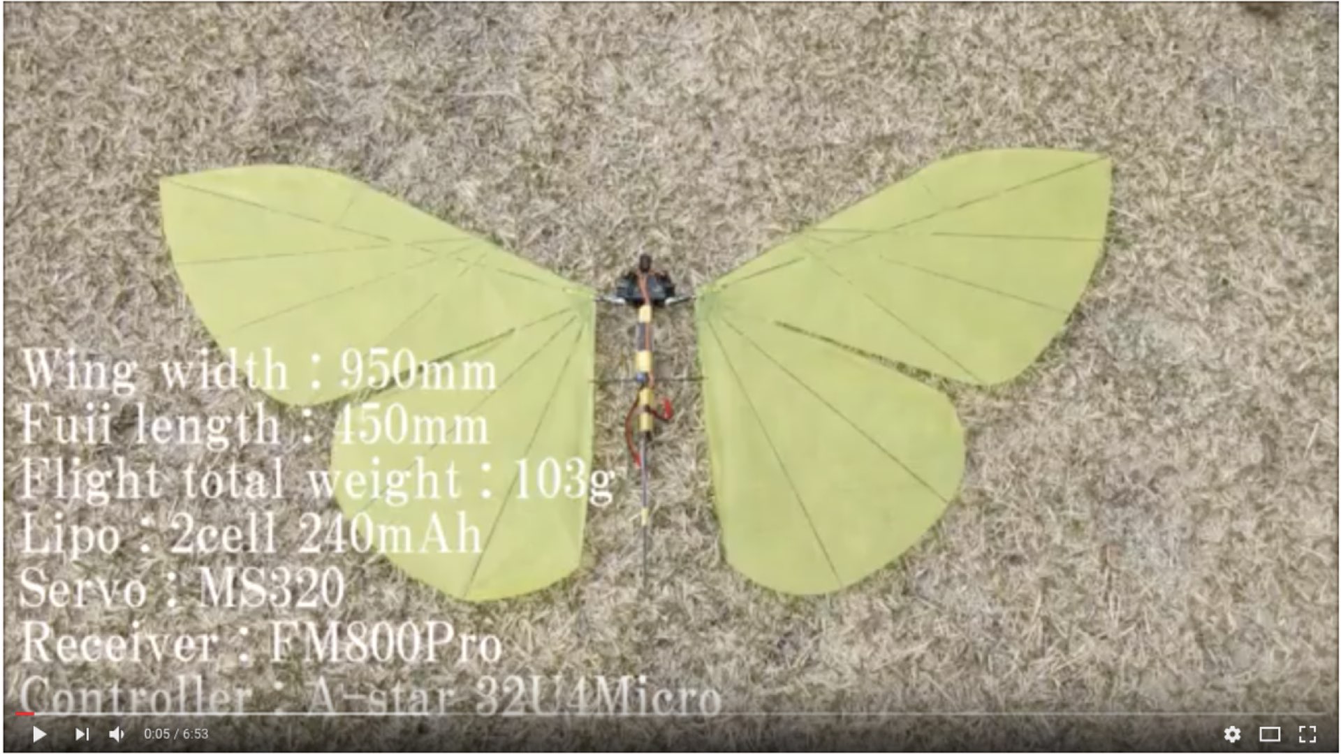
    The KST-MS320 servos arrived and we are planning to have a test. Although the Technical Specification point out that:

  • 0.08se/60 degrees 7.4V
  • +- 100 degrees / 500 - 2500us
    But we still need to have a actually test how fast it can keep when it travel exactally 60 degrees
  • First, we prepared a paper box, then we smashed 2 holes and installed the steering gear like this.
  • Although the effect is good, the actual test result shows that when delay is 0.08se, the servos only travel 45 degrees NOT 60 degrees.
  • So we add a sliding rheostat to control the rotational frequency of the servo.

  • Then we added wings on the servos. For the structural strength, we used a lot of AB glue at the servo connection.
  • Because the middle edge of the wings needs to vertical, the servos needs to be placed at an angle of 30 degrees.
  • After determining the correct angle, we are ready to firmly fix the servo at right angle (30 degrees).
  • In order to ensure that it does not shape, we use a metal bent a 30 degree angle, used to fix the servos.
  • Then glue the body of the butterfly with AB glue and stick a fixed bracket at 1/3

  • End