Fab Academy 2018
Electronics Production
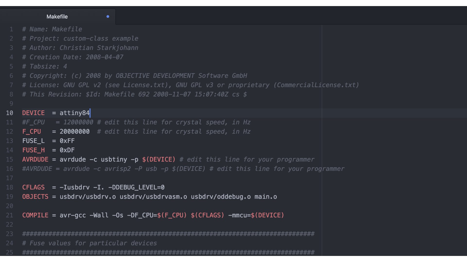
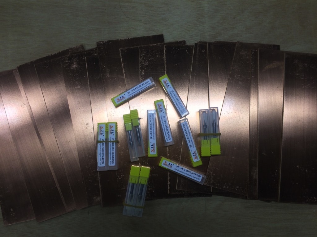
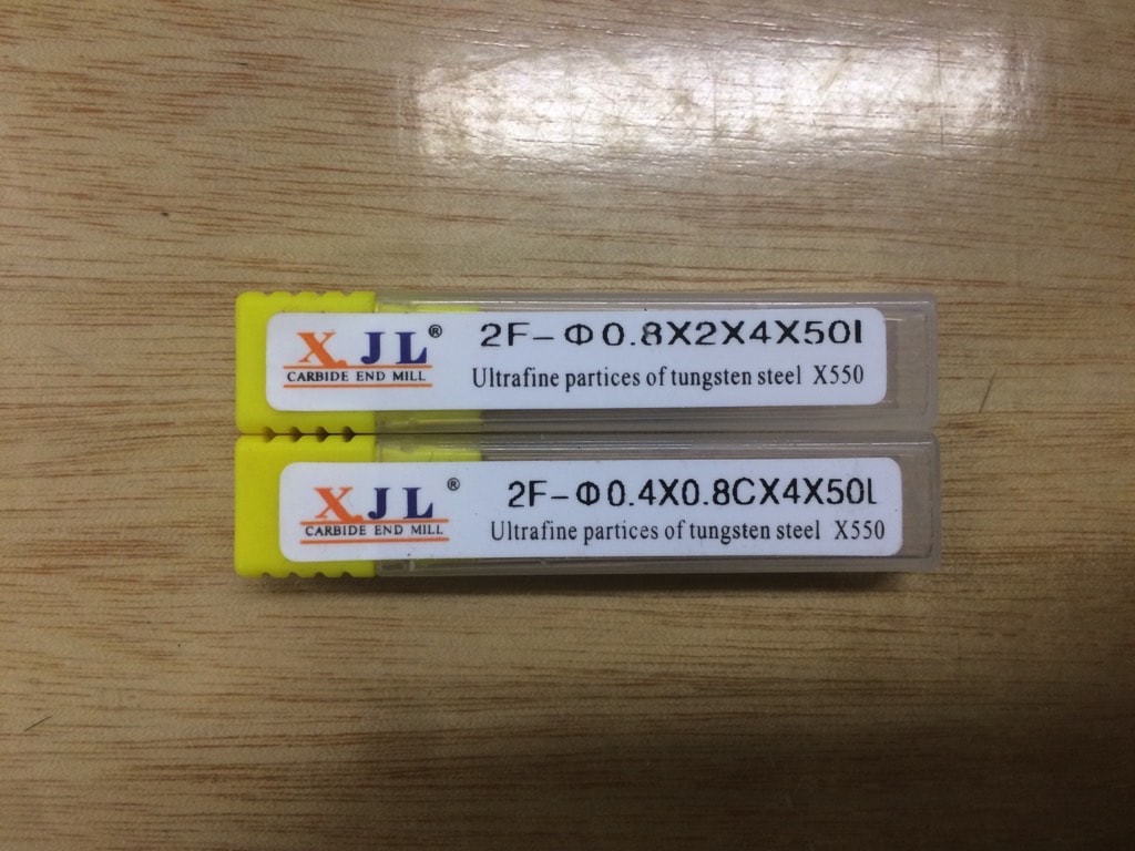
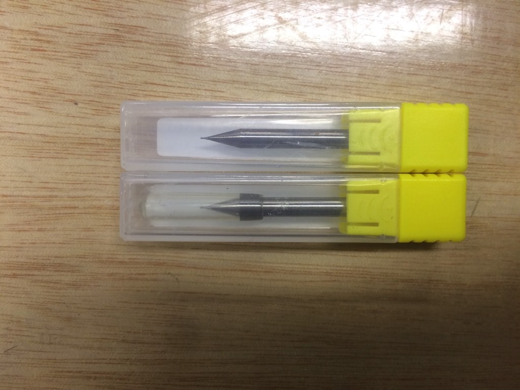
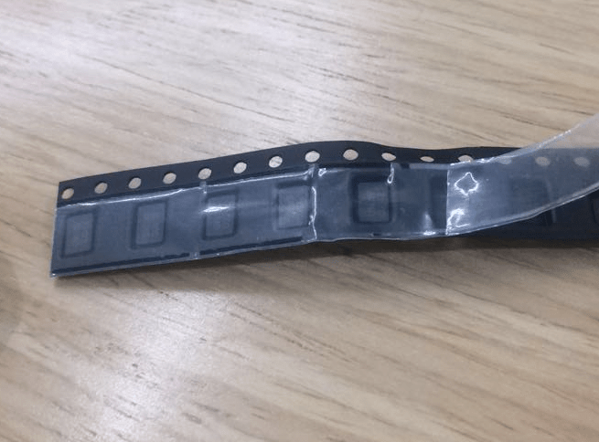
Follow the Tutorial, note and other students website in 2017, I bought those copper-clad laminates,0.4mm & 0.8mm End-mills and other Electronic components from Tamll.com Remarkably we used Attiny 84 micro-controller (follow the Tutorials 2018) not Attiny 44. It’s almost same but Attiny 84 has more Program Memory /EEPROM /RAM Size. About crystal, I can’t found the 1206 inch size (I believe there is no 1206 crystal in China)so I buy a minimum size 20MHz crystal.
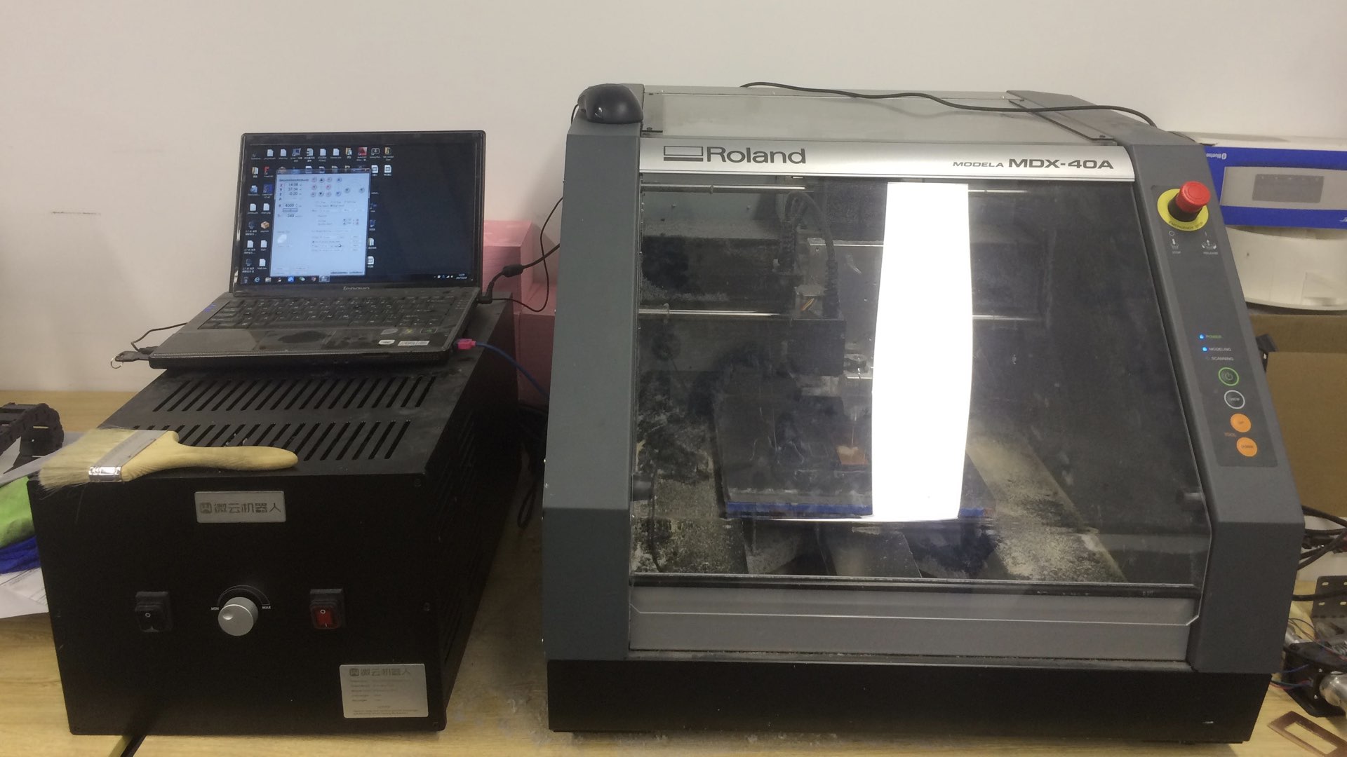
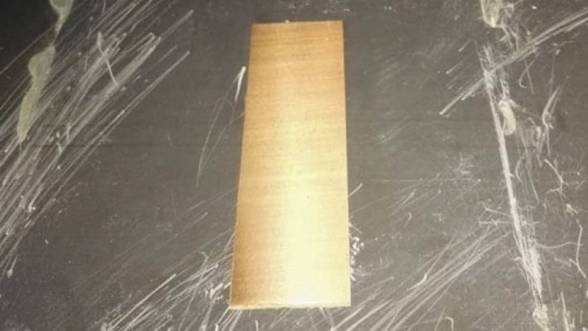
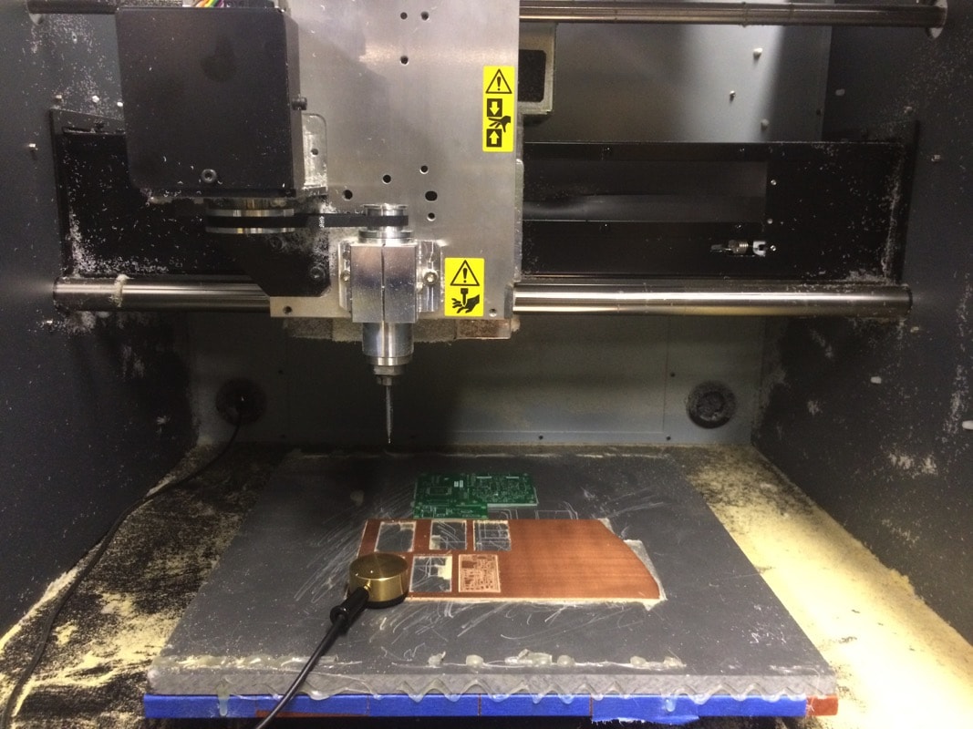
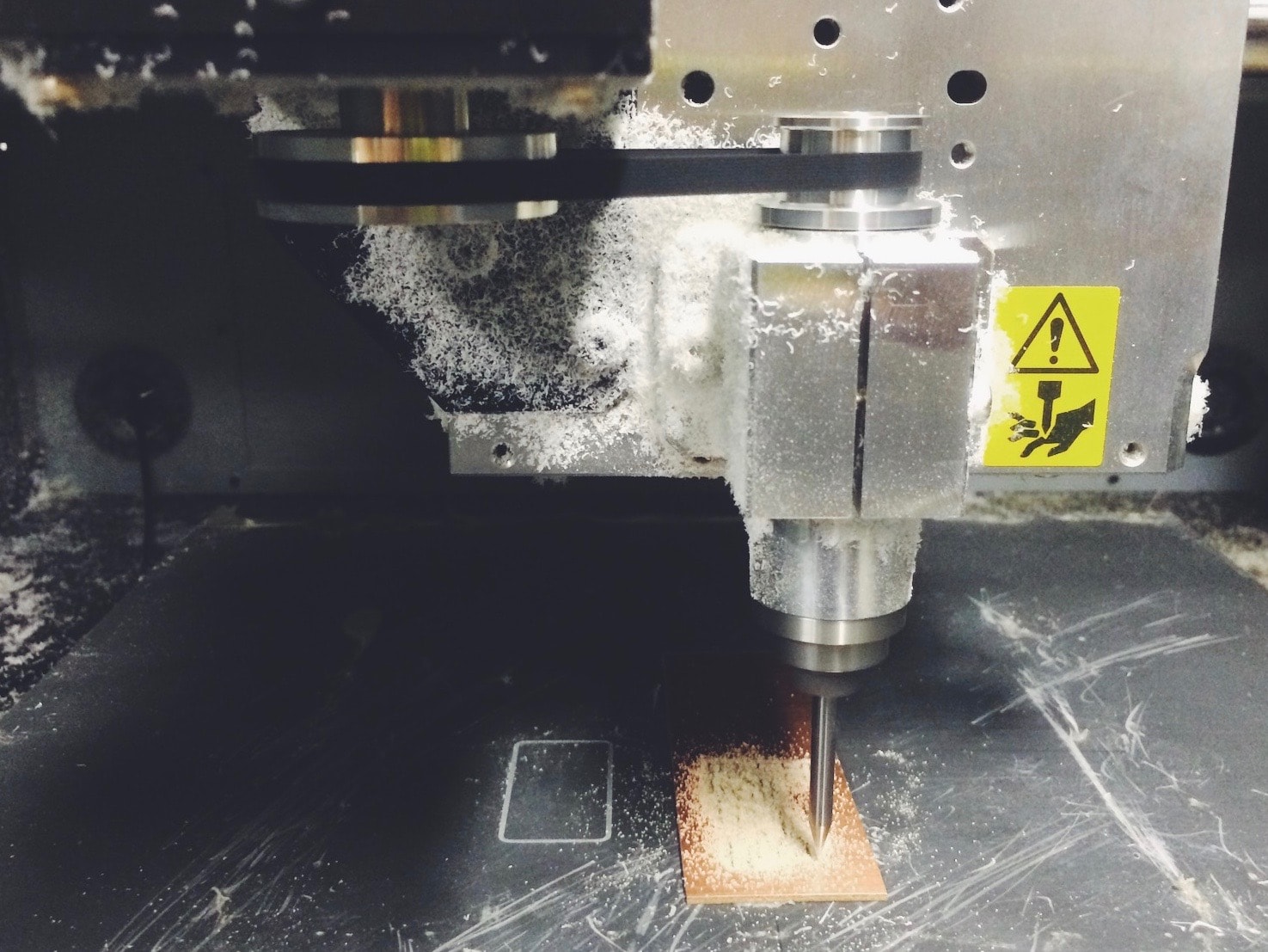
Our milling machine is Roland MDX-40A. I learn from the user's manual and software, knowing how to operate the machine. One of my friend suggest me cutting the copper-board smaller make the surface more flatter. (but I think I cut it too small.)
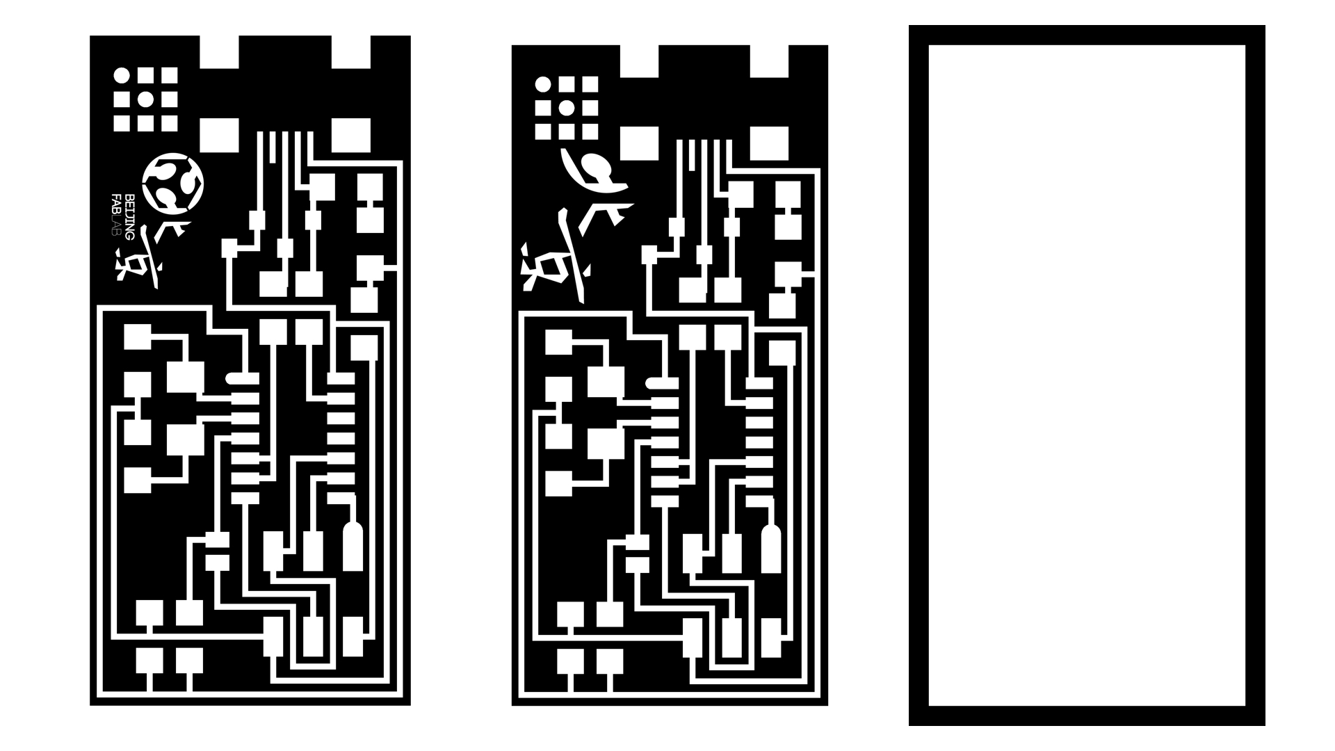
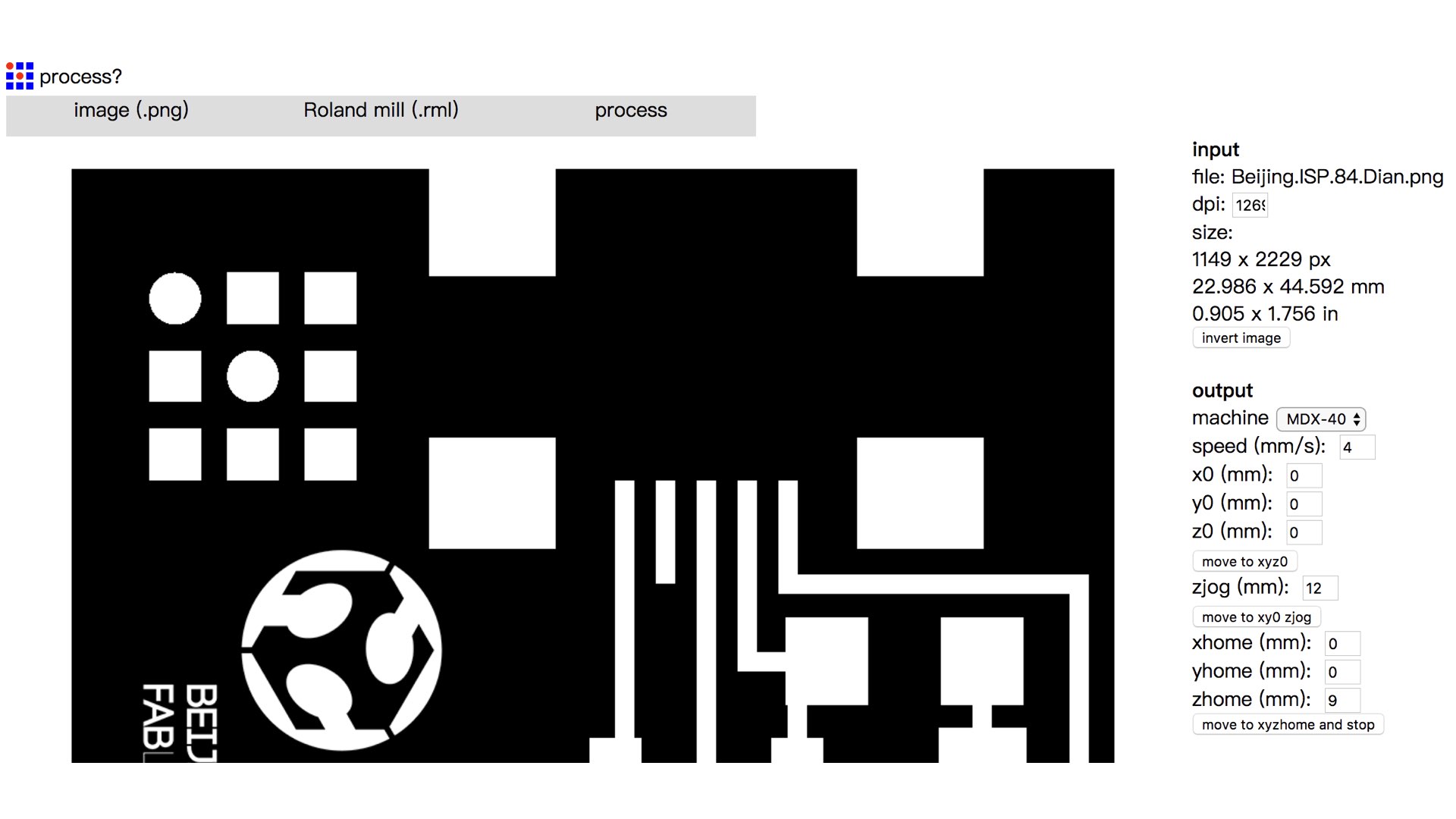
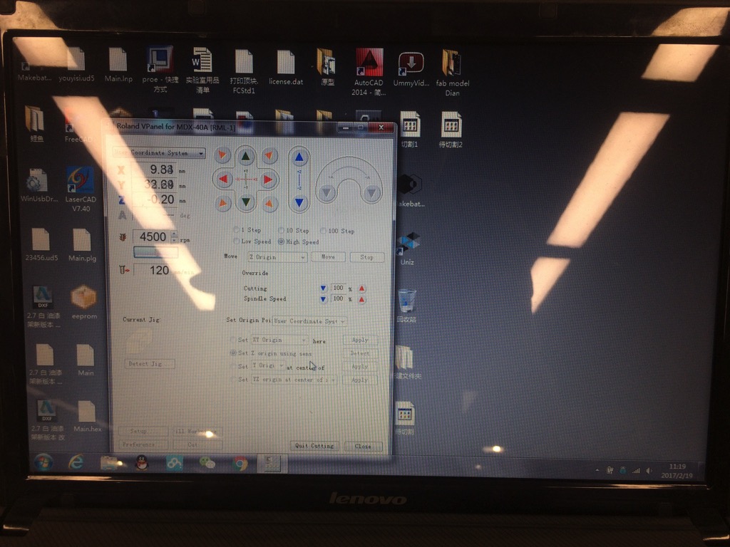
I was deeply interested in Fab modules science I first hear about it. It’s such a amazing tools to control all those fab-machine online. I choose the Fab ISP Parts Layout(20MHz crystal version) and PS our "Fablab Beijing Logo" on it. I used the Web version Here is my parameters setting below:
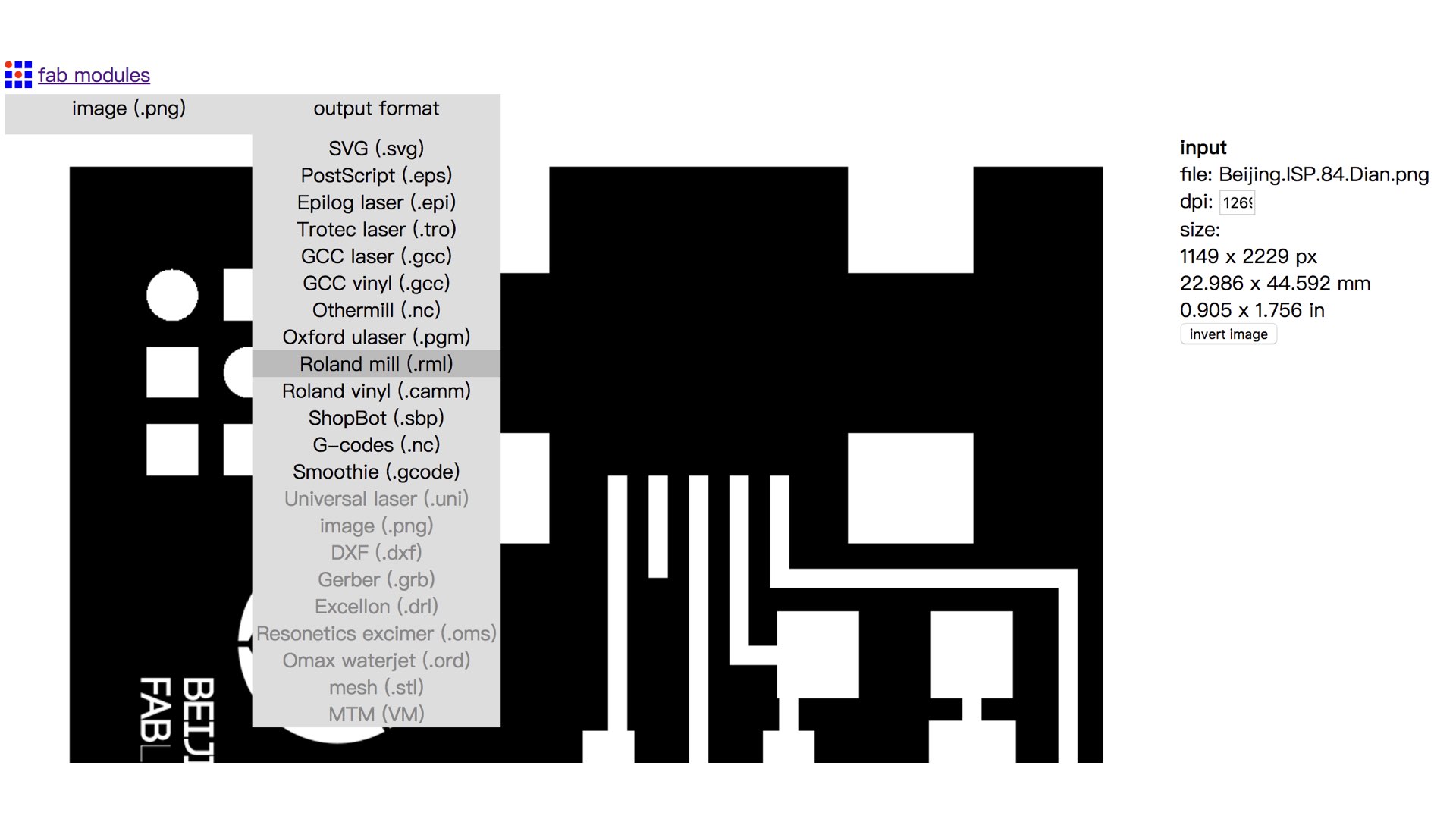
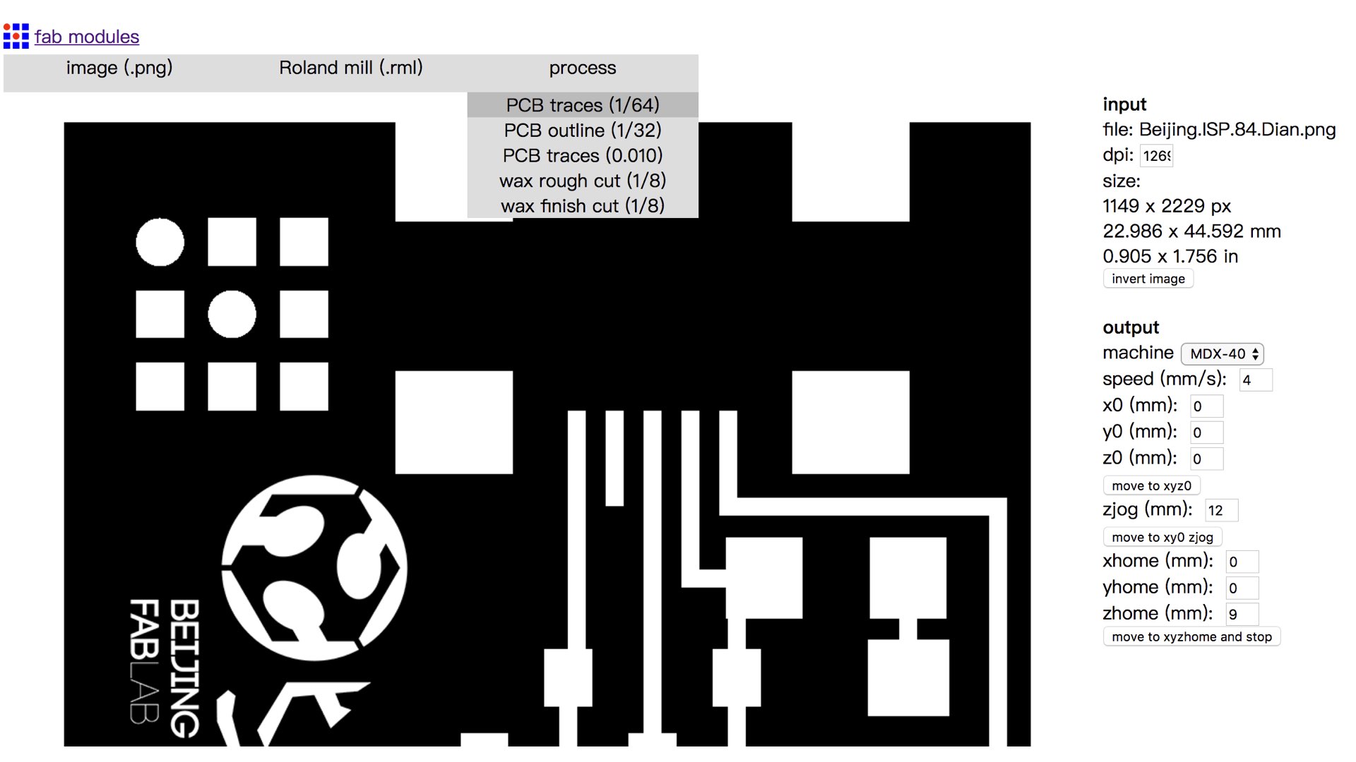
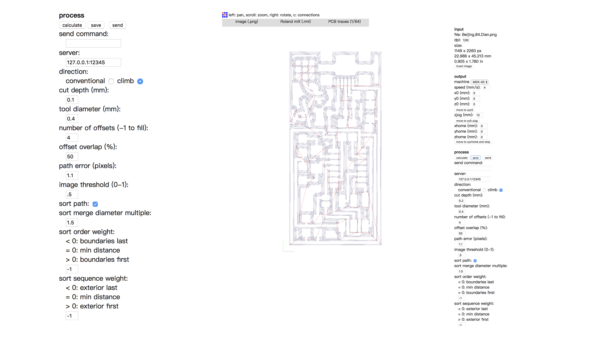
Remember select the "PCB traces (1/64)" Then click calculate & save button.
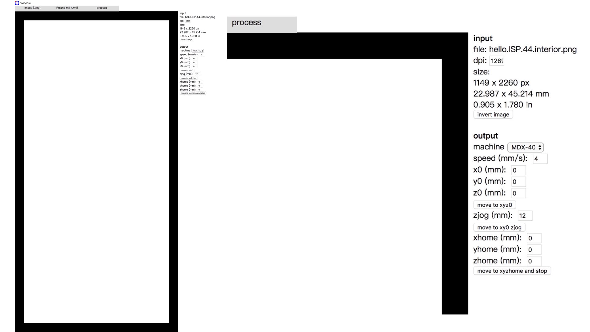
As above, we upload the outline.png file, select "PCB traces (1/32)" then calculate & save the outline file.
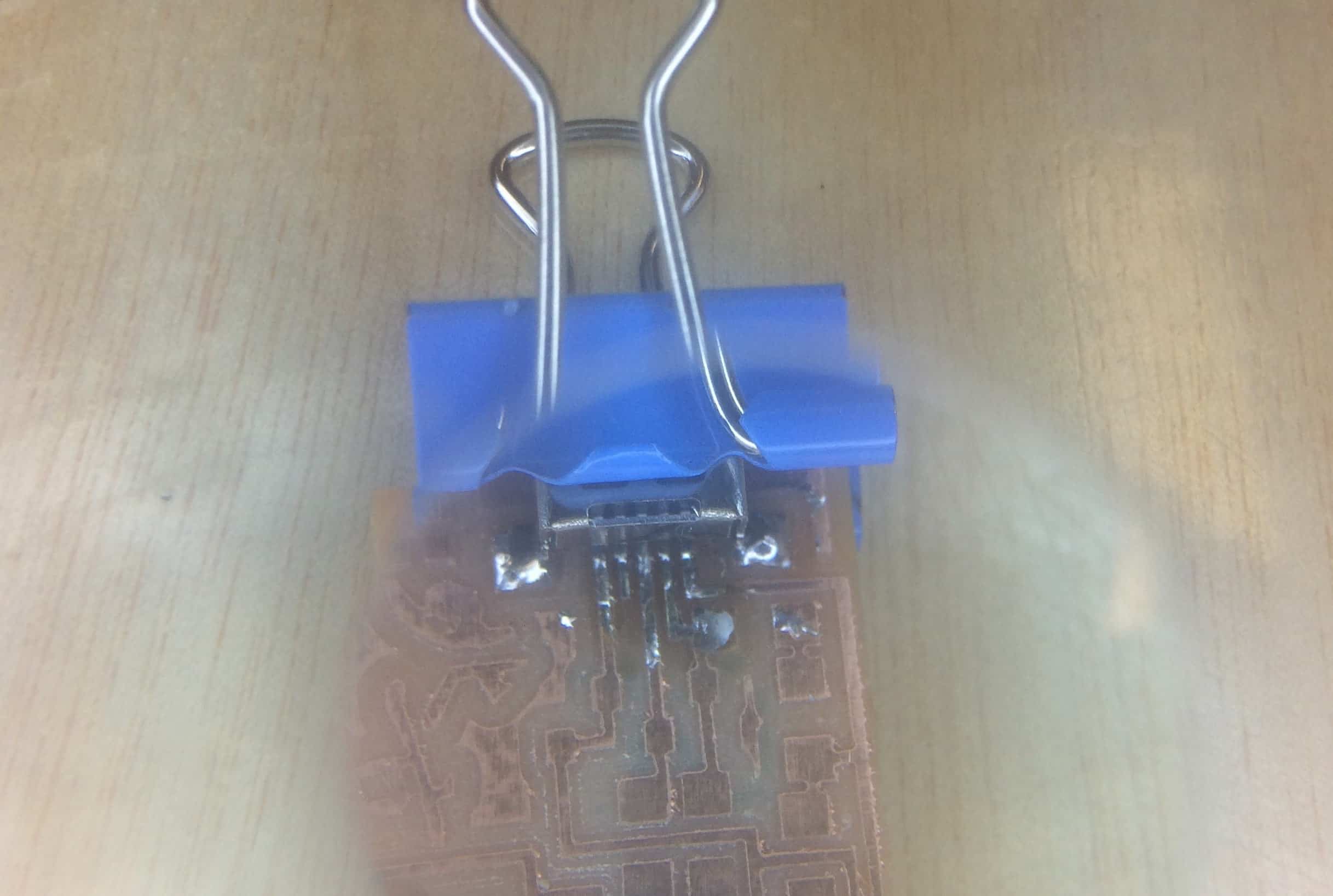
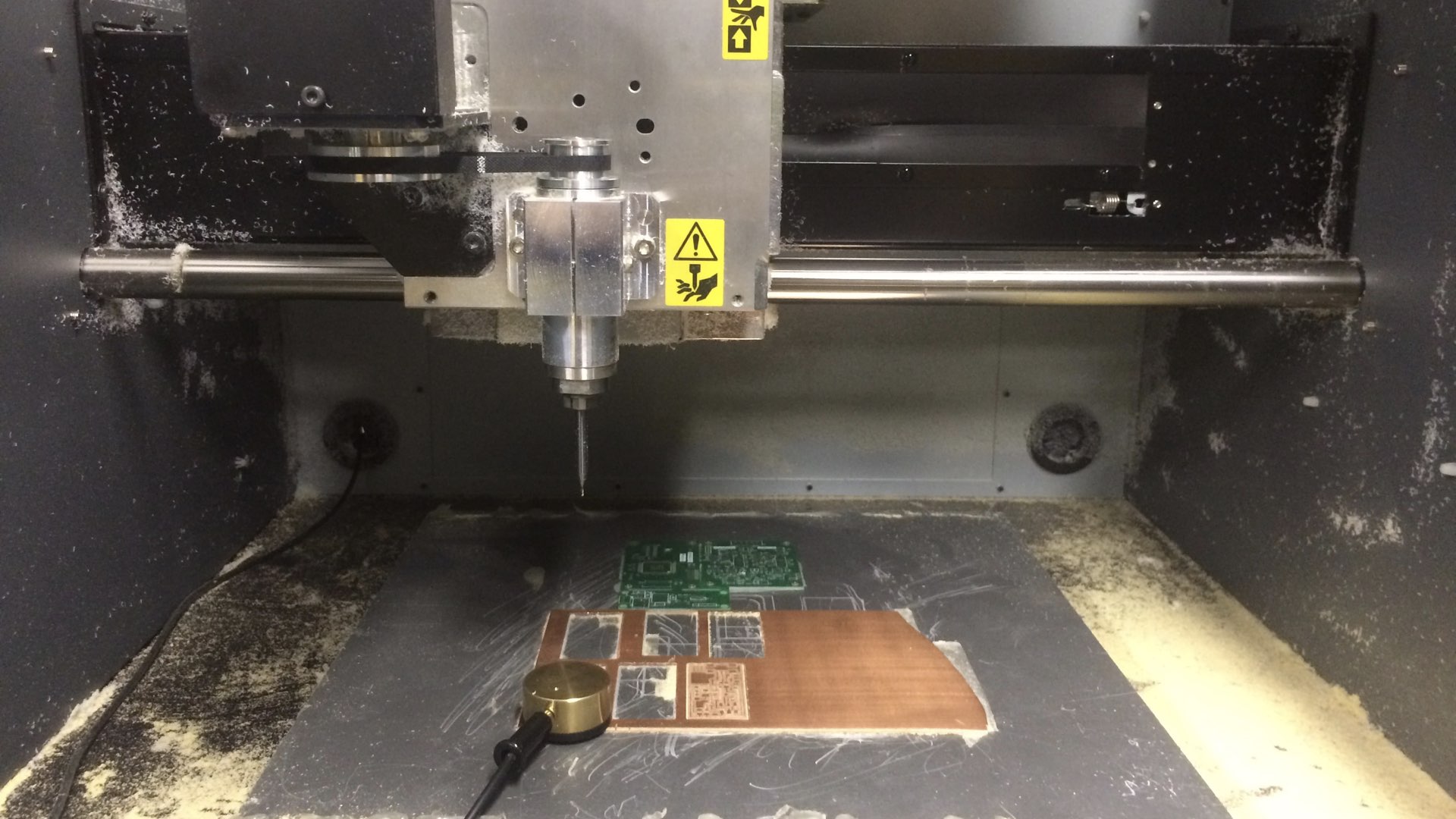
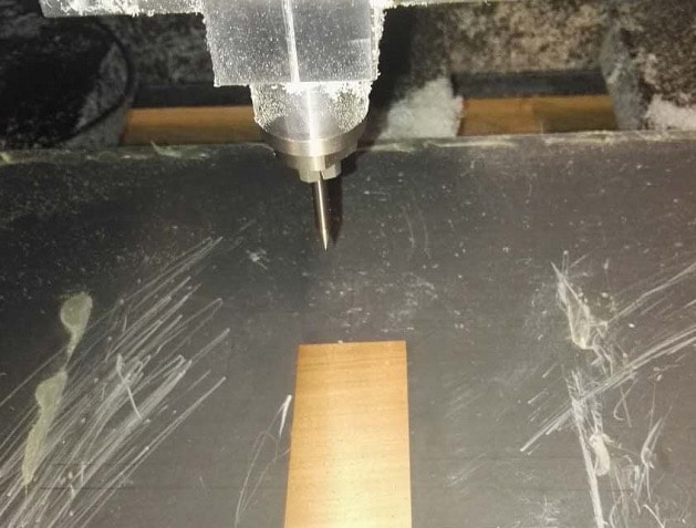
Attach the copper-clad laminates on the base-plate and set the X0Y0 position. Then set the Z0 position with a sensor, import rml file then cut.
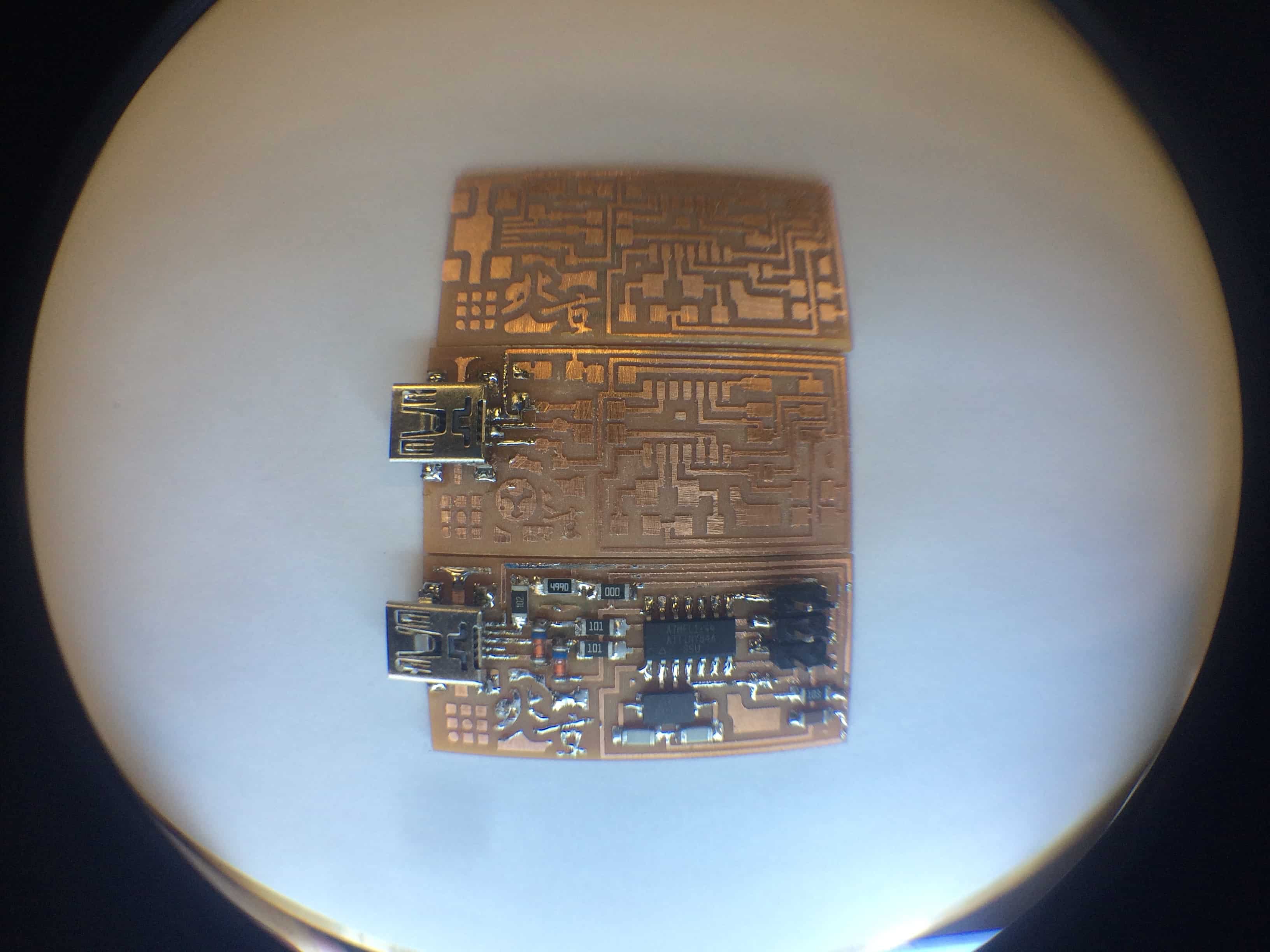
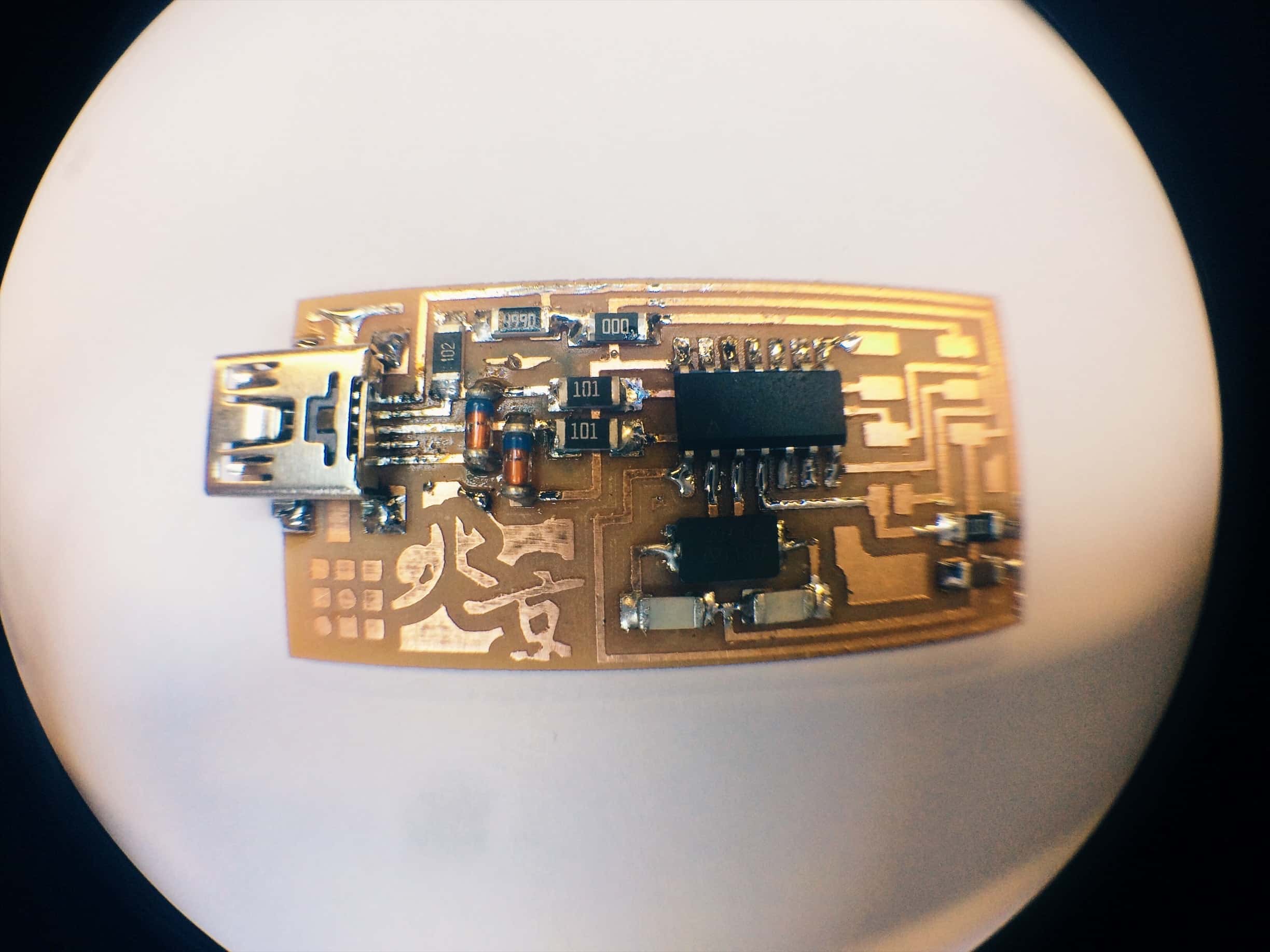
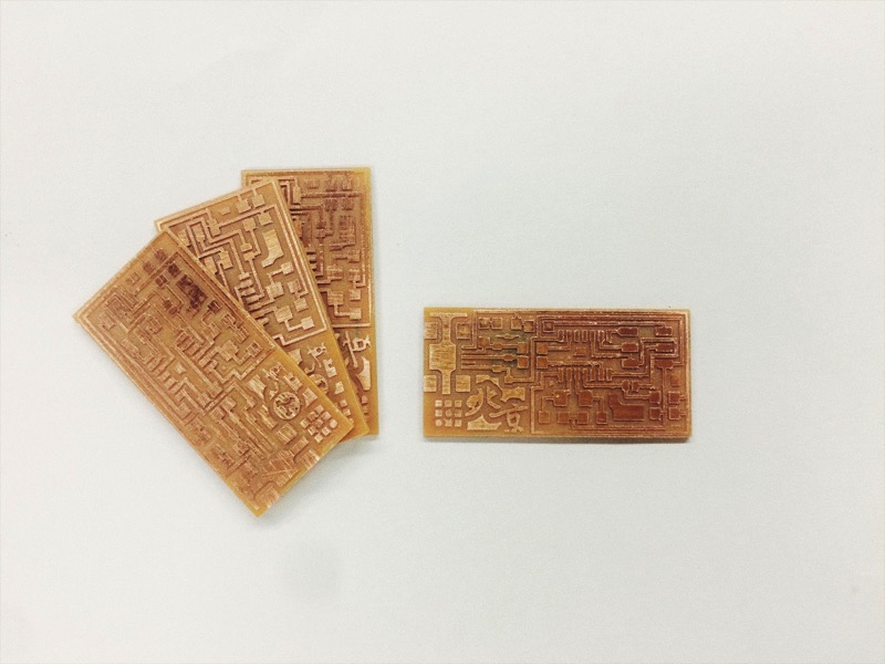
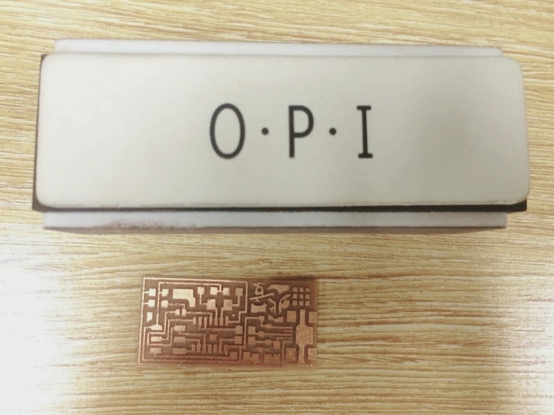
Finally, polish!!!you should polish pcb with one direction and flat. Don't over scratch any copper circuit. I finally made 2 version of this board the difference are between the logo.
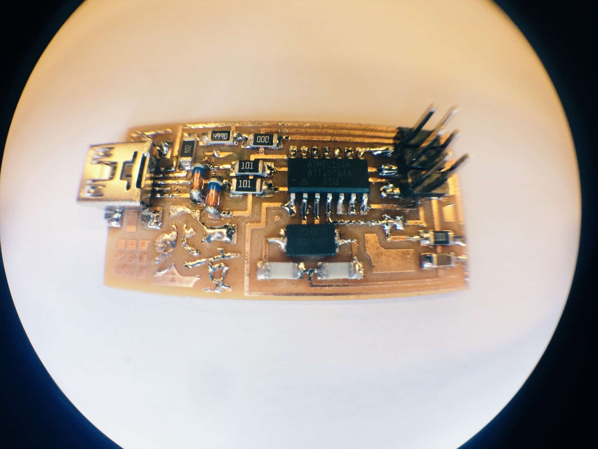
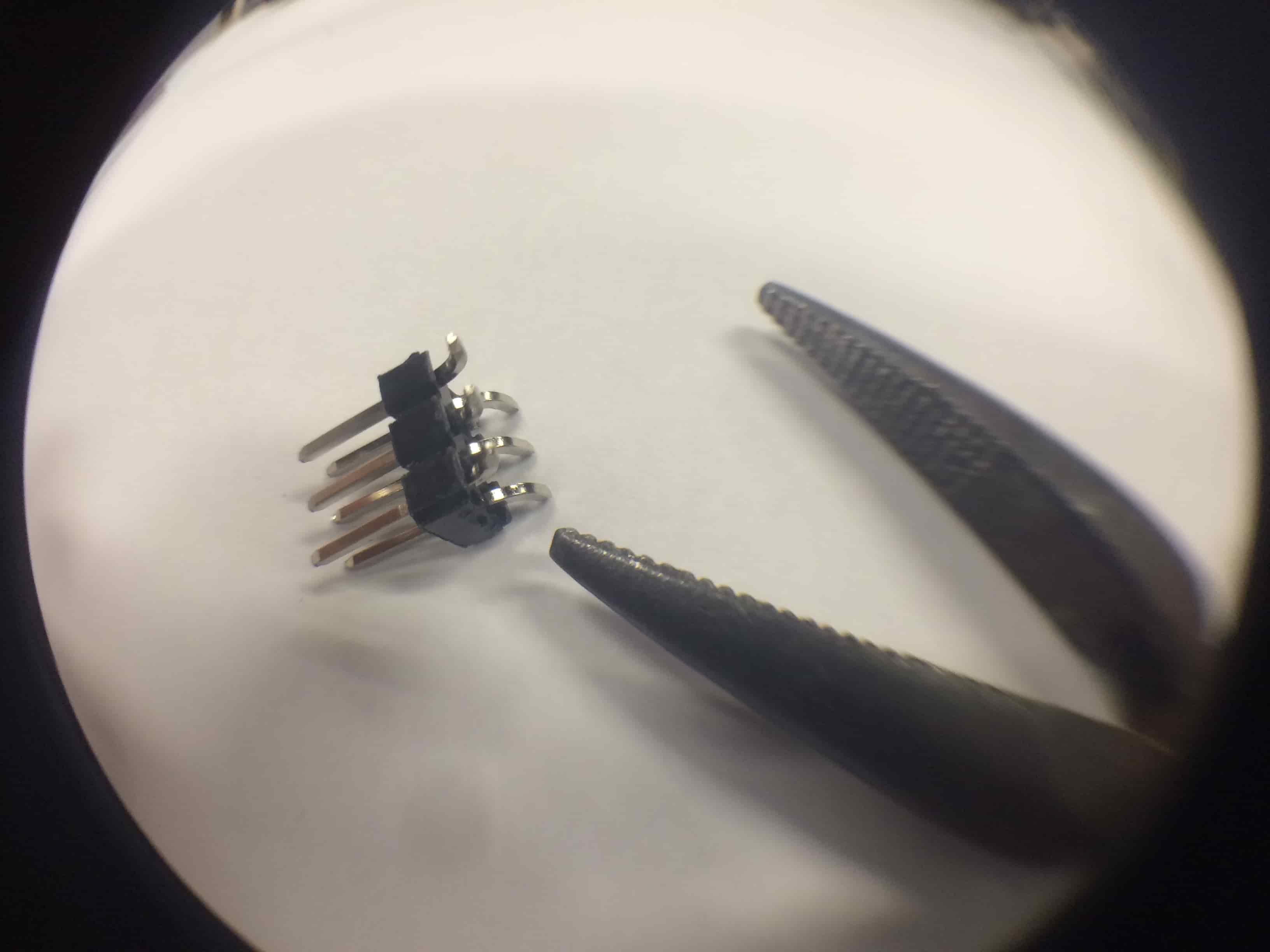
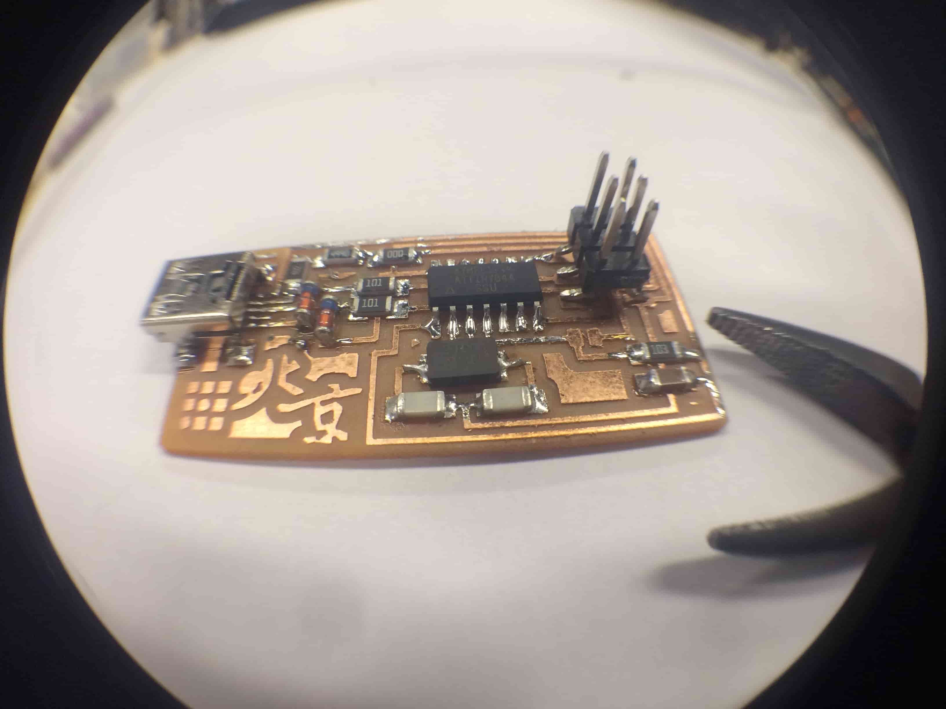
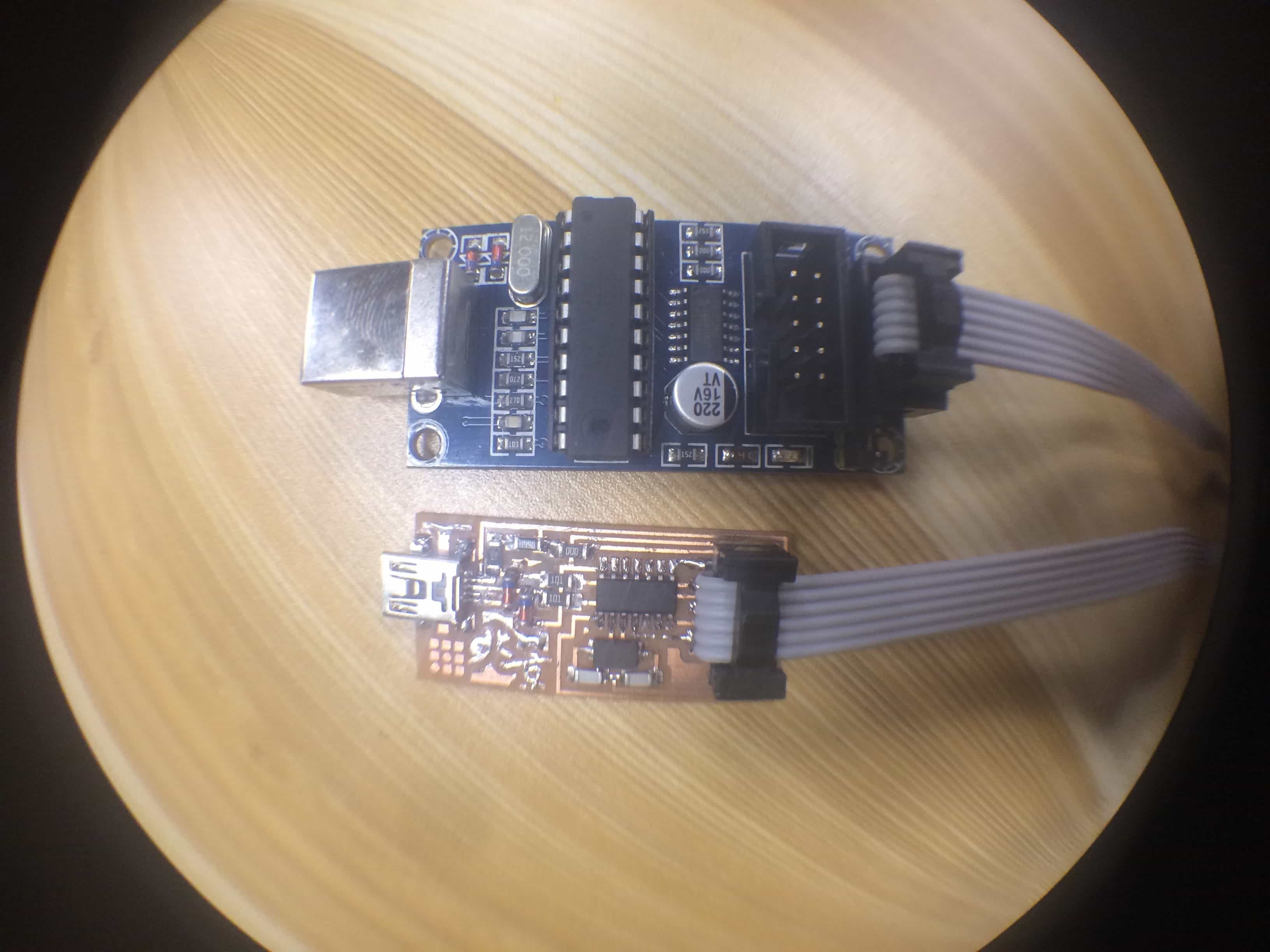
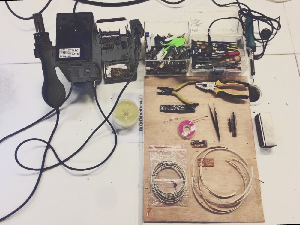
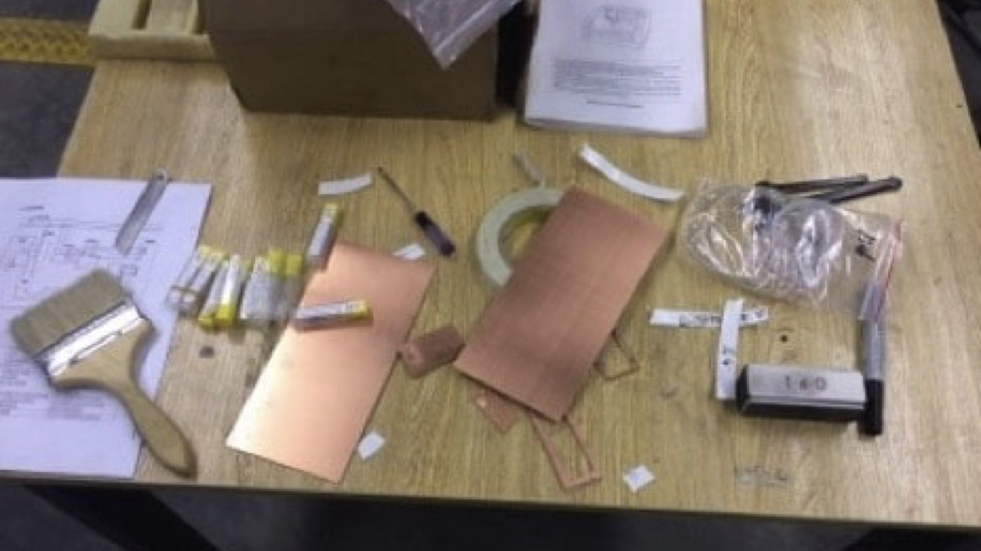
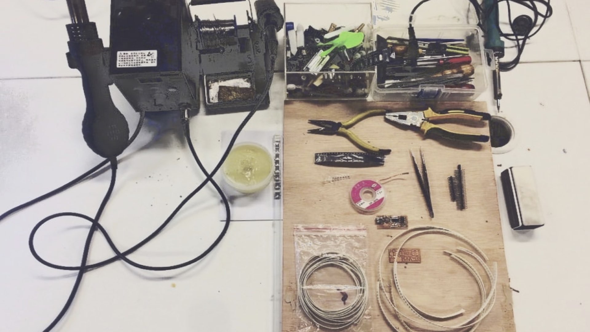
I was sick badly in that time, waste 1 week in a hospital. I really left the schedule behind Actually I even start soldering in my sickroom and this is how I get this photo on right photo in below is all the materials that I used. Then board diagram that I followed.
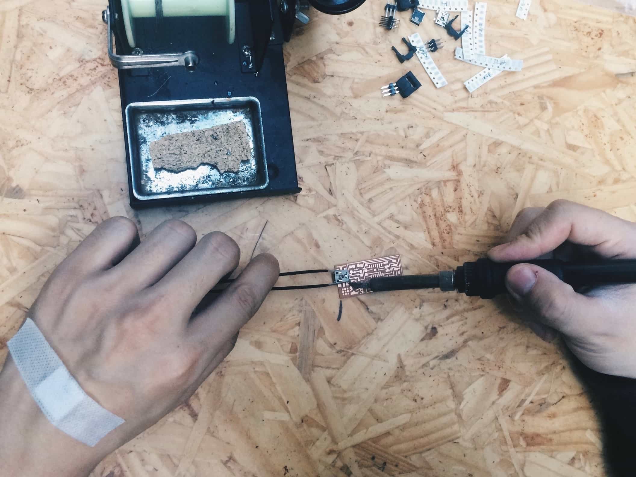
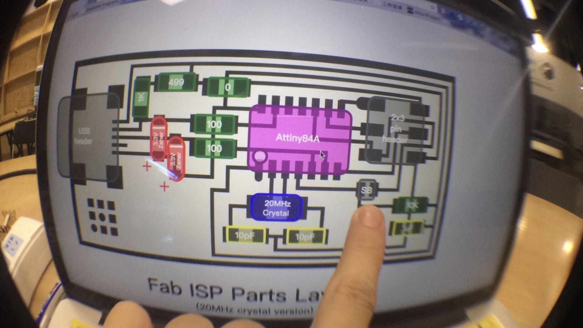
Solder the Mini USB Header first . Solder the micorcontroller second . Solder the Crystal and capacitors . Solder 1k resistor . Solder two Diodes, attation please the diode has polarity. Solder Jumpers . Solder 6 pin programming header .