DESIGN
First of all, I downloaded Autodesk Eagle and Fab library. I unziped the fab library to the right folder, which in mac is "/Applications/EAGLE/lbr/". Then I tried to create my first schematics file following the steps below:
- Opened Eagle
- Add fab library, make sure it is in use
- Create a new schematics file
- Add my first component ATTINY44-SSU
- Repeat the process and add other components
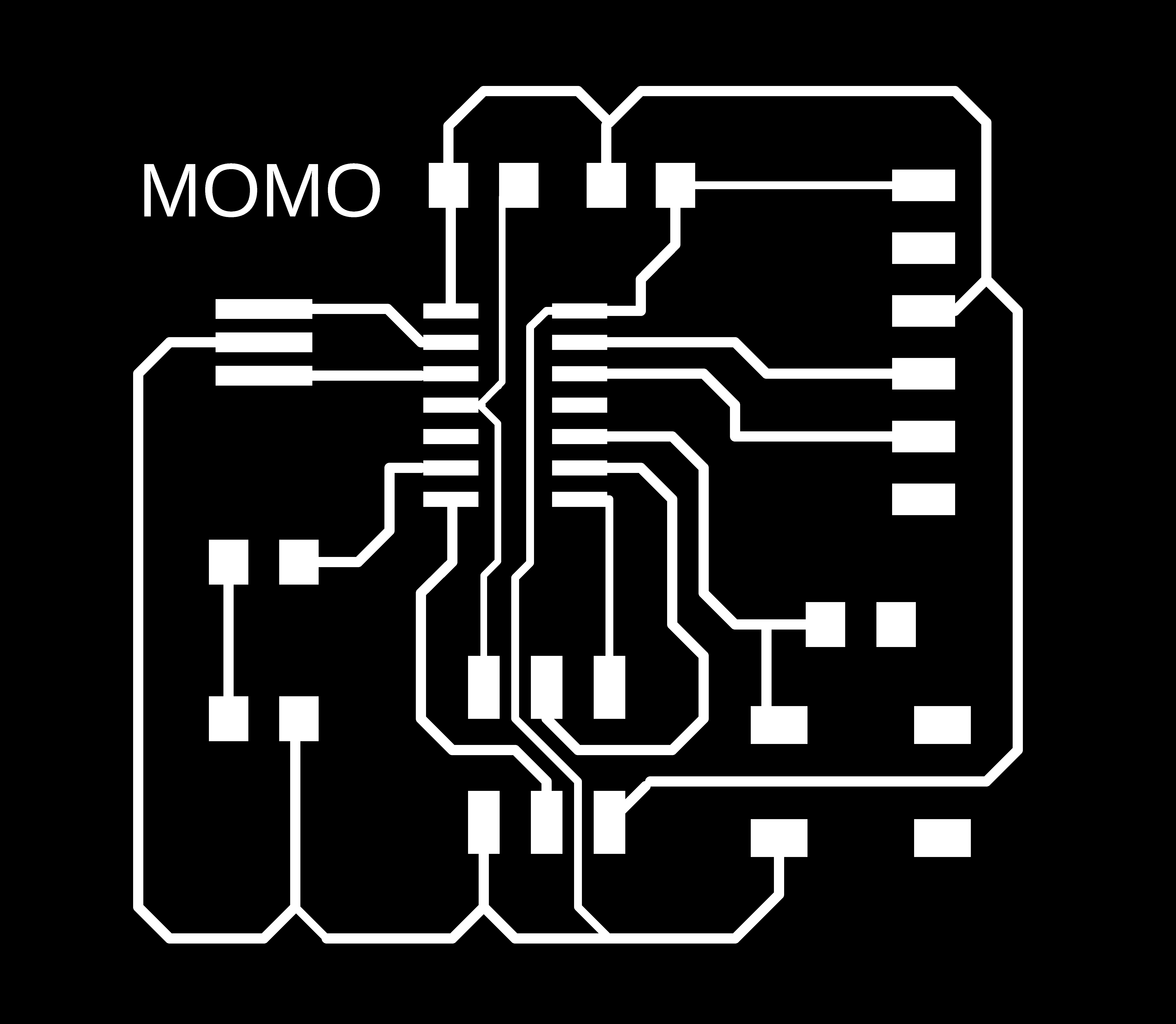
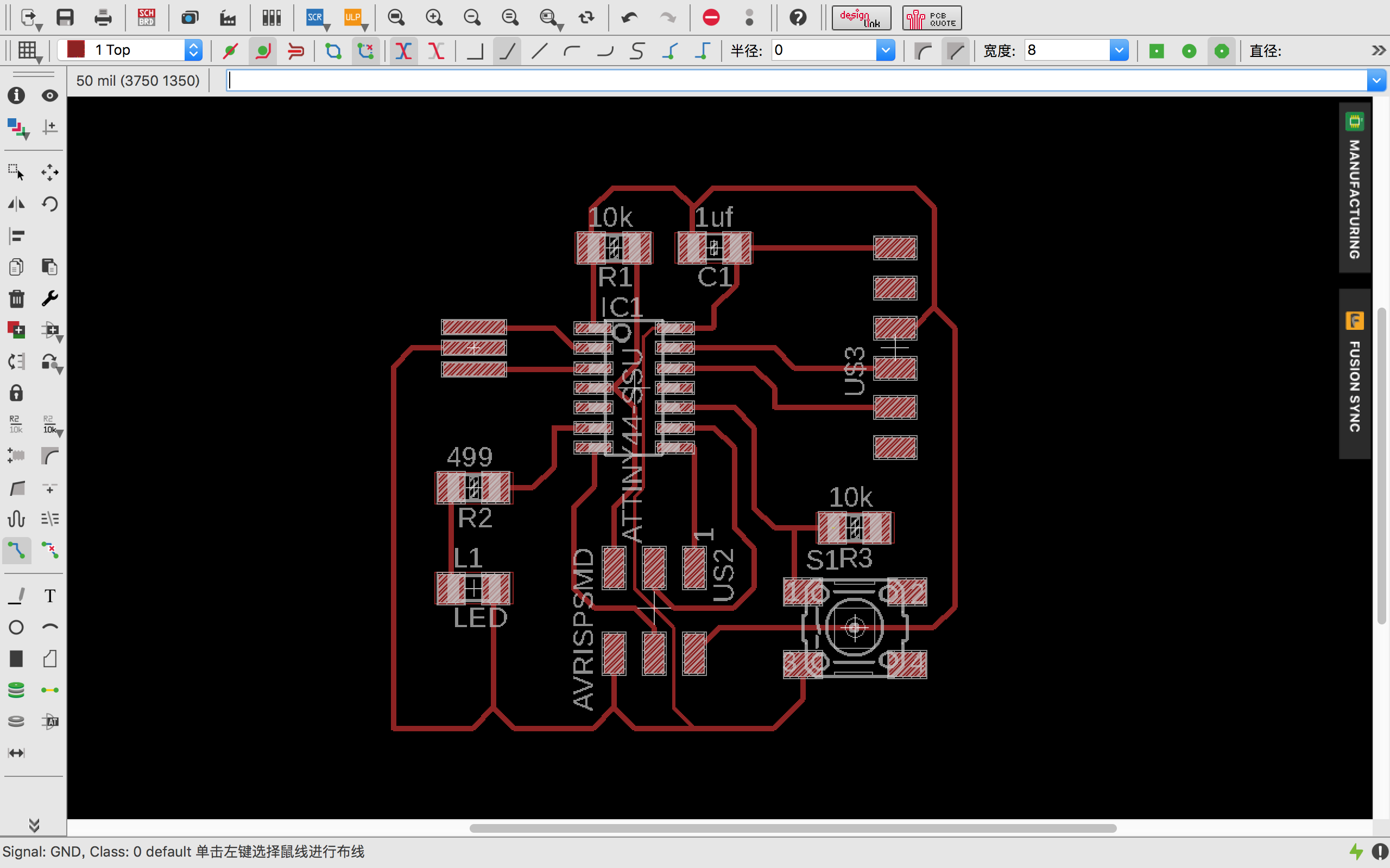
Next, I realized that I should have created a project with both schematics file and board file. Since the schematics and board work in parallel, it is better save both in the same folder and keep them sync all the time. All the components necessary for this assignment are listed below. With placing all the components on the schematics file, I tried to generate PCB route by using Eagle's autorouter function and got my readt-to-go file after some manual adjustments.
- 6-pin programming header: for programming the board
- microcontroller: attiny44
- FTDI header: powers the board and allows board to talk to computer
- 20MHz resonator: external clock
- button, LED, ect.
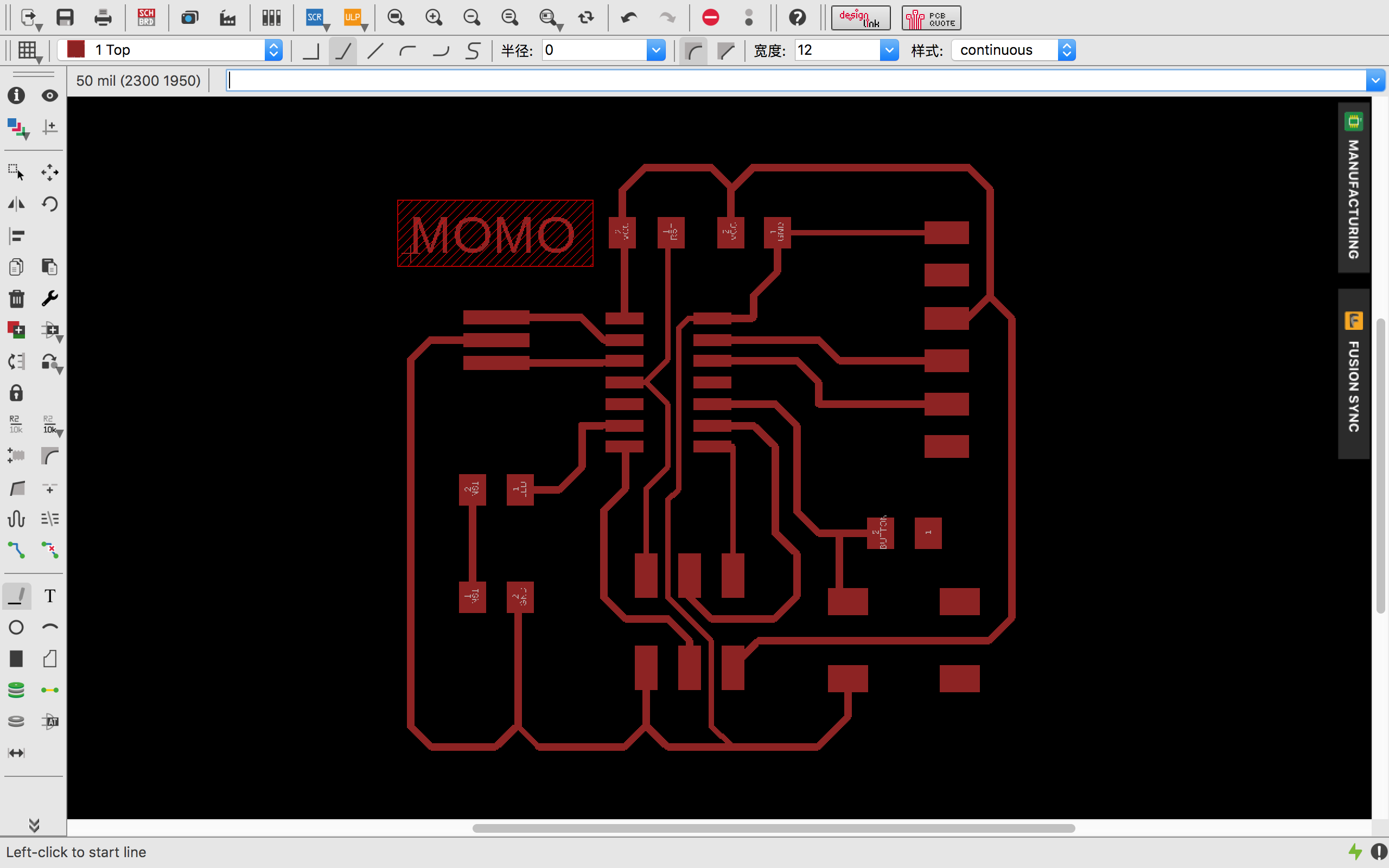
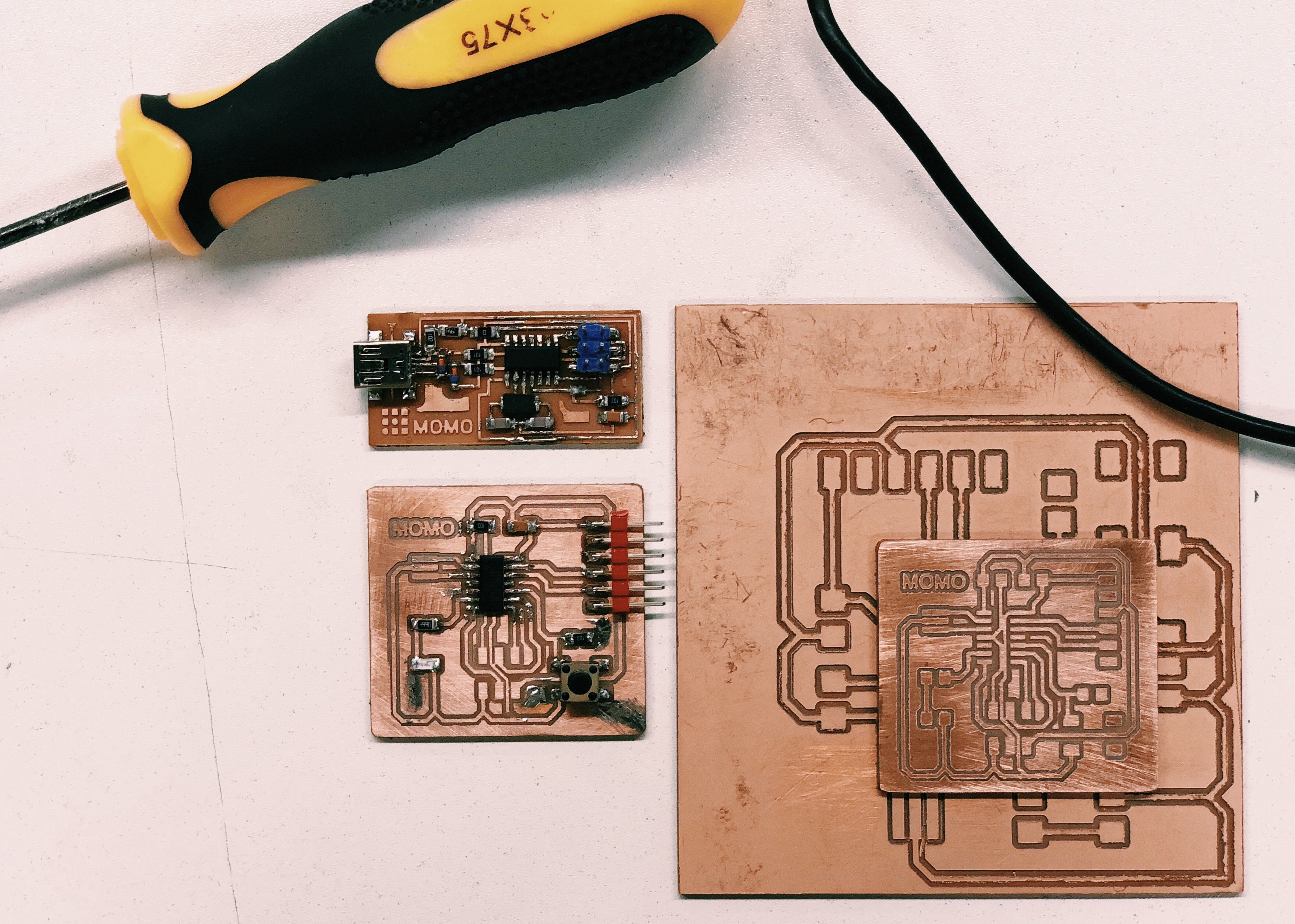
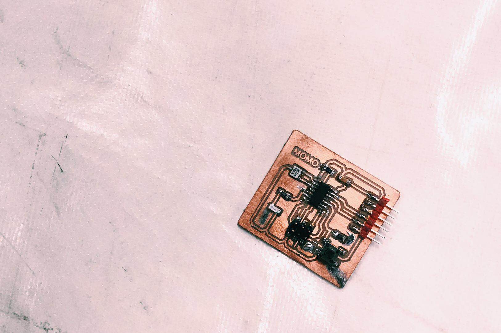
MILLING & SOLDERING
The final interior and trace file can be seen as below. While using Fab Modules to generate .rml files, you should pay extra attention to dpi! It seems we should be filled as twice large as we put in Eagle, otherwise we will get a XXXXL circuit board.