
Feed Rate = Spindle Speed (RPM)* Number of Flutes * Chip Load (inches) = Spindle Speed * Number of flutes * Chip Load = Answer inches/min
Use a plunge rate of 50% or less of the feed rate.
The group assginment was to test the CNC Router available in our lab, using a variety of settings, mainly speeds, feeds, and toolpaths. To achieve that, we constructed the same design using various settings and checked the differences in between.
So the objective of this week is to get introduced to Computer Controlled Machining and to learn how to use and operate the big CNC machine, mainly the one used to produce big parts.
CNC Machining is the process used in the manufacturing sector that involves the use of computers to control machine tools. Those tools include lathes, mills, routers and grinders.
In this section, we will learn on how to operate the CNC Router Machines.
There are many technologies and brands nowadays that are considered to be under the umbrella of CNC Routers. Among those are:
In order to understand the basics of CNC milling and machining, an intensive research was performed to discover all the variables that affect the CNC machining process.
There are many components that must be taken into consideration when CNC machining, and those mainly are based on the material undergoing machining, the tools used, and the machine itself.
In this section we will discuss the following topics that affect the process of CNC Machining and the final product, and describe how they are connected:
You can find more details on Makezine
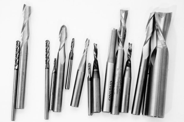
To begin with, there are different tools that are used during the Machining process, each having a specified job. The main three different tool types available are:
In addition to that, there are many specifications related to tools that vary from bit to bit.Those are affected by the project type, material being cut, and the desired surface finish. A detailed discription of those specifications will be mentioned below. Among those specifications are:
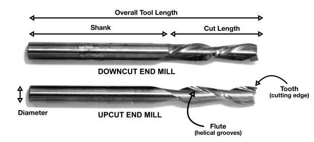
The image below illustrates the different parts of a bit showing the Diameter, Shank, Length of Cut, Overall Tool Length, Teeth, and the Flute.
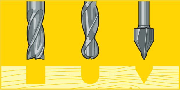
Concerning the Tip Shape of the End Mill, there are many different tip shapes that are designed for particular purposes. The most common shapes available are the following:
The image below illustrates the different tip shapes of a bit.
Concerning the material, you should choose a bit made for the material of your choice. Many manufacturers make bits especial for your material of choice. Bits for hardwood are designed to leave a clean edge. Bits for plywood and laminates are designed so they will not mangle the outer veneer layers. Bits for plastics are designed to avoid excessive melting. Aluminum cutting bits are designed to clear chips efficiently to avoid rewelding (heated chips getting fused to the hot cutting tool). Many bits can be used for multiple applications so you do not need to buy 30 bits right away if you are in the prototyping stage of your project. A good all purpose bit is a 2-flute up cutting spiral bit.
There are many router bit material available and here are some of them:
You can find more details on CNC Router Bit Basics.
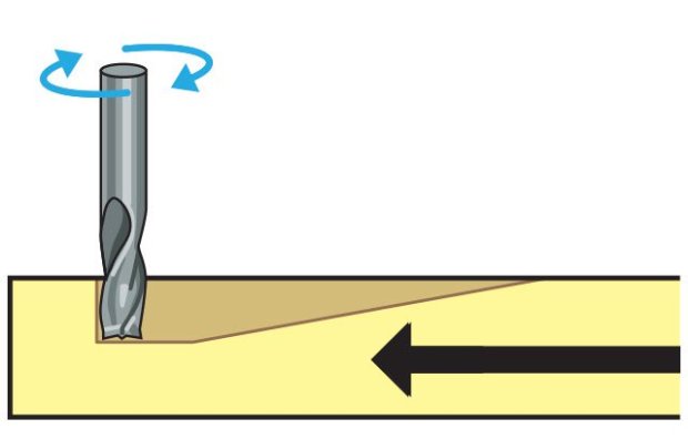
A CNC router spins a cutter clockwise. The helical direction of the flutes as they wrap around the tool determine if chips are ejected towards the top or bottom of the workpiece. True to their name, upcut mills eject chips towards the top of the workpiece, producing a cleanly cut bottom surface. The downside is possible surface splintering or “tearout” on the top surface as the chips are ejected upwards.
Upcutting bits mounted in a CNC pull chips (and your material) up and away from the table. They are great at clearing out chips from your cuts to avoid overheating your bits. They excel at making cuts all the way through material since they just slightly lift the material and scraps up into the end of the bit. Because of the upcutting action, these bits have a tendency to splinter the top surface of sheet goods like plywood and melamine coated particle board. You also need to be very sure that your material is securely held down to the table so the bit doesn't lift it from the table and chuck it across the room.
Downcut tools do the opposite, producing a smooth upper surface. They are ideal for pieces that have been previously engraved or v-carved and cannot be flipped to hide tearout. In addition, as downcut mills pack the chips into the cut path, they can be used instead of tabs to hold down a workpiece and keep it from moving. Downcutting bits press chips and material back into the cut and into the table. The downshearing action of these bits do a fantastic job of preserving your material's top surface. Since the chips are forced down into the cut, these bits should never be used to drill holes. The friction of the bit against the compressed chips is enough to melt plastics and start wood on fire.
A third option called a compression or up-down bit offers some of the benefits of both up and downcut bits. The bit is a standard downcut bit until you get to the tip. The direction of the cut is switched making the tip an upcutter. This means that you can cut through materials like plywood and you will get a clean edge on both sides. The top is shear down, the bottom is pulled up. Compression bits are never to be used to drill holes. Once the bit has been plunged beyond the direction change, the chips have no way to escape and get compressed creating an extreme amount of friction and heat. Compression bits are a little more expensive because of the complicated manufacturing of the cutting edge but they are my goto bit for nearly all of my wood cutting.
You can find more details on Guide to CNC bits.
Flutes are the helical grooves that wrap around the sides of the end mill. Each flute has a single tooth with a sharp cutting edge (although there can be more than one) that runs along the edge of the flute. As the tooth cuts into the wood, each flute whisks away a small section or `chip`. The fewer the flutes, the more material that is ejected with each tool rotation. The overall cutting depth should never exceed the length of the flutes on an end mill. If cutting deeper than the length of the flutes, the tops of the flutes will be blocked and chips won't clear, building up heat and reducing tool life.
Chipload is the thickness of a machined chip as cut by a specific tool type. This is simply the thickness of a chip which is formed during the machining of material. Chipload is important because the proper size chip will carry away heat, promoting long tool life. When the chip is too small, heat is transferred to the cutting tool causing premature bit failure. Too high of a chipload will cause poor edge finish, and transfer cutting load or thrust to the part, possibly causing it to move. A bit in good condition and running at recommended loads will be at room temperature when a cut is finished.
More flutes create a smoother surface finish, while fewer flutes remove material fastest, but make rougher cuts. Proper chipload is important because chips dissipate heat. Hot cutters can lead to suboptimal results, including burned wood, a poor edge finish and dull tooling.
So, in conclusion:
There are many tables that help you choose the chipload of the job you want to do, which will be needed to calculate the speed of the router. The image below represents one of the chip load charts available online.

Please note that those represent a specific kind of milling bit. Specific loads for your tools can be obtained from your router bit manufacturer.
The speed at which we move a cutter across the material is called the `feed rate`. The rate of rotation is called the `speed` and is controlled by how fast the router or spindle turns the cutting tool. Both feed rate and spindle speed will vary based on the material being cut. A general rule of thumb is that you want to move the tool through the material as fast as possible, without sacrificing surface finish. The longer the tool rotates in any one place, the more heat that builds up. Heat is your enemy and can burn your material or radically decrease the life or your cutting tool. Feed rate vs spindle speed: Spindle speed that is too fast paired with a slow feed rate can result in burning or melting. Spindle speed that is too slow paired with a faster feed rate can result in dulling of the cutting edge, deflection of the end mill and possibility of breaking the end mill. A good strategy when selecting a cutter is to attempt to balance feed rate and spindle speed by performing two passes on the work piece. The first pass, called the roughing pass, can be done by using an end mill that will eject a large number of chips at a high feed rate. The second pass, called the finishing pass, then won’t require as aggressive of a cut and can provide a smoother finish at a high speed.
Chipload refers to the physical size of the chips the bit creates when making a cut. Higher feeedrates produce larger chips. Higher tool rpm produces smaller chips. If your chips are to large, you risk breaking your bit. If your chips are more like a fine powder, you are probably dulling your bit. It's a balancing act but start with the manufacturers recommended settings and adjust from there.
Chipload = Feedrate / [RPM x number of flutes]
The nominal surface speeds used for various material are shown in the image below.

Here are some equations you need to know to calculate the spindle speed and the Feed Rate during any job in mind.
Feed Rate = Spindle Speed (RPM)* Number of Flutes * Chip Load (inches) = Spindle Speed * Number of flutes * Chip Load = Answer inches/min
Use a plunge rate of 50% or less of the feed rate.
Many settings can change that control the toolpath of the tool. Among those settings are the following:
Ramp is used to reduce the tool breakage and stress on the material being cut. It occurs by ramping the end mill slowly into lateral cuts, where your tool moves in an XZ or YZ 3D incline into your material to reduce stress on your bit when plunging.
So the next step is to test the different outputs we get by variating the settings of the machining process. In this section we will test the alignment of the Shopbot we have in our fab lab, and then test the various outcomes we get when we change the speeds, feeds and toolpaths. To achieve that, we prepared various test files that we used to perform those tests.
Getting to the actual testing, first we had to identify our material that would be cutting and the bit we are going to use.
Based on our choice, we got the Chip Load Data from the ONSRUD Website. It has specified that the chipload should be between 0.004 and 0.006 so we had room to adjust our variable settings as long as we were in the specified scope.
We decided to go with a chiprate of 0.005 which is halfway in between and adjust the spindle speed and feed rate while maintaining the chiprate based on the equation stated above Chipload = Feedrate / [RPM x number of flutes]
We chose to start with the first test which is variating the Feeds, Speeds, and Toolpath and check the difference between the outputs. In the first test we followed 3 Steps of 1 x D (Cutting Diameter of Tool).
So the Chiprate is a constant 0.005: Chipload = Feedrate / [RPM x number of flutes]
In addition to the Feed and Speed Settings chosen, each setting was tested two times. The first time having the Climb Toolpath and the second having the Conventional Toolpath. we did two different passes The image illustrates the raw result. We noticed that the Setting 2 Climb had the best result in relation to our bit and the material used, so we went on with this setting to achieve our final designs with the individual assignment. It is safe to say that all results were very similar, but the second had the best results as in finishing.

We also did another test with one pass instead of 3. For this test we had to recalculate the chip rate. According to the supplier and professionals in the industry, the Chiprate is reduced to 50% at a depth of 3 x Cutting Diamter. So the new Chiprate used was 0.0025.
Saying that, the Setting used for this test are the following: Chiprate = 0.0025; RPM = 14,000; Feed Rate= 35
We noticed that the outcome has a rougher surface than the test done with 1xD, however it is a fast way to cut when the quality is not an issue.

After choosing the best settings for the PlyWood we are using along with the Tool we have, we went on to do the squareness test. For this test a test file was prepared having an external square, an internal rectangle and two circles. The external square and one of the circles were cut following the extenal path. On the other hand, the rectangle and the other circle were cut following the internal paths. After the test was done, a comparisson was done between the original design and the outputs. Some minor differences were deduced between both. The external paths made a slightly bigger output. On the other hand, the internal path made slightly smaller outputs.

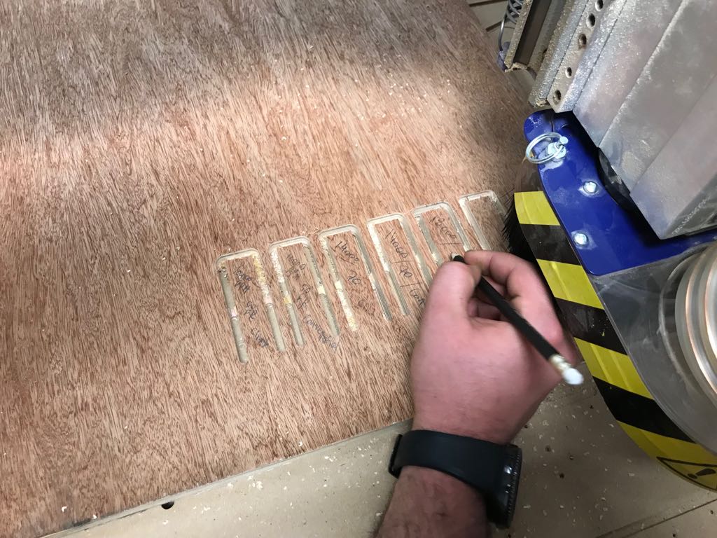
After doing all the previous test, we went on to make a press-fit test, to check which is the best width we should use for the joints so we have a press-fit connection. The Board thickness is 14.6mm. So we choose three different dimensions:
Based on this test, we found out that the 14.8 mm had the best fitting result.

In the previous test, the fitting were not perfect as they could not go through to the end, as the drilling bit cannot achieve a 90 degrees. Saying that we used another technique known by the t-bone technique. The same test was done but this time a circle having a dameter slightly bigger than the milling bit diameter was placed at the 90 degree corners. The image illustrates our results. Perfect fitting was achieved with the used t-bones.
