For the machine design week we had one assignment, which is to build a machine from scratch using the skills we have been aquiring/refining since the beginning of FabAcademy. The idea did not come about with ease, being a team of two we had to narrow down the design to something feasible and doable in two weeks. However we both are ambitious enough to take on bigger projects no matter the complexity as long as it falls within the limited time frame that we have which is two weeks.
Brain Strorming
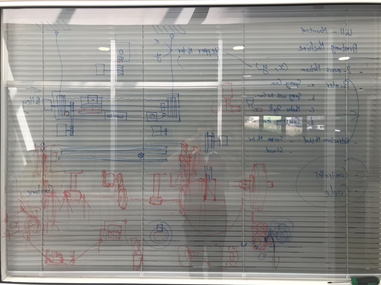
So the first step in this project was to design our machine after many brainstroming sessions. We had many different ideas that could achieve the same result. However, as all brainstorming sessions, ideas changed rapidly and we tried our best to keep the idea feasible and doable in one week.
So, since most projects were plotting machines we decided to go with something similar, only we were also inspired by the digital LED screen pixel refresh, so the Idea was to build a machine that had is a combination of both. We would have one large panel that would cover the width of the face of the wall we want to paint on (x axis) and another mecanism that would bring it up and down the length of the wall (y axis). As for the Z it would be a 5x5 square that has foam, or a material that would 'drink' the ink that would be filled in the container, guided by the xy axis and pushed on to the face of the wall to mark the 'pixel'
Mechanical Design
Design
The various parts that were mainly included in the machine design were the following:
Rack and Pinion system that will achieve the horizontal left and right motion
Frame of the machine that is designed to be made of 1cm thickness MDF and assembled using nuts and bolts
Pulley system that will achieve the vertical up and down motion
Coloring Tank that will carry paint inside it
Paint Applicator which constitutes of a tube that moves along one axis, and pushes the painting head on the painted surface
Main Plate that will carry the paint tank, the applicator, and the stepper motor connected to the pinion. This plate with the rack and pinion system is what provides the horizontal motion
Front Wheels that will guarantee a constant distance betweent the machine and the surface as they roll on top of it
Below, you can see the process of designing the machine.
Manufacturing
The main frame of the machine and the various parts that formed the pulleys were produced using the CNC milling machine, Shopbot. The DXF files were extracted from the sketches of the Fusion 360 design and then inserted on Vcarve to produce the g-code, which will then be used to machine the parts. All the parts were milled from a 1cm thickness MDF sheet.
Other parts required high precision in the production process, mainly the rack gears, as they were hard to produce using cnc milling due to the small distance between the rack teeth that cannot be covered by the milling bit we have in the lab. The rack was produced from a 1cm thickness MDF plate. The other part that was laser cut was the main plate that will carry the painting kit. This part was cut from a 5mm thickness acrylic sheet.
Lastly, various parts were produced using 3d printing, mainly the 3d parts that we were planning to produce in plastic and flexible material:
Silver PLA was used for the wheels that will carry the main plate on the rail, the printing head and the tube.
Red PLA was used for the main tank that will carry the painting material.
Green PLA was used for the support that will carry the Front wheels.
Black PLA was used to print the servo motor stand and pulley.
Black NinjaFlex, is the fexible material used to print the front wheels to provide traction with the painted surface.
Tough Resin was used to print the pinion gear.
Assembly
Before final assembly of the machine parts, the first step was to make sure that they fit altogether, in order to make final edits before assembling. All the different parts were tested together, to make sure that they will achieve the job they are meant to do. All parts fitted perfectly together, but the pinion gear was getting stuck between the guiding plates. The reason for that was the MDF plate used was not a perfect 1cm, in fact it was 0.95 cm. So we had to do some edits on the pinion gear and re-print it so it can move loosely.
Next, we assembled all parts and we tried to test them move as they are supposed to move before starting with the electronics and control part. As a first step, we made sure that the main mounting plate, that will carry the paint applicator, moves freely on the horizontal axis, on the designed rail. It worked.
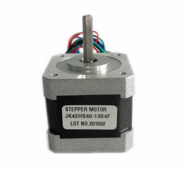
Next we assembled the pulley system using the CNC milled pulleys and chasis plates, and a set of standard GP2 pulleys and belt. In addition, guiding rods of diameter 8mm were used as the axis for the main pulleys that will carry the pulling cable. A 20 tooth pulley was fixed on the axis of the Nema 17 stepper motor, and a 40 tooth pulley was fixed on the axis of main pulleys. This would achieve a 2:1 gear ratio between the source and the driven pulleys, thus achieving a higher torque.
After assembling all parts of the machine, and making sure that each part does its specific job, the next step was to make sure that the whole system works correctly altogether before installing the electronic components and working on the control part.
The video below shows how the system worked by moving it manually by hand. Both the horizontal motion and the pulley system worked according to the designed concept. The next step is to start controlling it and checking if it works for real.
Machine Control
For the machine control, we decided to have the machine controlled in two ways:
The first one would be with the help of a joystick, and
The second would be by the generation and application of the g-code.
Electronic Components
The electronic components used for the automation of our machine were the following:
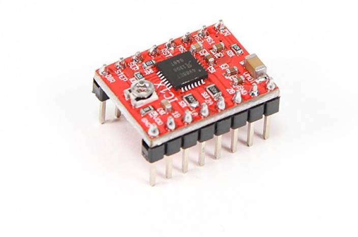
2 x A4988 stepper drivers, in order to be able to control the stepper motors
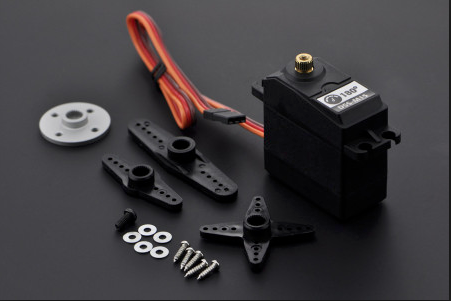
1 x DSS-P05 servo motor, in order to control the z-axis
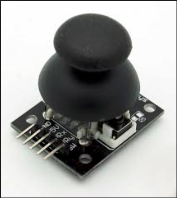
1 x Arduino joystick, for the first option of the system control
Joystick Control
Below, you can see the code that was used to control the machine with the use of the joystick.
#include <Servo.h>
//Servo
Servo myservo;
int pos = 0;
//Joystick Control
#define Joy_switch 13
int UD = 0; //js
int LR = 0; //js
int IUP=A0;
int ILR=A1;
int MID = 10; // 10 mid point delta arduino, use 4 for attiny
int LRMID = 0;
int UPMID = 0;
// Connections to A4988 (Stepper Driver)
const int dirPin1 = 2; // Direction
const int stepPin1 = 4; // Step
const int dirPin2 = 7;
const int stepPin2 = 8;
// Motor steps per rotation (Stepper)
const int STEPS_PER_REV = 200;
void setup() {
//Stepper Setup
pinMode(stepPin1,OUTPUT);
pinMode(dirPin1,OUTPUT);
pinMode(stepPin2, OUTPUT);
pinMode(dirPin2, OUTPUT);
//Servo Setup
myservo.attach(9);
LRMID = analogRead(ILR);
UPMID = analogRead(IUP);
pinMode(Joy_switch, INPUT_PULLUP);
//pinMode(MID, INPUT);
}
void loop() {
//Read Joystick
UD = analogRead(IUP);
LR = analogRead(ILR);
// UP-DOWN
if(UD < UPMID - MID){
// Set motor direction clockwise (HIGH)
digitalWrite(dirPin1,HIGH);
// Spin motor quarter rotation slowly
for(int x = 0; x < (STEPS_PER_REV / 4); x++) {
digitalWrite(stepPin1,HIGH);
delayMicroseconds(2000);
digitalWrite(stepPin1,LOW);
delayMicroseconds(2000);
}
}
if(UD > UPMID + MID){
// Set motor direction counterclockwise (LOW)
digitalWrite(dirPin1, LOW);
// Spin motor quarter rotation slowly
for(int x = 0; x < (STEPS_PER_REV / 4); x++) {
digitalWrite(stepPin1,HIGH);
delayMicroseconds(2000);
digitalWrite(stepPin1,LOW);
delayMicroseconds(2000);
}
}
// Pause for one second
//delay(1000);
// LEFT-RIGHT
if(LR < LRMID - MID){
// Set motor direction counterclockwise (LOW)
digitalWrite(dirPin2,LOW);
// Spin motor quarter rotations quickly
for(int x = 0; x < (STEPS_PER_REV / 4); x++) {
digitalWrite(stepPin2,HIGH);
delayMicroseconds(2000); //changed to high was (1000)
digitalWrite(stepPin2,LOW);
delayMicroseconds(2000); //changed to high was (1000)
}
}
if(LR > LRMID + MID){
// Set motor direction counterclockwise (HIGH)
digitalWrite(dirPin2,HIGH);
// Spin motor quarter rotations quickly
for(int x = 0; x < (STEPS_PER_REV / 4); x++) {
digitalWrite(stepPin2,HIGH);
delayMicroseconds(2000); //changed to high was (1000)
digitalWrite(stepPin2,LOW);
delayMicroseconds(2000); //changed to high was (1000)
}
}
// Pause for one second
//delay(1000);
//Joystick Switch
if (!digitalRead(Joy_switch)) {
// Servo sweep 0 - 180 and back
for (pos = 0; pos <= 180; pos += 1) { // goes from 0 degrees to 180 degrees
// in steps of 1 degree
myservo.write(pos); // tell servo to go to position in variable 'pos'
delay(15); // waits 15ms for the servo to reach the position
}
for (pos = 180; pos >= 0; pos -= 1) { // goes from 180 degrees to 0 degrees
myservo.write(pos); // tell servo to go to position in variable 'pos'
delay(15); // waits 15ms for the servo to reach the position
}
}
}
Below, you can see a video of the control of the two motors and the servo with the use of the joystick.
G-Code Control
The second option was the complete automation of the machine by the use of a G-code. The Gcode was generated on Fabmodules and sent to the Arduino that had the GBRL software uploaded and then using a software called Universal g-code sender (by UGS) that would feed the commands to the machine. This option is still not fully functional as it still needs a lot of calibration on the g-code. Yet, below is a simple test with the process of running a Gcode:
Download the Universal Gcode Sender (UGS) to be able to generate the code and run the control pannel. Many versions are found on Github. In our case, we used UGS version 1.0.9 and GBRL version 1.1.
The downloaded file of the UGS platform would be a folder that contains several files. The UGS platform itself would be the .jar file.
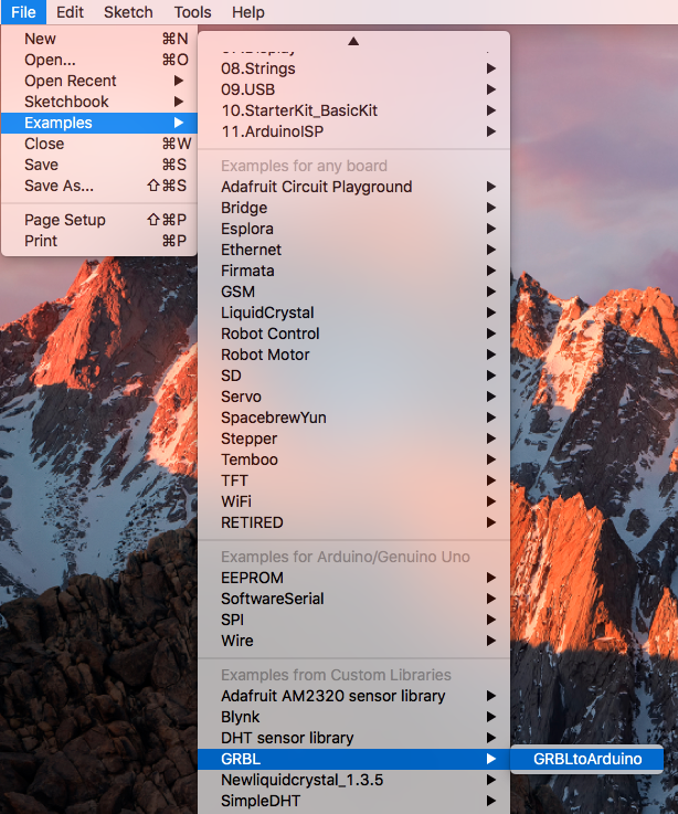
Then you need to download and import the Gcode library. It would be saved as an example in the arduino IDE under File/Examples/GBRL.
Upload the code/example to the Arduino. Do not Alter anything, the library is what contains the actual code and the process in the IDE is to run it.
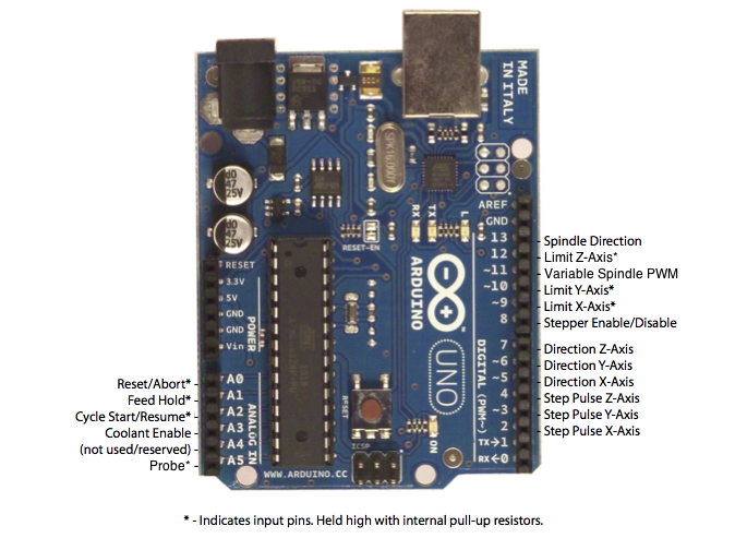
Make the connections between the stepper motor and A4988 stepper driver module shown below. Then you would need to connect the module Direction and Step pins to the Arduino. For this example I only used one axis which is the X. So the Step pin of the A4988 driver goes to PIN 2 of the Arduino and the Direction to PIN 5. The image below would show where the rest of the pins need to be to take full advantage of the Gcode and the project at hand.
Once you have all connections made, connect the Arduino to the PC and open the UGS software.
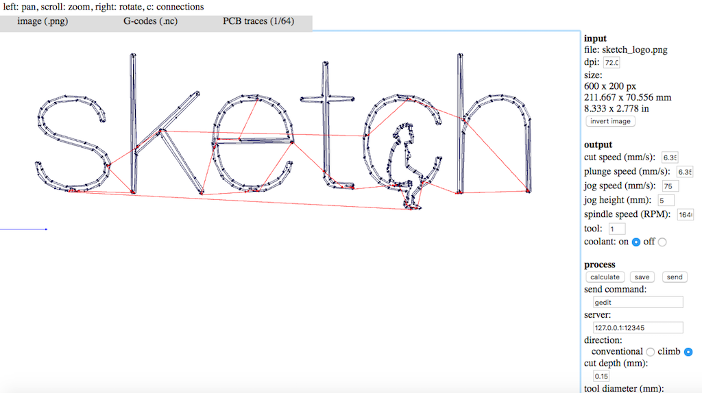
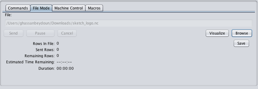
Using fabmodules, upload any monochrome(black white) png image and make out the traces to calculate and generate a Gcode. Then save the code onto your PC. I chose to save the file in .nc format and it worked.
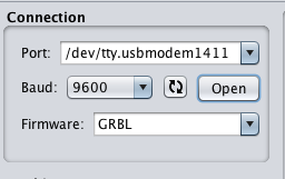
In the UGS platform, first select the port where the Arduino is connected and make sure of the baudrate; then click open. The UGS platform should now establish communication with the Arduino.
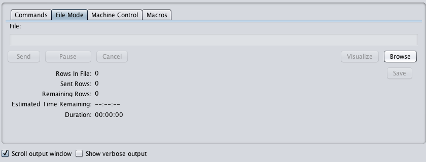
Now click on the file mode tab and use the browse button to upload the file that has been downloaded from fabmodules which contains the Gcode.
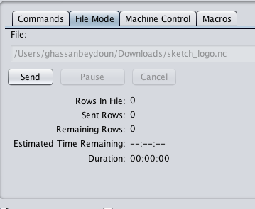
Once the file is uploaded to UGS, hit send and the process should start. You can also click the visualize button to see where at which stage the process is.