
Computer-Aided Design
COUNTDOWN
3D Design
For this week's assignment we had to draw a 3D Design on a 3D software of our choice. I experimented on 3 softwares, Solidworks, SketchUp, Fusion360. I ended up using Fusion360 as I am still a beginner with these and found it to be practical and user-friendly. Each tool has a brief description and demo of what it does and found this to be great. Although Solidworks seemed to give much more freedom with the designs, I went ahead and drew my first design on Fusion 360.
As for my first design I decided to go with something basic and familiar, where I could understand and implement all the components. I went for a small rigid box that is insulated/waterproof, has 2 hinges and 2 brackets to be able to lock. As for the insulation I only had an opening/carved to have a rubber chord/ O-ring around the inside edges to seal it. This box could be used for future projects that might need having electronic components stored safely. Ofcourse additional details should be added then such as holes to have the wires to connect exterior electrical components.
Designing
Step 1
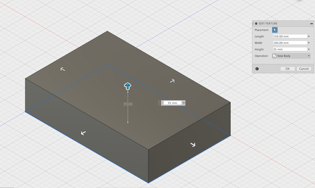
For the first step I just chose a plane to start sketching on then took the following steps:
- Created a rectangle
- Used the press pull tool under modify (I actually pressed the shortcut Q) To move it from 2D to 3D and have the first half of the box.
Step 2
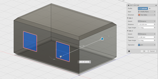
For the second step I started adjusting details on the box in the following manner
- Made 4 small rectangles on the sides of the box so I can attatch the hinges and brackets(locks) by choosing the face of the body (box) and creating a new sketch on it
- Again with the press pull tool pushed the slightly out so they would be a good basis for the add-ons as well as giving it more room to attach anything to its exterior
- I also used to Chamfer tool under Modify and applied it to the bottom edges of the box to give it some sort of design
Step 3
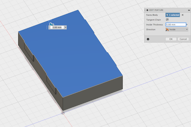
For this step I used the:
- Shell tool under Modify and made a hole inside the box to give its interior shape and left about 5mm thickness as the sides of the box.
- Used to Chamfer tool again on the inside edges of the box.
Step 4
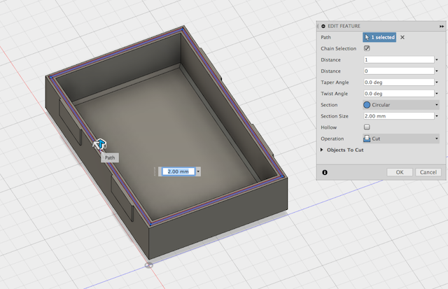
For this step I just created a carvature along the top edges of the box so I could put a rubber chord/ O-ring, for this I used:
- Pipe tool under Create and used drew it along the edges of the interior upper edges of the box
- In my case I went with a 2mm radius to get 4mm diameter rubber. These could be modified at later stages if found to be inefficient
Step 5
For this last step I copied the half box I created in the previous steps, in order to copy it:
- First right clicked on the body 1 section which refers to that box and clicked on the move/copy tab in the drop down options
- Then once copied I moved and rotated the copy of the original half box until it completed the second half (as shown in picture)
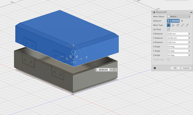
Now I have the box's outter and inner shape completed.
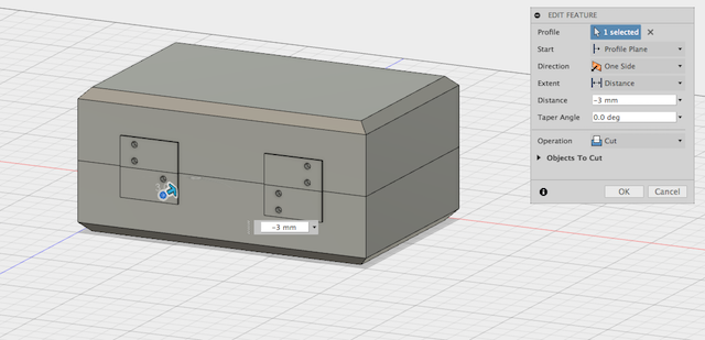
Step 6
For this last step I made holes using the press pull tool again to make holes for the other parts of the assembly which would be the hinges and brackets(locks) and will be shown below. Since I wanted the other parts to be assembled seperately so I can print them more effectively and adjust their designs if need be. The holes made in this step would be used to hold them in place more effectively.
Other parts for assembly
Other parts for the assembly include the brackets(locks) and hinges. In order to sketch these I basically used the same tools and commands I used for the box itself. Only two additional tools were used:
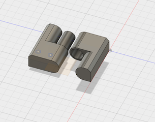
- First the Fillet tool, which is very similar to the Chamfer tool used above only it makes round edges instead of flat ones. I specifically used it for the hinges since there would be some rotation and thought it would be more efficient to have them as close to each other as possible and have the least possibility of friction.
- Another tool used was again the move/copy body tool, only this time I used it to move the hinges from point to point whereas I chose the inside point of the female part of the hinge and moved it to the top male part of the hinges to be able to test them and see that they are not blocking each other (shown seperate in the image below)
Parametric Design
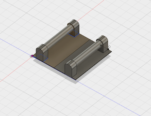
I decided to do the legs of the box (to give clearance from surface it is on)
Step 1
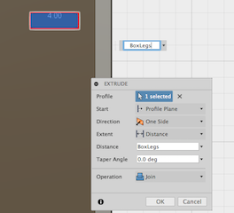
- First I had to create a "parameter"
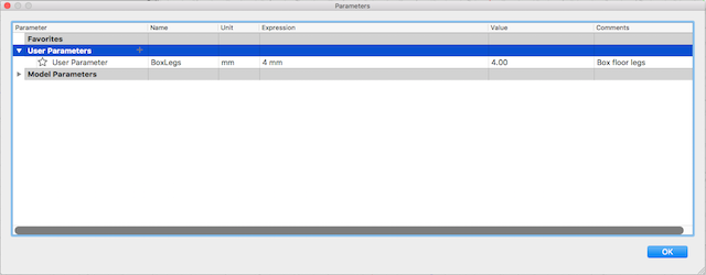
- Then Create a user parameter, I did it 4 mm as in the length of extrusion on the legs
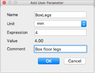
-
And Finally when the prompt to input the dimensions required I just had to type in the title of my created parameter "BoxLegs" and it automatically takes it as 4mm.
Hinges
Bracket Locks
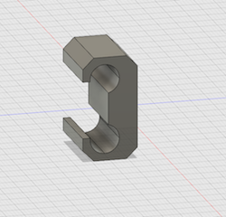
Bracket/Lock Fixtures
2D Design
For my 2D design, after thorough research I decided to use DraftSight because it seemed very effective and I actually was interested in the fact that I could use tools in a command line form. So I didn't have an elaborate design but I just used it to try it out for future projects.
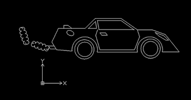
Below are the steps I have taken to accomplish the drawing (a VERY basic car):
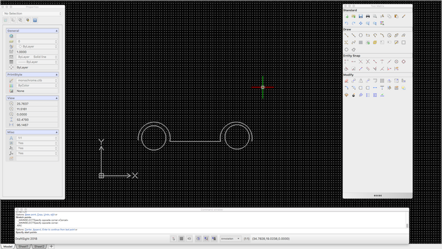
- Step 1:
I used the line and circle and spline tools to draw the undercarrier and wheels of the car
- Step 2:
I used the poly-line tool to draw the rest of the car including body, doors and windows
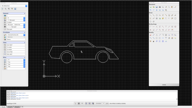
- Step 3:
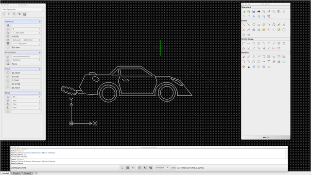
I used the eclipse tool to add the gas tank opening and the elliptical freehand (cloud form) to depict the exhaust fumes.
Parametric 2D
For the 2D parametric design I applied it to the exhaust fumes on the far left of the sketch. In order to do that:
- Step 1:
Selected the fumes sketch and chose the "pattern" tool
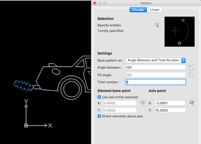
- Step 2:
Specified the number of duplicates and at which angle. Once checked, I pressed ok and got the wanted result
3D Software Trials
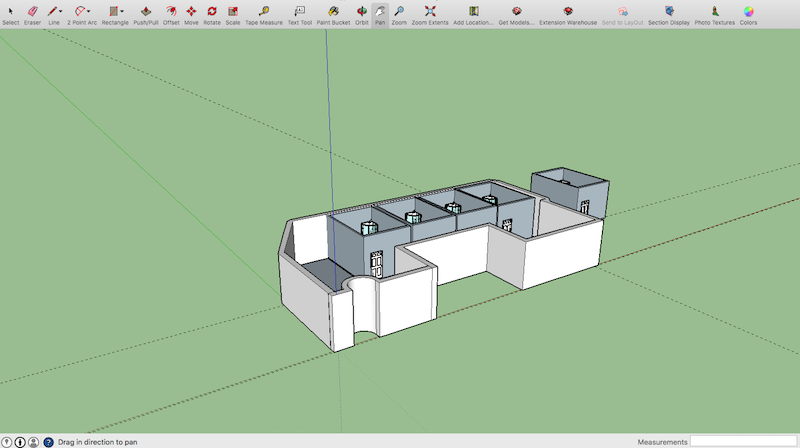
- SketchUp
- I mainly used the lines, arc, rectangle commands, and used the push/pull tool to make the parts/objects 3D
- SolidWorks
DOWNLOADS
TheBox.f3d
Hinges.f3d
Grips.f3d
Bracket.f3d
Car.dwg