
Electronics Production
COUNTDOWN
For this week we had 2 assignments:
- Group Assignment
- Make an in-circuit programmer by milling the PCB
- Tracing the PCB's cuircuits using CNC
- Cutting out the PCB to size using CNC
- Soldering components onto PCB
- Programming the PCB
Testing the CNC Machine
So the idea was to understand the different settings of the CNC milling process that could affect the output products.
There are many variables in the Milling process setting that could be changed and respectively affect the output of the machine.
The settings are:
- RPM of Milling Bit is the variable that controls the rotating speed of the milling bit.
- Mrilling Bit Diameter is the variable that is directy related to the bit diameter. The bigger the diameter, the less we can achieve thin connecting lines.
- Feed Rate is the variable that controls the rate the milling bit moves on the surface of the copper board. Milling the inner lines requires a normal feed rate. However, milling the outer parameter of the pcb required very slow feed rate.
- Offset Number is the variable that controls the number of passes the milling bit does over the same path. This setting majorely affects the final product. Paths that are not cut in the first pass post probably will be cut during the other passes.
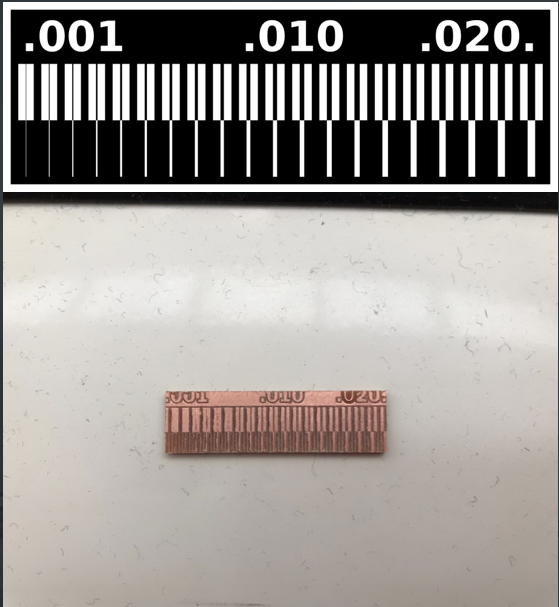
Saying that, we started by a Test File we got from the internet, that has different paths of vairious thicknesses. We tested milling this image using the milling bit of diameter 0.2mm.
The test file was downloaded from the following Link
After that, we noticed that not all paths stayed, and the thin paths (less than 0.005mm) were missing. Thus we deduced that our limitation is that the milling bit cannot mill paths less than 0.005 mm.
Individual Assignment
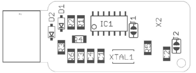
The group assignment is characterizing the CNC milling machine we used in the lab to produce PCBs, specifically the fabISP provided by our FabAcademy instructor. We received two files in PNG format:
- Interior traces
- Outer traces (Cut)
Both pictures had to be modified on FabModules to generate the G-code to send to the CNC machine.
On Fab modules, certain steps need to be taken to generate the proper G-code:
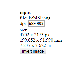
- Choose input format and select image (png) that the g-code is going to be generated from
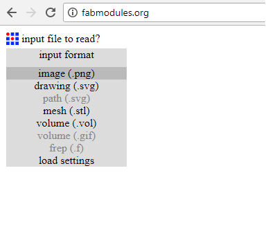
- Then select the file from the specific folder

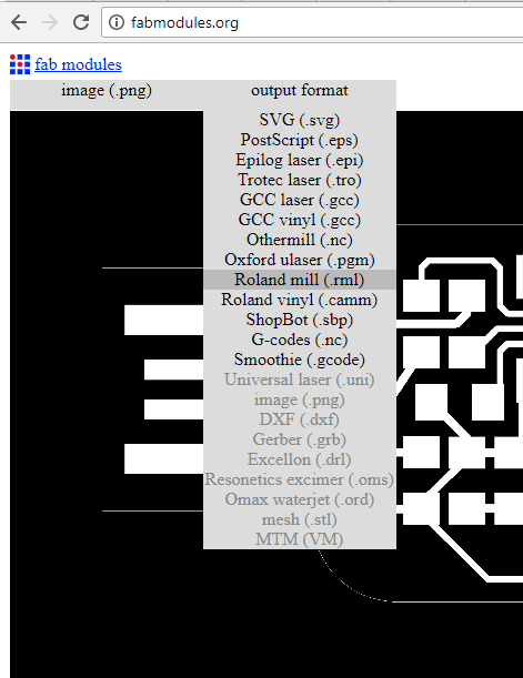
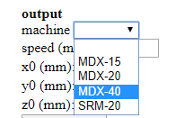
- Then go on to Output format and select the format that applies to the CNC machine you are using, in our case it was Roland mill (.rml)
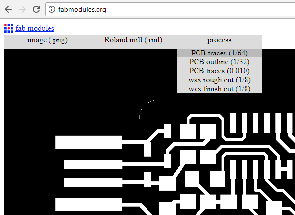
- Then select Process and choose PCB traces (1/64)
- Under Input, make sure you have the correct DPI, it should be (599.999), Do not adjust anything else In our case it was different since one of the components wasnt available, we had to adjust the original file to add it and ended up with a DPI of 1500
- Then under Output, select the CNC machine you are using, it was a Roland MDX-40 in our case and do not adjust anything else, the only thing you should do is double check that the speed is 4 mm/s for tracing the interior of the board
- Then Under Process, adjust the cut depth which should be 0.0 mm for the internal tracing, the tool diameter (drilling bit) which was 0.1 mm in our case
Number of offsets is 4
Offset overlap is 70%
No other adjustments should be made.
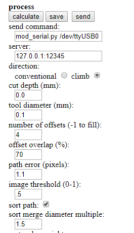
- Once the Input, Output, and Process tabs are double have been adjusted and double checked. Go ahead and press the calculate button
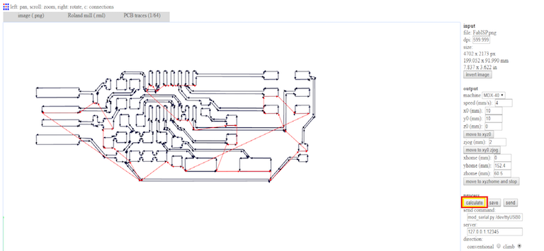
- Then finally click the save button next to the calculate button and save it to the designated folder. It would be saved as an .rml file
NOTE: While on FabModules, set X and Y to 0 if you are looking to be economical while tracing the boards (The carving point would be much closer to the starting point).
Milling (printing) PCB's interior traces
In order to start this, the following steps need to be taken:
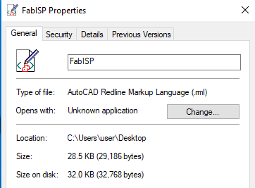
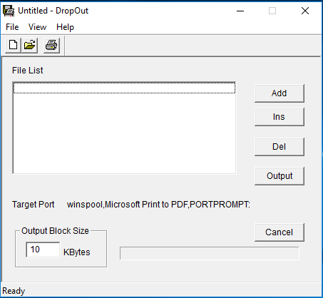
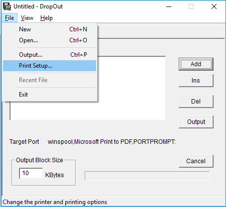
- First off you need to use the application Drop-Out to send the .rml file we you just made to the CNC machine
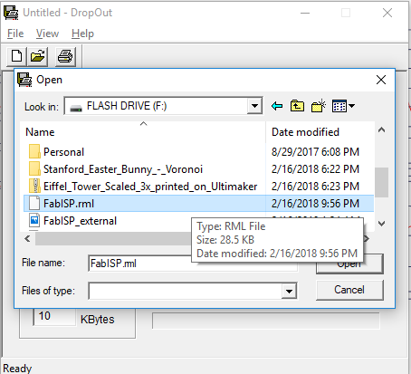
- On the Drop-Out application press the add button and choose the .rml file you created and press open
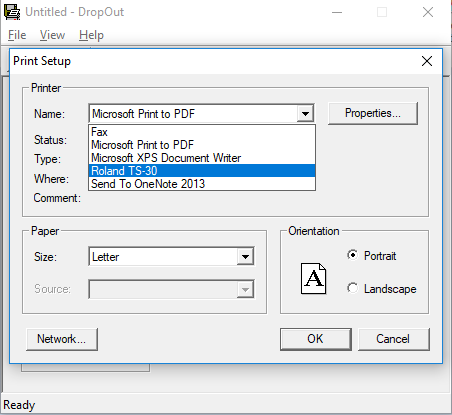
- Then go to File and select Print Setup
- On the Print setup first choose the name of your printer, in our case it was the Roland TS-30
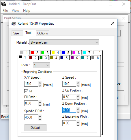
- Then go the Properties and press the Tool tab, the only thing that should be adjusted are the Z down position and Z engraving pitch both should be at 0.00 mm
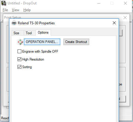
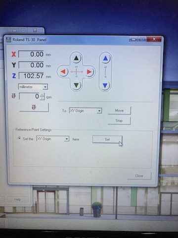
- Then go on to the Options tab and select Operation Panel
- Set the X and Y-axis on where you want you PCB to be engraved on the copper board inside the CNC, press the XY axis SET button
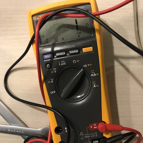
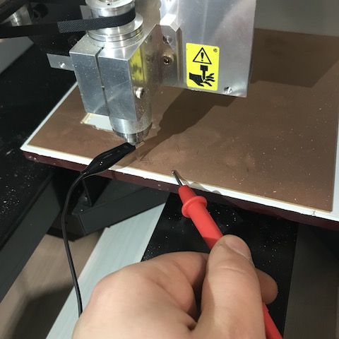
- As for the Z-axis, newer CNC's have an automatic sensor that sets it, in our case on the MDX-40 we have to do it manually. In order to do this delicate process we need to gradually bring it down onto the board, have a multimeter with the beep mode on and have one of the cables on the copper board and the other on the drilling bit. In that case as soon as the drill-bit touches the copper board the multimeter would beep. Make sure to go extremely slow at the end so you dont risk breaking your drill-bit
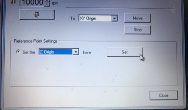
- Once you hear the beep, you know that the drilling bit is right at the surface and you can go back to the operational panel (on Drop-out), select the Z-axis from the dropdown menu and set the Z-axis.
- Once everything is set press OK until you reach the first page of drop-out and press theOutputbutton. Your CNC machine should now start the process of milling/engraving the copper plate set inside. watch the process until its done
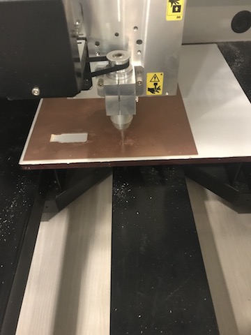
- Check the final result, using a multimeter with the beep setting to make sure components are isolated and all conductivity channels are connected
Milling (printing) PCB's Outer Cut
In order to proceed with this, the following steps are taken:
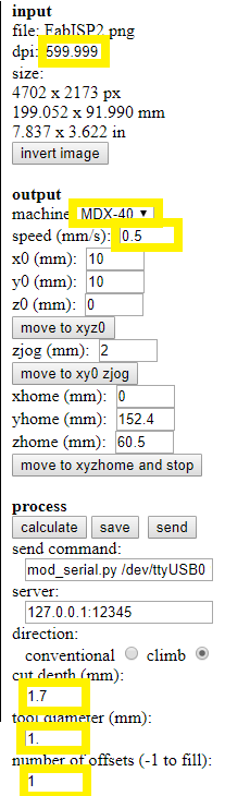
- First to you need to prepare the .rml file for the outer cut of the PCB by following the exact same steps as the ones for the interior. Only this time make the necessary adjustments shown in the image below.
(check the DPI, select Machine, Speed is 0.5 mm/s for cutting, the depth of your copper board ours is 1.7mm, select the tool diameter 1.00 mm and change the number of offsets to 1. )
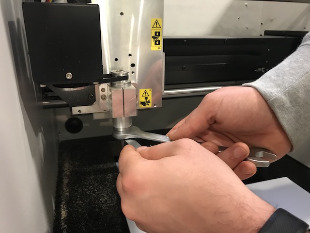
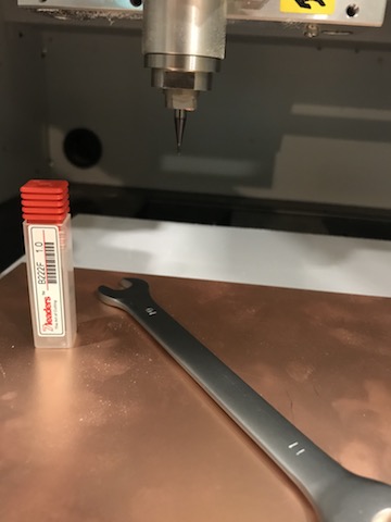
- Then change the drill-bit into the one for cutting through the copper plate, we used the 1.00 mm for that process. In the case of the Roland MDX-40 we have to use the wrenches to change the drill-bits
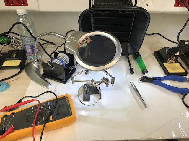
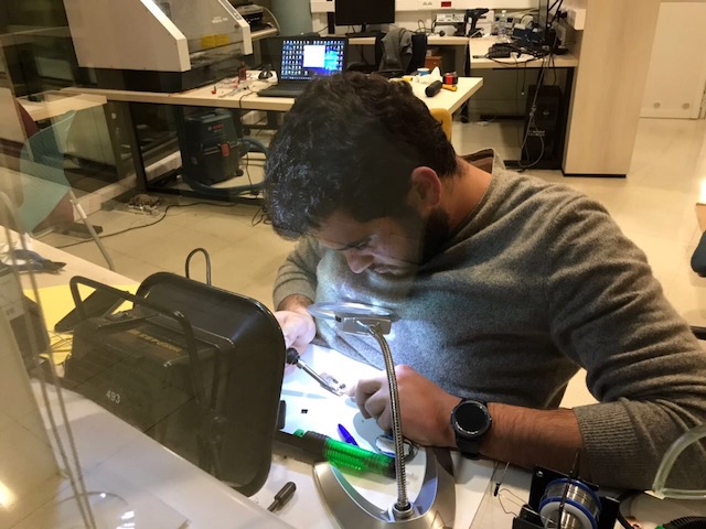
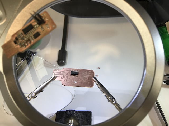
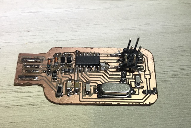
Soldering
Now that we have the PCB layout cut-out, we move on to soldering. In order to do so we first need certain tools to proceed, find the list with specs below:
- Soldering Iron: set at 320 degrees celcius
- Solder wire: 0.5 mm
- Tweezers
- Desoldering copper
- Vacuum
Use a fine tip for the soldering Iron as the components are small, and a magnifying glass would be more than just helpful.
Then follows the list of components:
- Atiny44A Microchip
- 2 x 3.3V Zener Diodes
- 1 x 0 Ohm Resistor
- 1 x 499 Ohm Resistor
- 1 x 1 KOhm Resistor
- 1 x 10 KOhm Resistor
- 2 x 49.9 Ohm Resistor
- 1 x 20 MHz Crystal
- 1 x 0.1 uF Capacitor
- 2 x 22pF Capacitor
Now for the actual soldering, I used the schematic provided by our remote instructor. (We actually had to go through Eagle and adjust the actual one because we couldnt get our hands on some components and had to improvise).
Then set-up your soldering station and start the process.
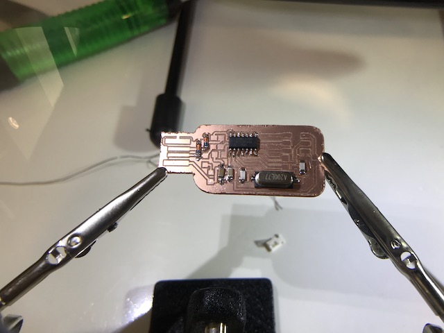
Now for the final step in this process, make sure all connections are ok using the multimeter on the beep option. And you should be set to move on to the next step.
Programing the PCB
So again in order to do so certain steps need to be taken, and the are as follows:
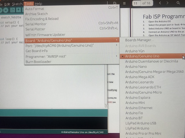
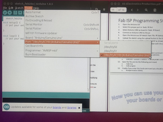
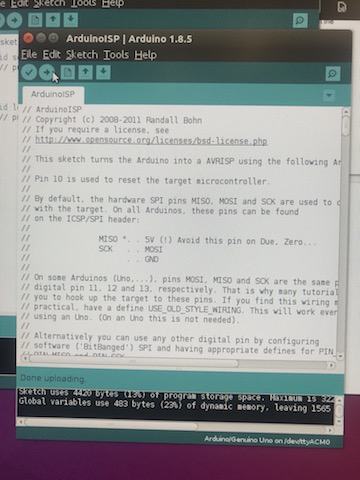
- First we need to cennect the Arduino to the PC, open the Arduino IDE and make sure you have the right board and port under the tools tab

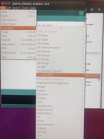
- Then under file and examples, you need to find the ISP program and upload it to the Arduino
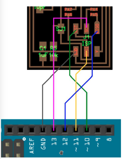
- Now disconnect the arduino form the PC and connect it to your ISP using the following schematic
- Once the connection between the arduino and your ISP is made, connect the arduino to the PC again. And run the terminal (on LINUX) and type the following commands
- sudo apt-get install flex byacc bison gcc libusb-dev avrdude
- sudo apt-get install gcc-avr
- sudo apt-get install avr-libc
- sudo apt-get install libc6-dev
- Press enter after each command and type 'y' if prompted
- Then you need to go to the Desktop directory through the terminal and download a zipped file and unzip it. using the following commands
- cd ~/Desktop
- wget http://academy.cba.mit.edu/classes/embedded_programming/firmware.zip
- unzip firmware.zip
- After you unzip the file, through the terminal enter the unzipped file named 'fabISP_mac.0.8.2_firmware/'
- Then add the following commands on the file's directory
- make clean
- make hex
- nano makefile
- Here you have to look for the AVRDUDE and add a hastag next to the last one so it goes as a comment
- And skip a line under it and add 'AVRDUDE = avrdude -c stk500v1 -P /dev/ttyACM0 -b19200 -p $(DEVICE)'

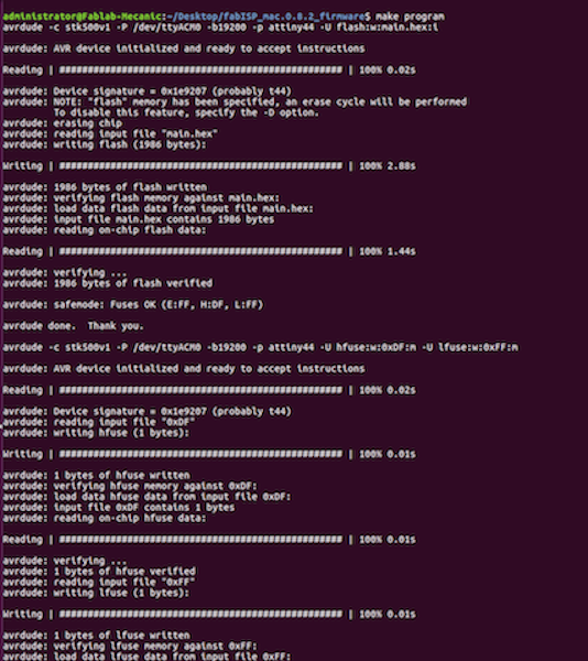
- make fuse
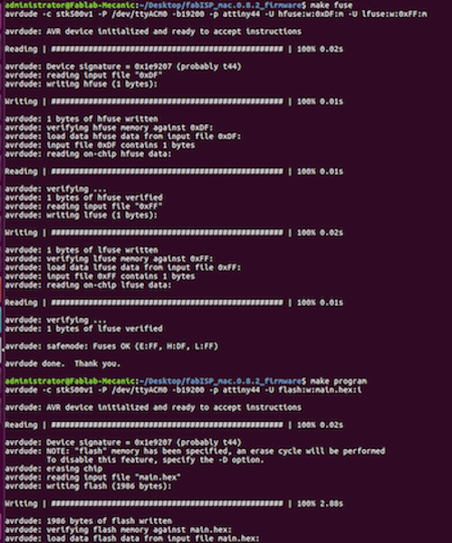
- make program
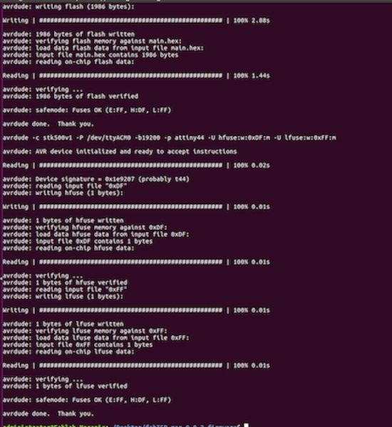
- Finally, disconnect your ISP from the Arduino, Unsloder the Jumpers and plug it into the PC
- Then type in the terminal, 'lsusb'
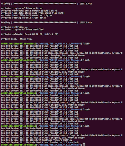
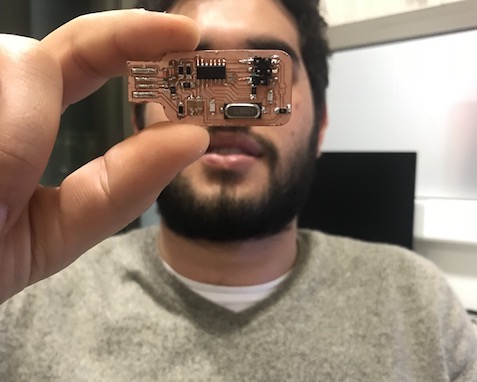
And you now have your own ISP!
Downloads
ISP External
ISP Internal
Firmware ZIP