So the objective of the fifth week is to discover the various 3d printers available in the fab lab and the different technologies used. There are many technologies nowadays that are considered to be under the umbrella of 3d printing, by other words additive manufacturing. Among those are:
FDM - Fused Desposition Molding
This technology is the most commercial technology available in the market. It mainly uses filaments (PLA, ABS, PVA, NYLON..) that are heated and extruded in layers to produce the final shape we need.
Stereolithography
This technology is resin based and it uses a light source to cue the material. It is mainly used for producing small part willhigh precision and quality, usually for the jewelary or dental applications. There are two different mechanisms used for this technology:
SLA, that uses a Laser Beam as a light source
DLP, that uses a Projector as a light source
Slective Laser Sintering (SLS)
This technology starts with powder matrial that are melted and binded together using a beam of laser. It is usualy used for building durable functional prototypes with high quality finishing.
Slective Laser Metal (SLM)
This technology starts with a metallic powder matrial that are melted and binded together using a beam of laser. It is usualy used for building metalic parts.
Inkjet - Material Jetting
This technology starts with building material of various colors to produce parts having a variety of colors at the same time.
We had a Group Assignment and an Individual Assignment this week.
Group Assignment
The group assginment was to test the design rules of the 3D printers available in the lab. To achieve that, we printed various test parts on the different printers we have in the lab to study the limitations of each and the quality we can achieve.
You can check the Group Assignment on the following link: Group Assignment
Machines Used
The main machines used in this week's assignment are the 3D Printers and the 3D Scanner.
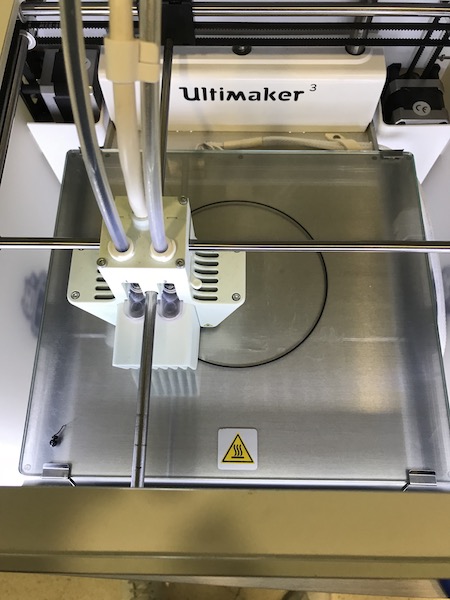
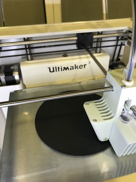
Ultimaker 3 is one of the FDM 3d printers. I was used for 3d printing small scale objects up to 20x20x30 cm.
DeltaWASP 4070 is one of the FDM 3d printers. It was used for 3d printing larger scale objects up to 40x40x70 cm.
Form 2 is our SLA 3d Printer. It was used for high-resolution prints.
Scan in a Box is the 3d Scanner available in our lab. It is used for scanning small objects.
Software Used
The following software were used for 2D Vector Design in this week's assignment:
Fusion 360 was used for 3d modelling in this assignment.
AutoCad was the main software used for 2D design. I used it to design in 2D and set the dimensions i want to use in the 3d model.
Cura was the main 3d printing software used in this assignment for FDM printers. I mainly slices any 3d object and generates the gcode that is supposed to run the 3d printer.
PreForm was the main 3d printing software used in this assignment for the Form 2. I mainly slices any 3d object and generates the gcode that is supposed to run the SLA 3d printer.
1- Characterizing our 3D Printers
In order to discover the limitations of the different 3d printers we have in our lab, and the various qualities we could achieve using it, we decided to make various tests. To undergo the tests, we needed test files that have various variables in one design, where we can check various limitations at the same time.
Preparing Files and 3d Printing
To start 3d printing, we need a digital 3d model of the object we need to print. The 3d printing software usually recieves a 3D model in .stl form as an input, to generate the g-code based on it.
To print anything on the 3d Printer, the follwing procedure has to be followed:
Building the Design
The design, which is a 3d model, can be produced on any 3d modelling software available in the market. This could be anything from Fusion 360, 3d Max, Rhino, 123D Design and many others. The common things between all software is that we have to export the design in .stl form once the design is ready. The .stl form is what the slicer software uses to produce the g-code for the 3d printer.
Slicing and Choosing the 3d printer's Settings
After the design is ready, the next step is to choose the settings we need to produce a 3d printed product having the best result.
There are different variables that affect the final product coming out of the 3d printer.
Among those variables are the following:
Layer Height which represents the thickness of each layer in the z-direction, and mainly affects the surface quality of the printed shape.
Wall Thickness which is supposed to be a multiple of the nozzle extruder
Infill Desity that controls the density how much the product is filled from the inside.
Infill Pattern which controls the pattern of the filling inside a body. Different patterns achieve different strengths.
Printing Temperature which controls the temperature of the nozzle extruding the printed material. Different material have different melting temperatures.
Build Plate Temperature which controls the temperature of the build plate. This option mainly helps the produced body to stay stuck on the build plate, and it help preserve the temperature inside the build platform thus leading to well adhesion between the layers extruded at each level.
Print Speed which controls the speed of printing. The slower the speed, the higher the quality we get.
Generate Support is the setting used to generate support for complicated parts that have unsuported parts at a certain level. Without supports, the extruded material will melt down and lead to a bad quality print. The density and pattern of the support could be also controled. In addtion to the, we can print support using different material than the material of the main body.
Build Plate Adhesion Type controls how the printed body adheres to the build plate. There are three main adhesion types, mainly skirt, brim and raft.
Forwarding the Job Order
After choosing all the variables, the g-code is produced using CURA the slicing software, which will be saved on a flash drive or a memory card. The flash drive will be inserted in the machine and printed directly on the 3d printer.
Identifying our 3D printers
In our FabLab we have 4 different 3d printers, find their detailed description below:
DeltaWasp 4070
Features & Performances
layer resolution: 0.05 > 0.25 mm
precision: X-Y 0.05 / Z 0.01 mm
print speed: 250 / 400 mm/s
move: 6.000 / 10.000 mm/s2
travel speed: 150 / 400 mm/s
print area: Ø 400 – h 670 mm
printing volume: 84 liters
TECH & MATERIALS
fff filament: Ø 1,75
materials: abs, pla, hips
experim.: pet, nyl, flx, pst, pur, lay
nozzle Ø: 0.4 / * 0.7 / * 0.9 mm
extruder: porcelain, ceramic, clay
FormTwo (Formlabs)
Specification
Dimensions 35 × 33 × 52 cm
13.5 × 13 × 20.5 in
Weight 13 kg
28.5 lbs
Operating Temperature Auto-heats to 35° C
Auto-heats to 95° F
Temperature Control Self-heating Resin Tank
Laser Specifications EN 60825-1:2007 certified
Class 1 Laser Product
405nm violet laser
250mW laser
Ultimaker 3
Dimensions: 215 x 215 x 200 mm
Layer resolution
0.25 mm nozzle: 150 - 60 micron
0.40 mm nozzle: 200 - 20 micron
0.80 mm nozzle: 600 - 20 micron
The Ultimaker 3 Extended has the exact specs of the regular one except that it has larger dimensions, the Z-Axis to be precise.
Dimesions: 215 x 215 x 300 mm
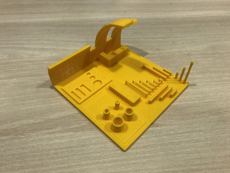
Test Files in Depth
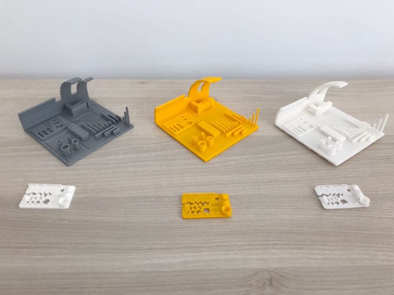
As stated earlier, the 6 tests were made on three different printers; The Ultimaker 3, DeltaWasp 4070, and the Form2 (Formlabs). The test files included various benchmarking qualities that would help us identify the various pros and cons of each printer. The tests in detailed inspection are found below:
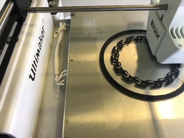
Ultimaker 3
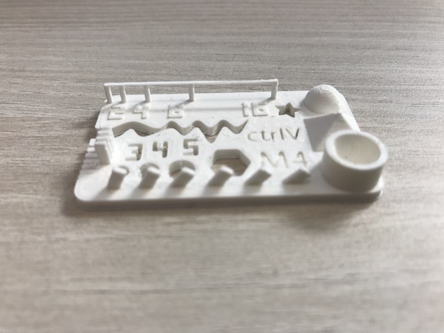
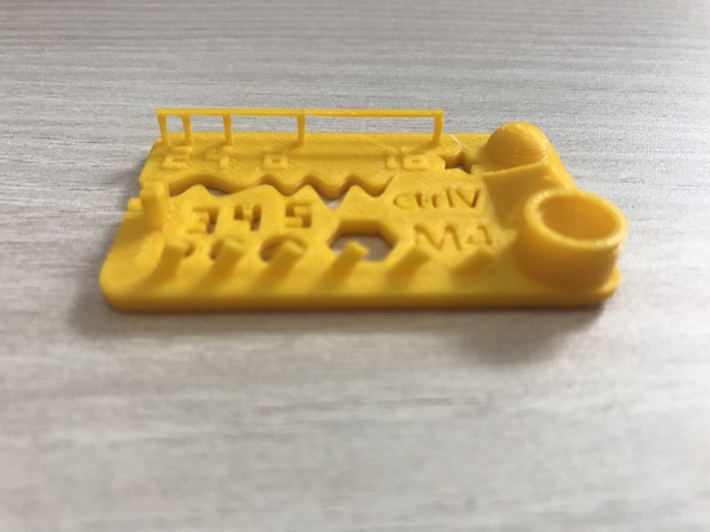
Small Test
All letters and finishings were acceptable with no remarkable misprints.
All the letters, numbers are clearly read and the geometrical shapes are well defined.
The angled collumns are also straight with no obvious issues.
The bridge was rigid even when it came to the longer distances without supports.
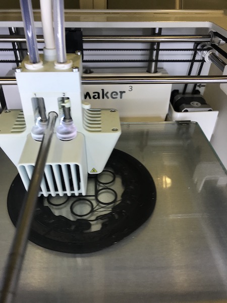
Large Test
All letters and finishings were acceptable with no remarkable misprints.
All the letters, numbers were not clearly read but the geometrical shapes are well defined.
The angled collumns were made perfectly, however we do notice some misprints when it goes over 50 degrees
The bridges were rigid even the longest ones
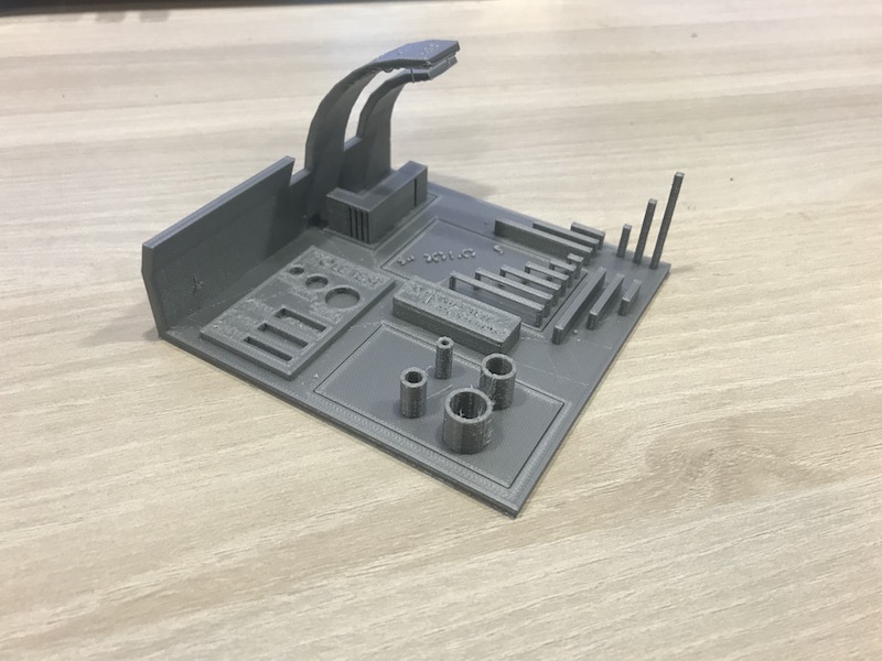
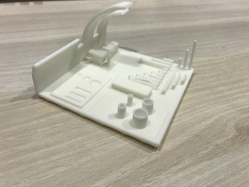
DeltaWasp 4070
Small Test
All letters and finishings were acceptable, with a note of the contouring layers around the letters being a bit 'empty' and not very well defined.
The letters are clearly read and the geometrical shapes are well defined.
The angled collumns are a bit more slanted as they go up the Z-axis (height), meaning they would need supports if they were to be a bit longer
The bridge was rigid even when it came to longer distances without supports
Large Test
Letters and numbers that were engraved are barely readable if not impossible in some cases.
The geometrical shapes are very well defined, except for the straight collums, once it reaches a certain height it started deforming
The slanted curves were fully drawn, yet again right when it crosses the 45 degree mark it starts misprinting the base layers
The bridges were very well defined and the rigidity is great
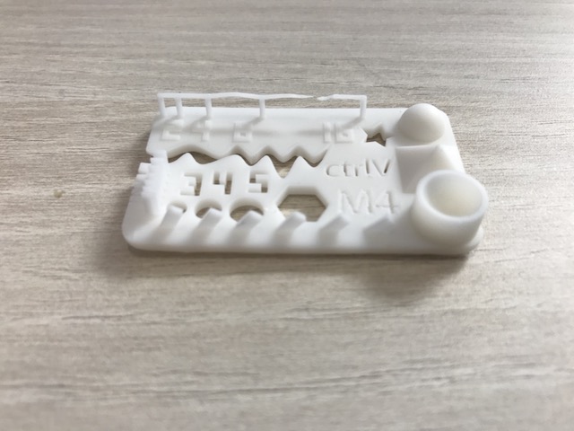
FormTwo (Formlabs)
Small Test
All letters and finishing are of great detailed finishing.
The letters are very clear and the geometrical shapes extremely well defined.
The angled collumns are perfectly straight
The bridges were the only downside to this print. The shorter one was still standing and is fairly rigid. However the longer ones with larger distances were extremely fragile and deformed. Could be because of the curing process as the formlabs requires that after
It could also be added that when it comes to engraving, the formlabs is not very accurate and the finishing not very well defined.
Large Test
The letters and finishing are extremely well defined and precise.
Most geometrical shapes were impecable except for the one under the slanted slopes, It might be because the Form2 uses laser that starts from top down, so it was not very accurate in relation to that area.
The angled collumns were also made perfectly and no deformation to be noticed even when it exceeds 80 degrees, which is way better than the other 3d printers we have.
The bridges were acceptable when they are short and supported, the long ones were severely deformed.
It would be good to note that adjusting the temperatures could have given us different results. Also changing the extruders to be more precise could have helped. Since the Test designs included many small engravatures, smaller than 0.4mm, the slicer/gcode could have ignored them or was not able to draw them properly
Individual Assignment
Describing what I learnt from 3d Printers
I thought 3d printing would be a straight forward task, and the most crucial part was the design of the object and the way I Lay it in the slicer and the paramaters that could be changed. I was obviously very wrong. There are a lot of aspects that need to be taken into consideration after the design. The main factors would be extruding temperature, Heated bedplate temperature and the speed of which the extruder would move. That is all to be considered and reviewed after choosing the apropriate material for the print.
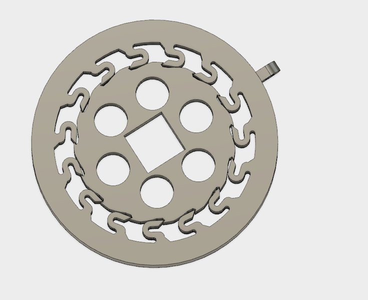
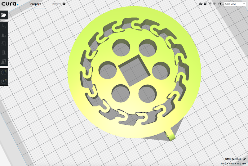
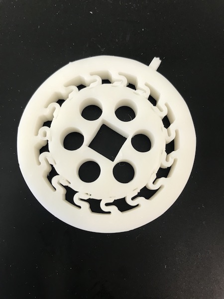
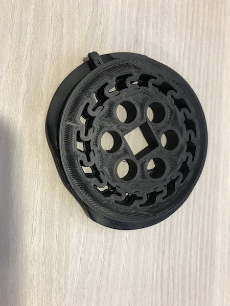
In my case I decided to do something that could be used in my final project. I decided to do the Ratchet gear, I have found some online and seemed possible, the only addition I had to insert were the springs to the sprokets would fold when going in the opposite direction (freespin). Then i started thinking of ways that would only require a 3d printer to make a ratchet gear. So I went ahead and designed the ratchet gear and assumably made the counter sprokets in a way that would bend a little and let the teeth through. I had to figure out which material needs to be used, PLA was my first option, then I wanted to see if I could get something a bit more flexible and found nylon but that was way to flexible and would not work with my design. After thorough research I ended up using ABS since it was more rigid and flexible at the same time. ABS is printed at much higher temperatures than PLA, and it really is my first time experimenting with 3d printers.
Since the design I had could have been done subtractively in two seperate parts, I did another design of car wheel cap that could not have been made. The design and printing process are found below.
The steps taken to design and print my ratchet gear are as follows:
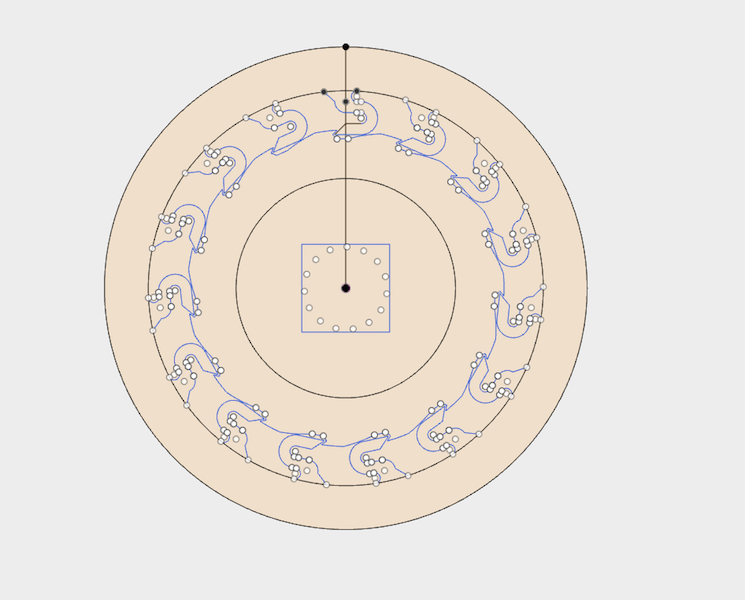
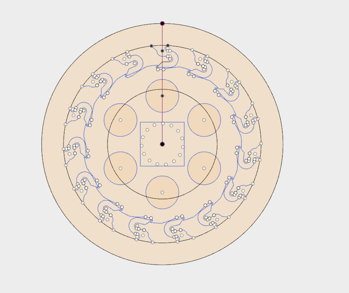
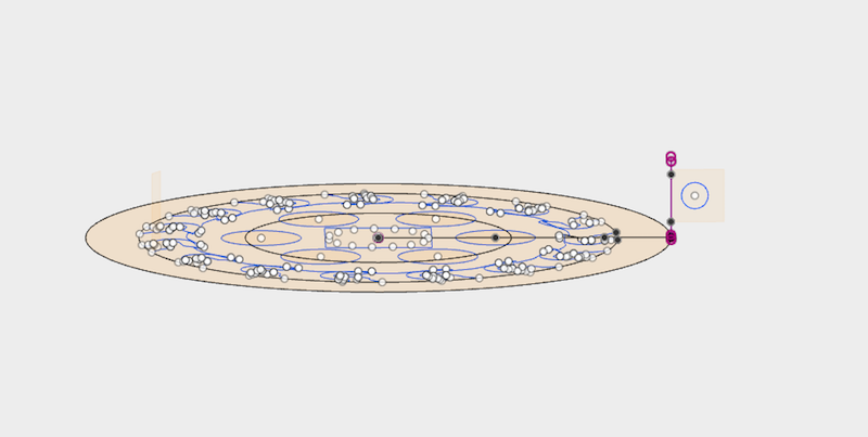
Designing the Rathchet Gear. I used Fusion360 to achieve this
I started the Sketch with 3 coinciding circles, whereas the center would be the central gear wtih the curved sprokets sticking out, second where the two sprokets would meet, and third where the flexible sprokets would come out from.
Next I added the flexible sprokets, I did one and used the circular pattern to multiply, 15 seemed the best scenario with the right spacing. I also added the slanted sprokets on the central gear using the center point arc and some lines
To refine the design I added a 2x2cm square in the middle for test purposes, so I could stick a tool in and rotate. Also added the circles around it since it was a stable surface and ABS would be rigid enough in the aim of saving material.
Then added a perpendicular hook that would then be used to attache a rope/chain onto the exterior walls of the ratchet gear that would eventually serve as a pulley of sorts.
Then went ahead and extruded the whole design to 15mm, I thought that would be a perfect size to actually test the ratchet gear, although I knew I could be risking the flexibility of the ABS on the outter sprokets.
Finally extracted the file in STL format to move it onto the slicer program
My design could not have been made subtractively because of the horizontal hinge on the edge. And a hole in it. This is for additional designs I'm gonna add later since this is related to my final project.
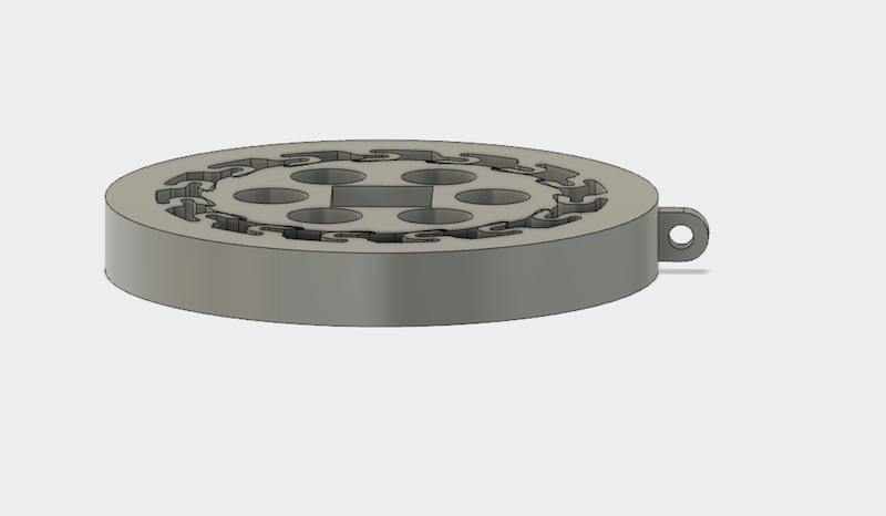
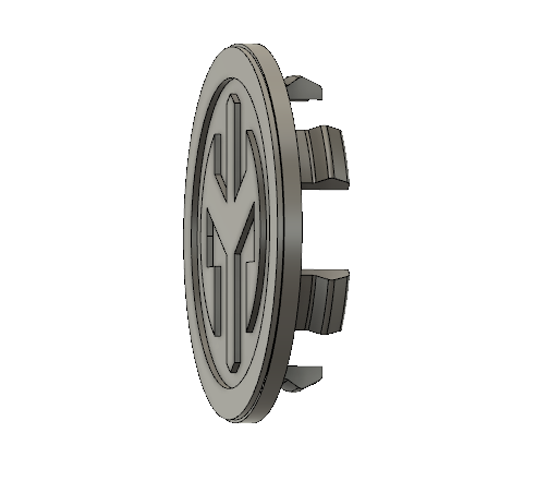
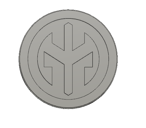
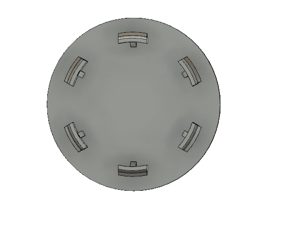
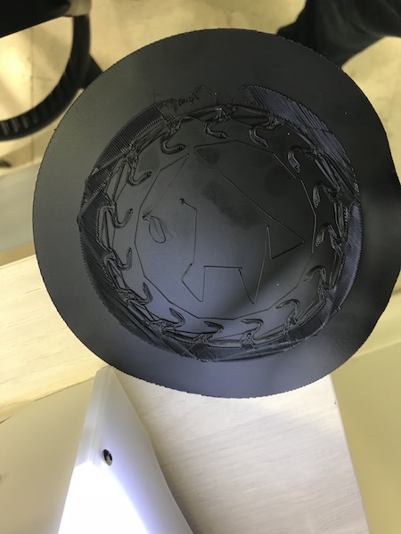
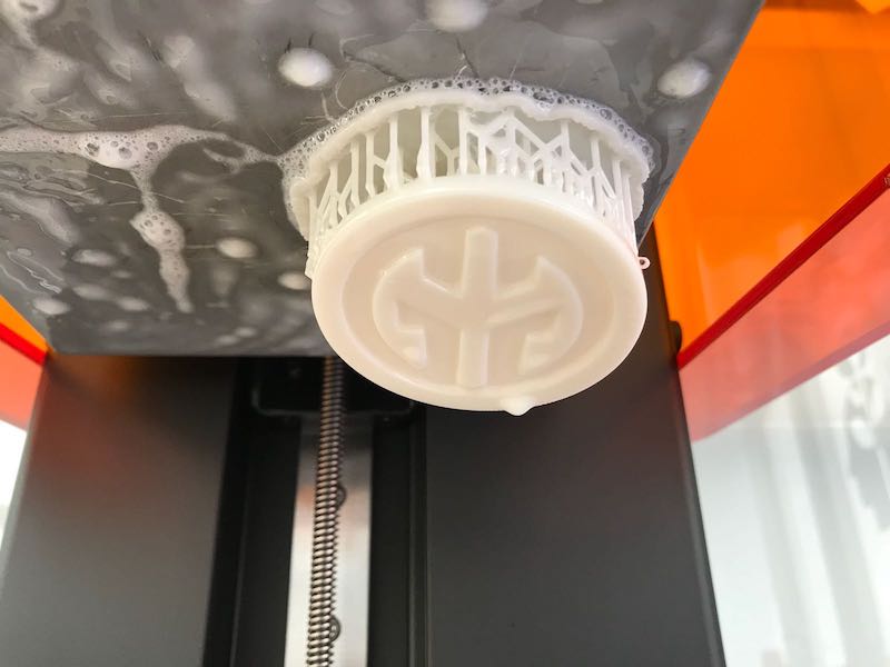
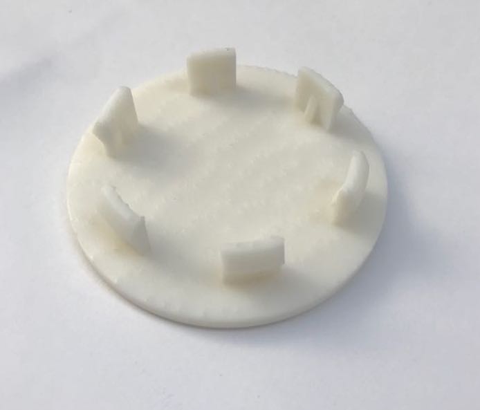
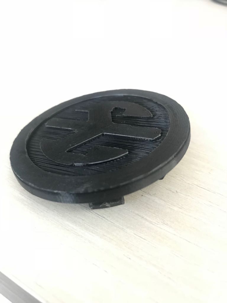
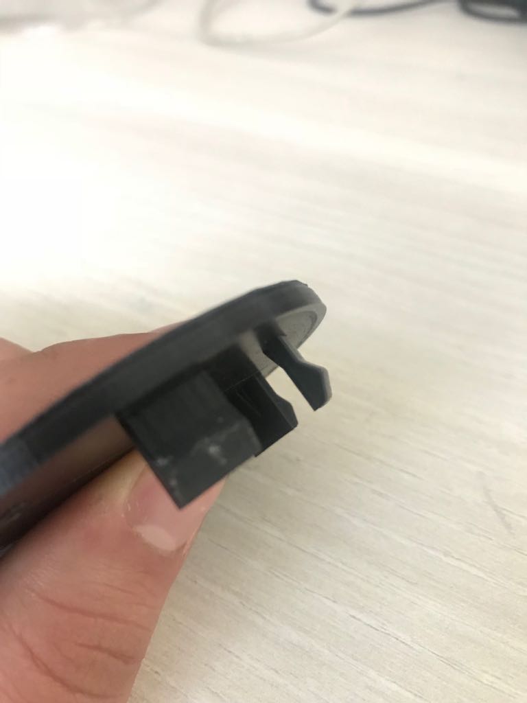
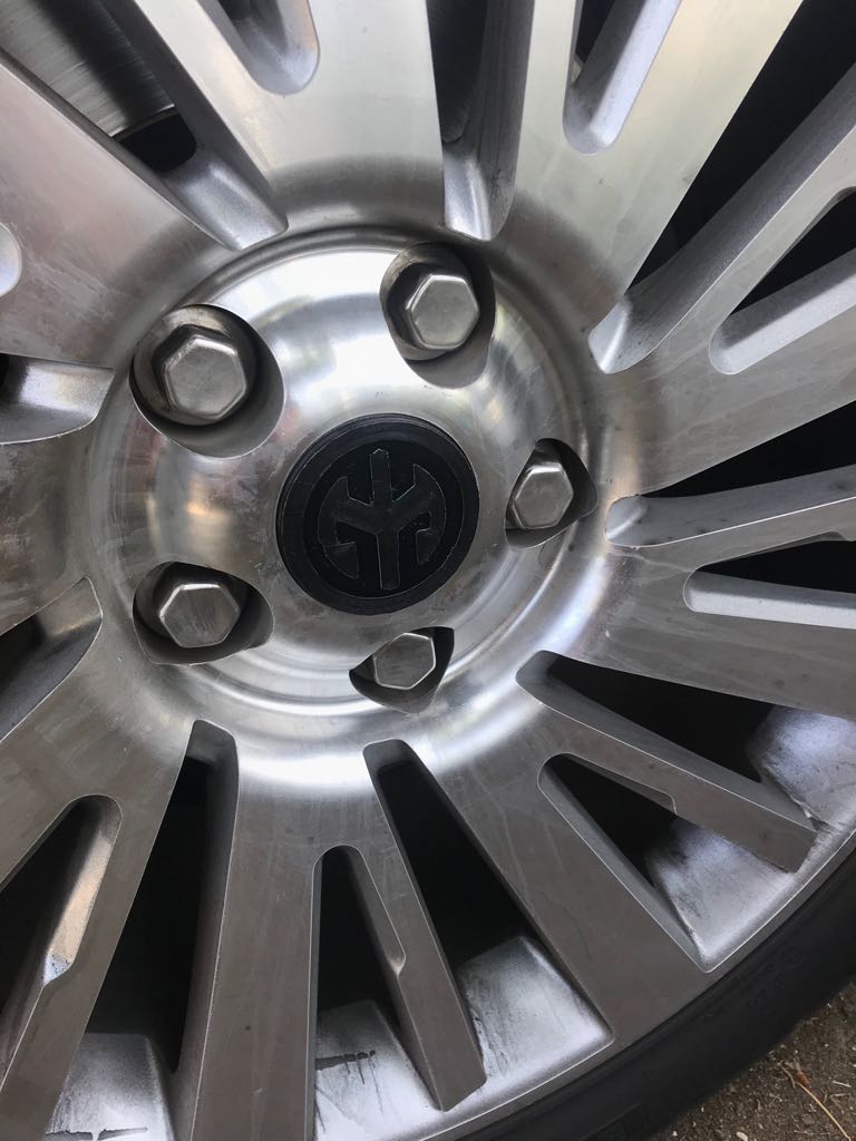
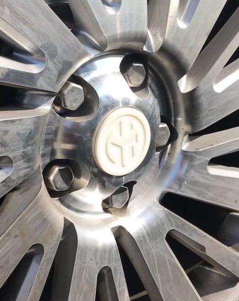
Wheel Cap design
To design the wheel cap I first took the dimensions of an existing one then proceeded with the design with a few simple steps
First I made a circle with and extruded it to the needed width.
Then started working from the inside area of the center wheel cap where teeth would be added to hold it on to the wheel itself.
Lastly using the circular pattern under sketch I made six of these teeth as the original one.
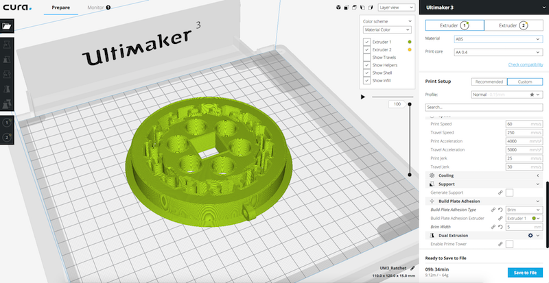
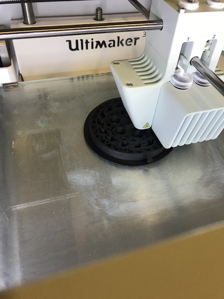
Slicing Program used was Cura, the Ultimaker's slicing software
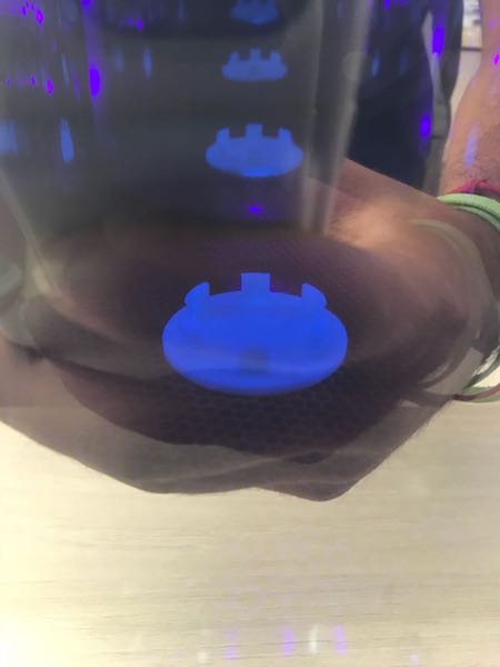
On Cura I first placed my object and chose the way it would be layed on the 3d printer's bed. Set the material I was using (ABS) which automatically adjusts most temperatures and then chose the Support structure I was looking for, since the object was relatively flat I had to only choose the build plate adhesion type, I actually used all of them because the printer kept on making mistakes and I was troubleshooting. I had to adjust the heated bed temperature to around 100 degrees and the extrusion speed to 30 mm/s after many tries
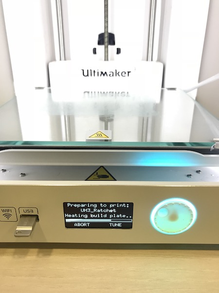
After saving the file on the external storage device (USB) I went ahead and plugged it into the Ultimaker 3.
Waited for the bed and extruder to heat to proceed with the printing
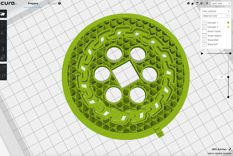
Once they were heated, the print started with the exterior brim
After the Brim was done it started doing the internal parts of the ratchet gear
That previous print quickly turned into a mess, after adjusting the temperatures and speeds and still not getting a proper result I went on and redesigned it to have a raft instead of the brim, increased the temperature and drastically redused the print speed
And again after waiting for hours to have the raft done, which looked great, once it got to printing the actual design it quickly went south
I figured after so many tries that there must be something wrong, after I revised my design and we calibrated the Ultimaker, I decided to scale down my design as I felt there was just too much wasted material for a trial. This last one also got tilted around the brim but the object was fine so I kept it going
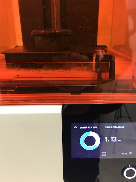
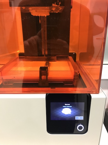
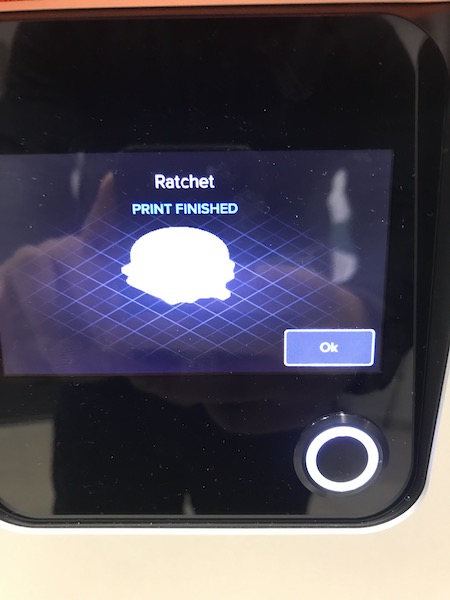
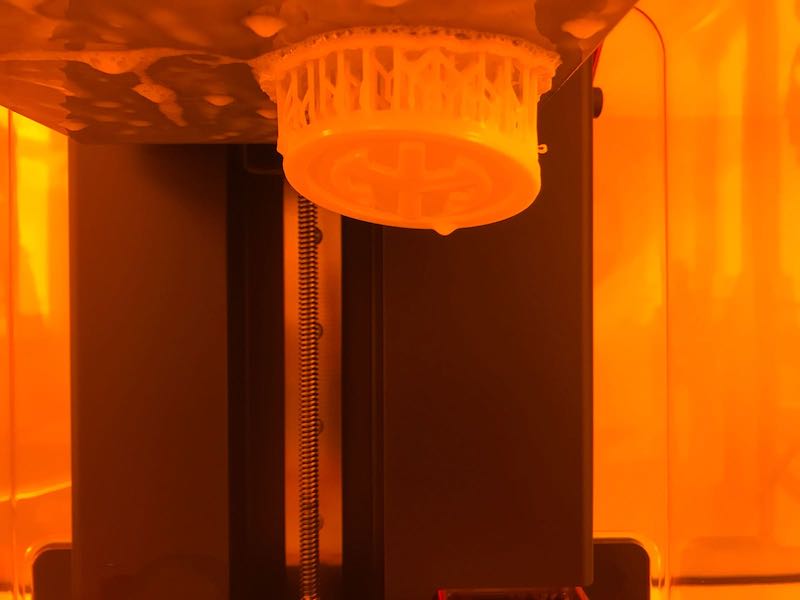
Form2 Print
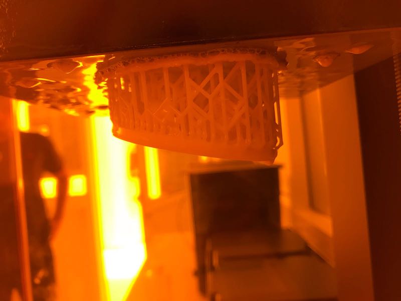
I decided to give the Form2 a try and added my file to the form slicer. This process is pretty straight forward. You just add the STL file to the slicer and it generates the supports, I might add it is also much faster to print
Waited a bit under 2 hours and the print was finished
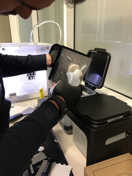
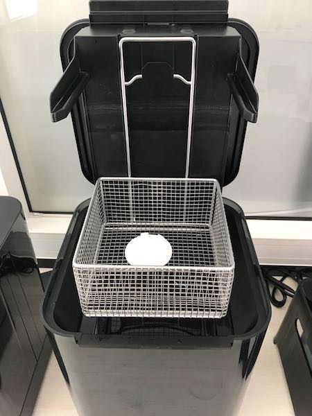
Then went ahead with the curing process where you have to remove all extra resin with alcohol and let it sit in a sink filled with alcohol for about 30min
Curing
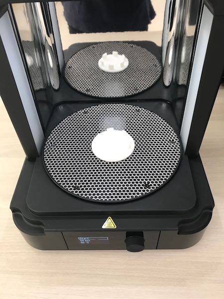
The final result was great, the details were very well defined, except that the parts werent movable, they were too close and stuck together, should have printed them seperately
3D print follow up
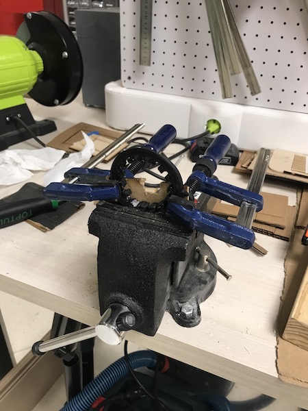
My 3D print with the ABS didnt go as planned, The gears were locked together, and even the sprokets. So technically as a 3D print it was not effective, it did not work. Since it is related to my final project, I will keep on enhancing the design and update on this page.
In the mean time I did what I do best, make it work no matter what it took. So I:
Broke them apart.
They were still too tight to rotate in any direction.
Sanded down the interior gear by hand and on the bench grinder.
Greased both interior and exterior gears using WD40.
Held it down with a 3 clamps and a piece of scrap MDF to hold it in place.
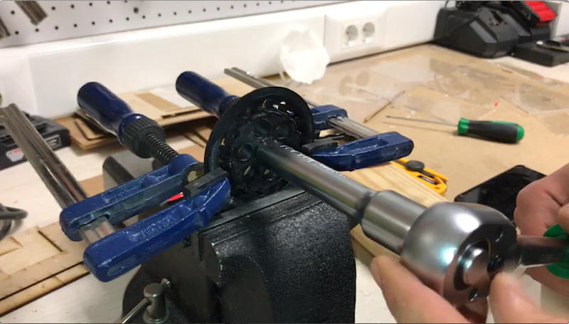
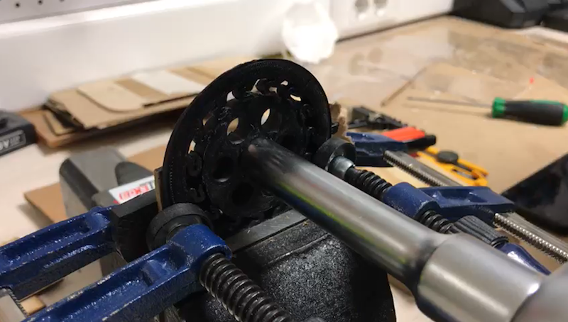
Once I had the outer gear held in place, I used a ratchet tool to go into the square I made in my inner ratchet gear. (ironic)
And this was the final result, it worked!
Needs many adjustments, but atleast I know what I need to do now and will keep this page updated.
3D Scanning
For my scanning assignment I decided to scan a press fitted chair, that didn't go too well as the design was complex and the chair itself had many openings which made it harder to put back together. But atleast I grasped the concept of 3D scanning and how to use the software to put the images together. So I decided to scan an object that I knew very well and what better than my hand.
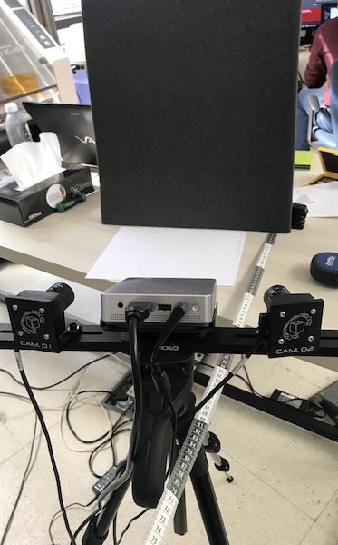
To start scanning, we first set up the projector and cameras 56cm away from the object that was set on a table with a dark background so it would minimize distortion in the scans taken.
Then using IDEA software, we connected the camera to our PC and were ready to start scanning.
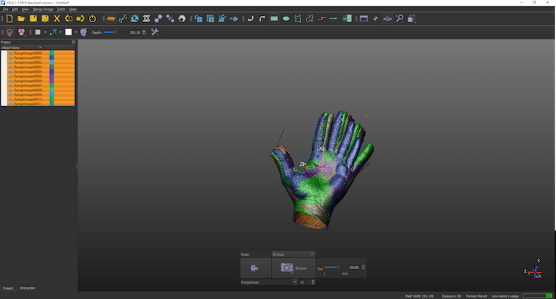
Proceeding with the 3D scanning I hold a specific gesture with my hand, which was an open hand because I have to maintain it and rotate it at different angles in the same position.
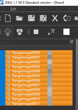
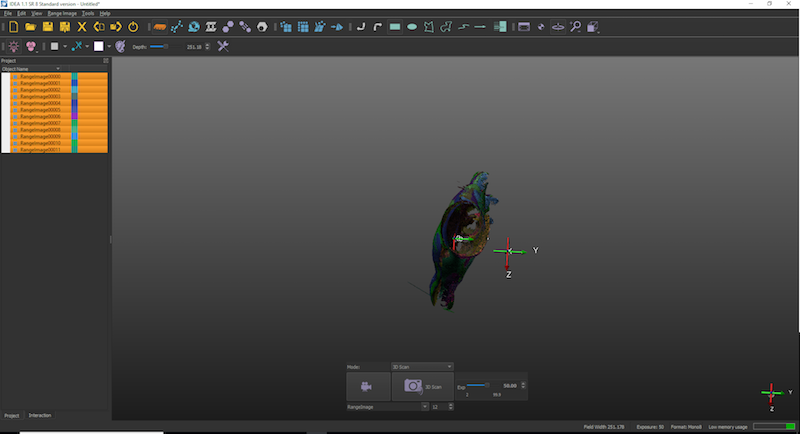
I took 11 photos (which I assume is relatively low) having more scans taken would definitely improve the final design, yet it also becomes more complicated to put them together
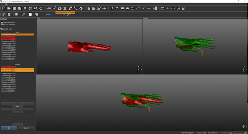
Putting the scans together, the ease of this highly depends on the quality of the scan initially taken, you get the different scans and have to manually put atleast 3 points of reference that would then align, having better scans would make you recognize the shapes and align them much more efficiently
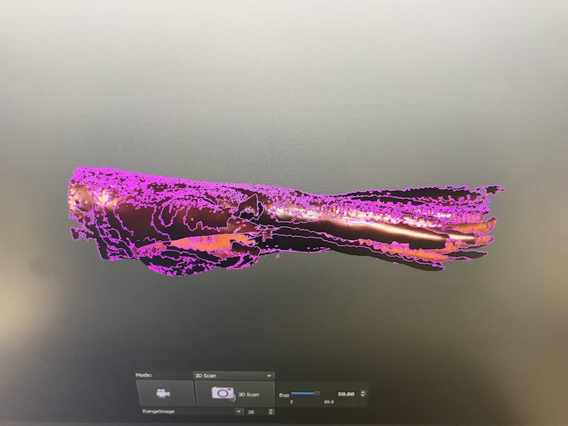
After choosing 3 points of reference on each scan, manually aligning them. This was the result
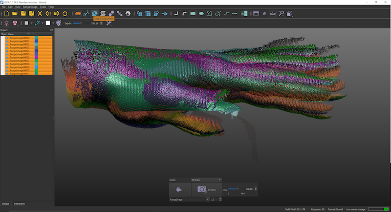
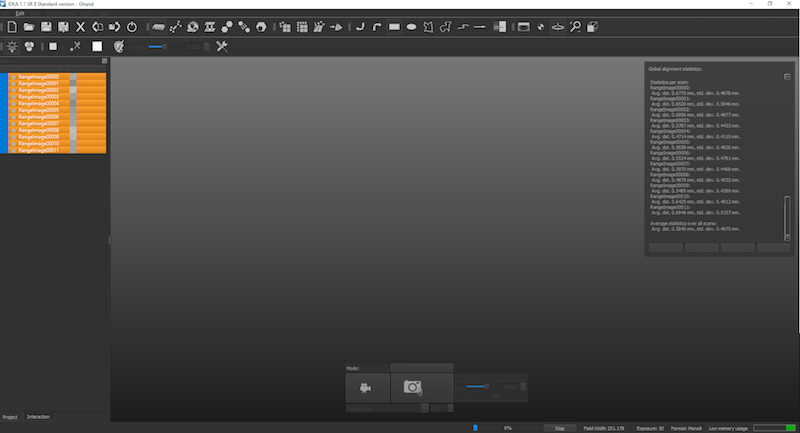
The result wasn't that great, so I started dabbling with the tools trying to see the extent of the software and how I could fix it other than repeating the whole process. And turns out there is a global alignment which does it automatically for you, but I think this only enhances the manual alignment done before. The result was a lot better.
This is the global alignment process shown on the left.
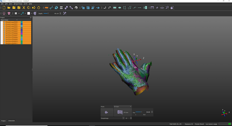
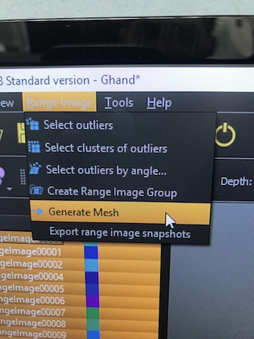
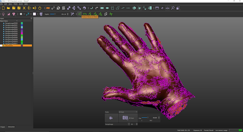
The design was slightly better aligned. After that I went on and generated a mesh which wraps the final alignment.
For the last step after generating the mesh, I used the reduce mesh noise tool and that was the final result.