Individual, Design, Produce, and Program a PCB while having at least 1 input and 1 output (Redesigning the Hello Board).
Group, Use the equipment we have at our Lab to observe the operation of a microcontroller circuit board.
Group Assignment
For the group assignment we had to measure our PCB's using an Oscilloscope to read the signal transfer from the PC to the PCB and signals within the PCB.
Bootloader
Video linked below under Final.
Individual Assignment
For the Individual Assignment we had to re-design the Hello Board, produce and program it. The following steps were taken to achieve the given task:
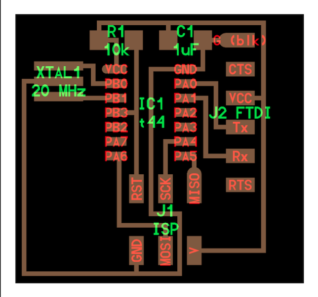
First I took a look at the Hello Board circuit and its components so I can have a benchmark to start.
The next step is designing the PCB, I used EAGLE software to complete this task
In EAGLE I had to download the FABACADEMY components to the PC and import them to the EAGLE Library. In order to use these components on my PCB.
The next step would be starting a new project on Eagle. And take the follwing steps:
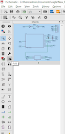
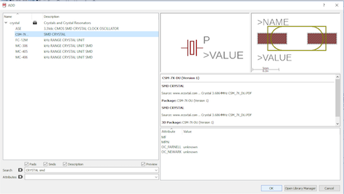
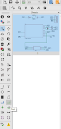
First you have to insert all the components that are going to be on the PCB. To add the components, simply press the ADD button in the tool bar (shown below), select and add the components (Crystal SMD in shown example)
The Components I used for this schematic are:
Attiny 44 Microprocessor
20 Mhz Crystal SMD
10k Ohm Resistor
499 Ohm Resistor
1uF Capacitor
2 x 22pF Capacitors
Digital Button
Red LED
10 x PinHeaders
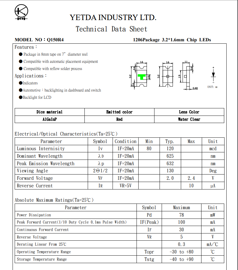
I found out the needed resistor for my LED by retreiving it's Datasheet from the web. Datasheets are available for all electronic components. And in this case had to do the equation to find R, the result was 100 Ohm, but since the smallest SMD resistor in the lab was 499 Ohm I had to use it.
Calculation:
R = Vr / Id
Vr = Vcc - Vdc
Vr = 5 - 2
Vr = 3
Id = 0.03 (30mA)
R = 3 / 0.03
R = 100
Once all components are added, use the net tool to draw out a trace out of the pins of each component using the NET button in the tool bar.
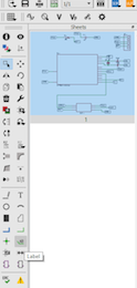
Now that all components have lines coming out, it is time to connect them in the correct order. Eagle has a way to simplify this process by adding labels on the end of each line and tagging it where to go. In order to do that press the LABEL button in the toolbar and assign each line accordingly (Main circuit based on the HELLO BOARD shown above)
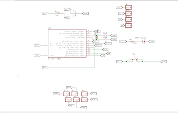
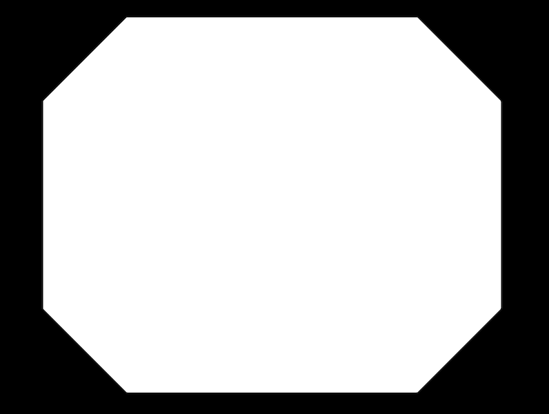
Once all the connections have been made, the Finalized board schematic looks like this. Then press the switch schematic button (shown below).
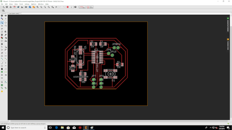
After switching to Board schematic, place all components in the right place. Use size 12 for traces and make sure no traces are over lapping. Once done the board should look like this:
Note: After selecting the move tool, select the crosshair in the middle of the component to move it.
After Finalizing the board, it is time to start the milling process. In order to do so the following steps need to be taken:
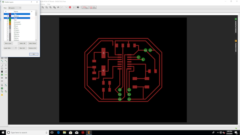
First you need to Export the Board from Eagle in PNG format, but in order to do so, you first need to clear your layers and only keep the base for components and traces.
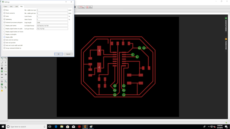
Then Change the display settings.
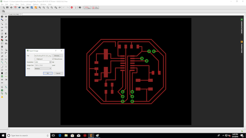
You can now Export the Eagle board file in PNG format.
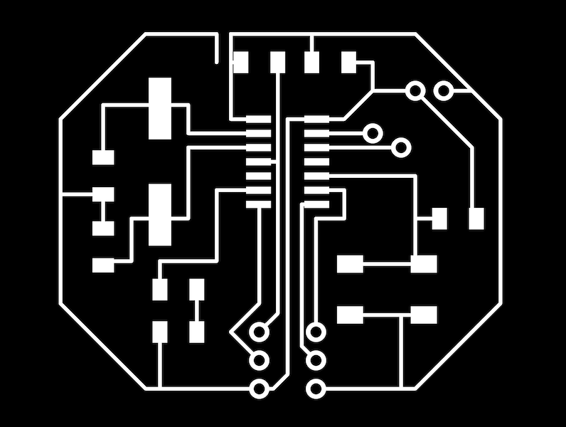
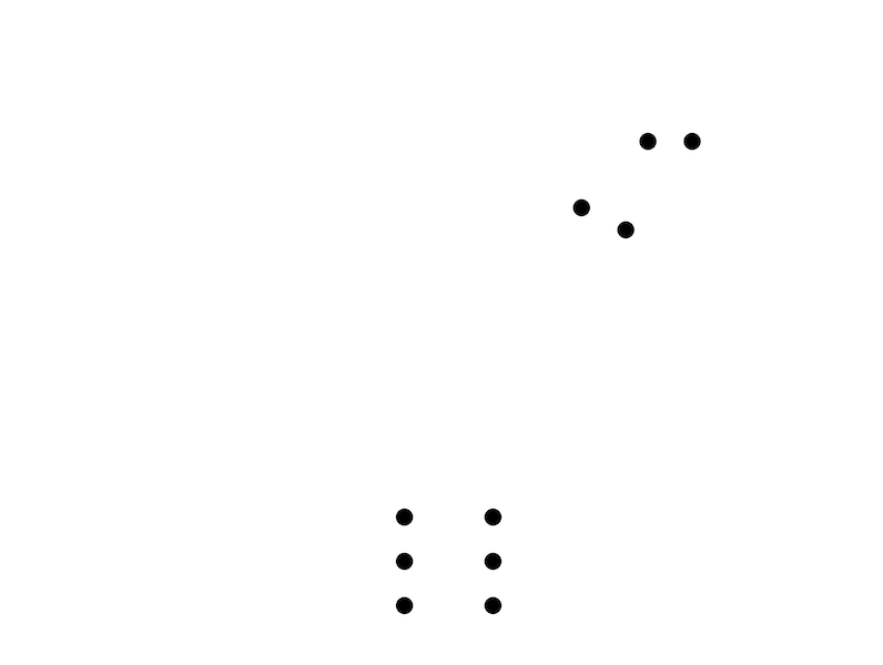
Open GIMP and open the exported Eagle file in PNG format. Change it to Monochrome (black/white) Fill the external layer to have the internal traces only, then Fill the interior to have the exterior traces. These files would then be used to generate the G-code for the CNC mill on FabModules (refer to week4 for more details). An additional picture was exclusively generated to be able to drill the holes for the Pin Headers. The the Images extracted to go on FabModules should look like the following:
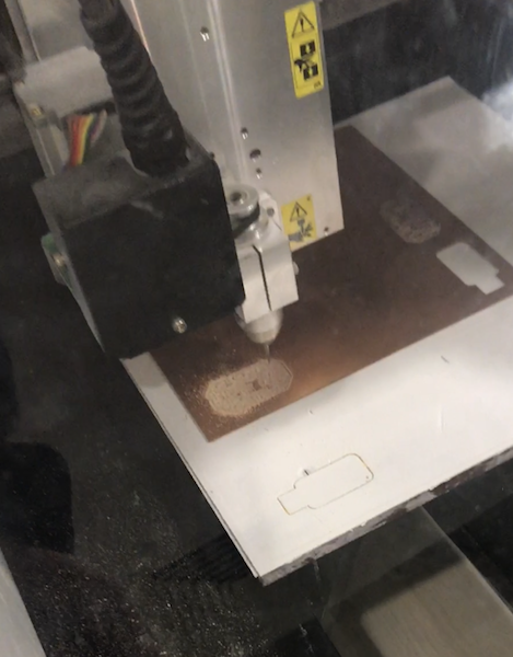
After having the RML files from FabModules, Start the milling process with the Internal traces, the PinHeader holes and finish with the exterior trace.
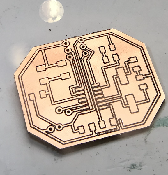
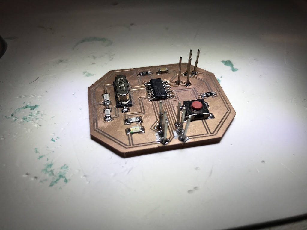
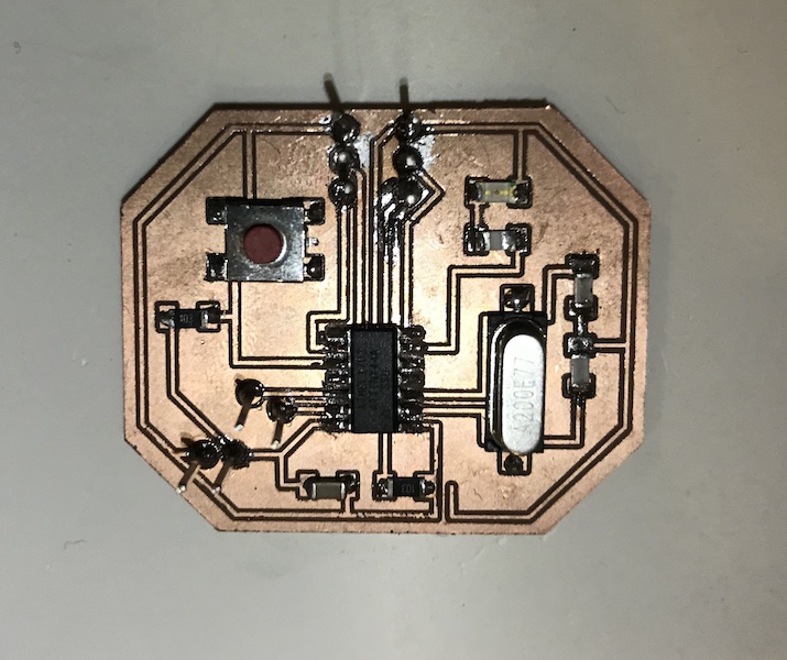
This is the PCB fresh out of CNC
The next step is soldering components onto PCB (Refer to Week4 Assignment for details)
Now that the PCB has been designed, milled and soldered, It is time to program the PCB.
In order to program the PCB, we need to do so through an ISP. We could use the FabISP that we made (Week4) or use an Arduino, I chose the latter.
First we need to connect the Arduino to the PC
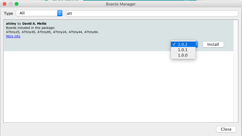
Then we need to download the Microcontroller file in boad manager, (Attiny44) in this case.
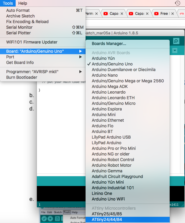
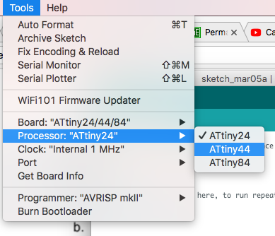
Then select the board the tool tab.
Select which Attiny Processor. (Attiny 44)
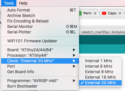
Select the Clock (Crystal SMD Frequency, 20 Mhz in this case)
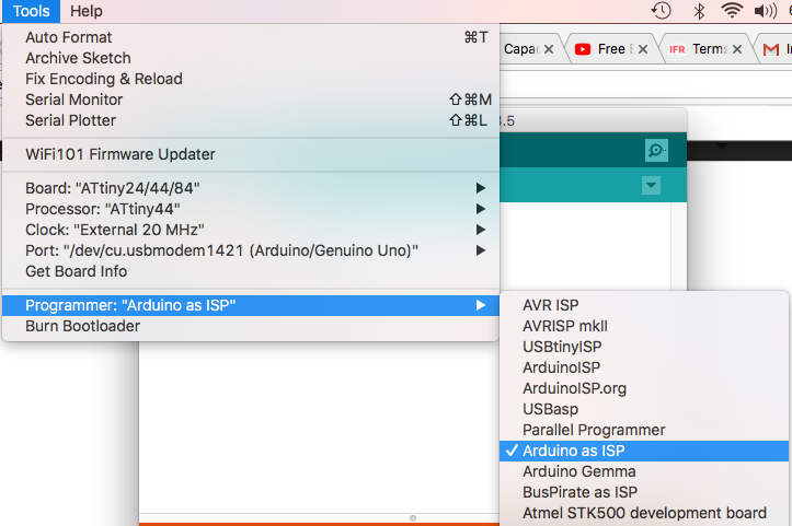
Now under tools, select Arduino as ISP in order to program our new PCB
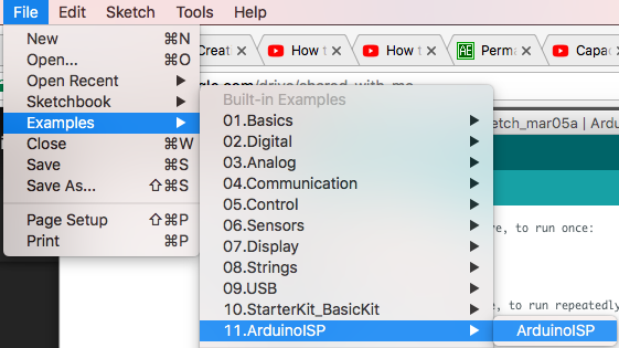
Now under examples, we need to upload the ISP code to the Arduino
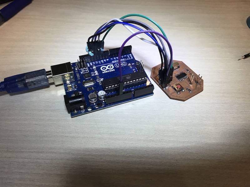
Now that the Arduino is serving as an ISP, it is time to connect our PCB to the Arduino
The connections are as follows:
GND to GND
VCC to 5V
SCK to pin13
MOSI to pin11
MISO to pin12
RST to pin10
And the plug the Arduino back to the PC
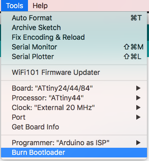
Now under the tools tab, Burn Bootloader
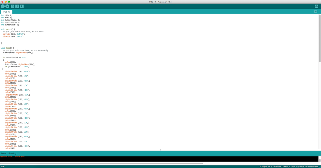
Now it is time to write the code on the Arduino IDEthat the the PCB is going to execute.
I have deigned this code to do two similar tasks based on the input. Since it is my first time programming an arduino I went with something simple and basic yet made the most out of it. Since I had one Button and one LED, I made the LED to flash different Morse codes.
If the button is pressed once the LED will turn on and flash the Letter "G" in Morse code
If the button is pressed twice within a frame of 200ms, the LED will turn on and flash the word "FabAcademy" in Morse code
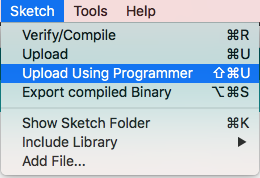
Then Check the Code and Upload it to the PCB through the Arduino Software
Upload the code using the 'Upload using programmer' tool under 'Sketch'
Once everything is set you could just plug in the VCC and the GND and your PCB is ready
Note: Although everything worked out fine, a mistake was done with the addition of the button, a 10K resistor should be added to have a cleaner signal. I was lucky that the pin I associated the button with has an internal pull up resistor called a floating pin that could be activated and solve the issue. To activate the pull up resistor all I had to do was change the code from (button, INPUT) to (button, INPUT_PULLUP).