Discovering the 3D Printers Available in the Fab Lab
- FDM - Fused Desposition Molding This technology is the most commercial technology available in the market. It mainly uses filaments (PLA, ABS, PVA, NYLON..) that are heated and extruded in layers to produce the final shape we need.
- Stereolithography This technology is resin based and it uses a light source to cue the material. It is mainly used for producing small part willhigh precision and quality, usually for the jewelary or dental applications. There are two different mechanisms used for this technology:
- SLA, that uses a Laser Beam as a light source
- DLP, that uses a Projector as a light source
- Slective Laser Sintering (SLS) This technology starts with powder matrial that are melted and binded together using a beam of laser. It is usualy used for building durable functional prototypes with high quality finishing.
- Slective Laser Metal (SLM) This technology starts with a metallic powder matrial that are melted and binded together using a beam of laser. It is usualy used for building metalic parts.
- Inkjet - Material Jetting This technology starts with building material of various colors to produce parts having a variety of colors at the same time.
Assignment
We had a Group Assignment and an Individual Assignment this week.
- Group Assignment The group assginment was to test the design rules of the 3D printers available in the lab. To achieve that, we printed various test parts on the different printers we have in the lab to study the limitations of each and the quality we can achieve.
- Individual Assignment The individual assignment was mainly two parts:
- Design and 3D print an object that could not be made sbtractively
- 3D scan an object
You can check the Group Assignment on the following link: Group Assignment
Machines Used
The main machines used in this week's assignment are the 3D Printers and the 3D Scanner. The list of machines we used are the following:
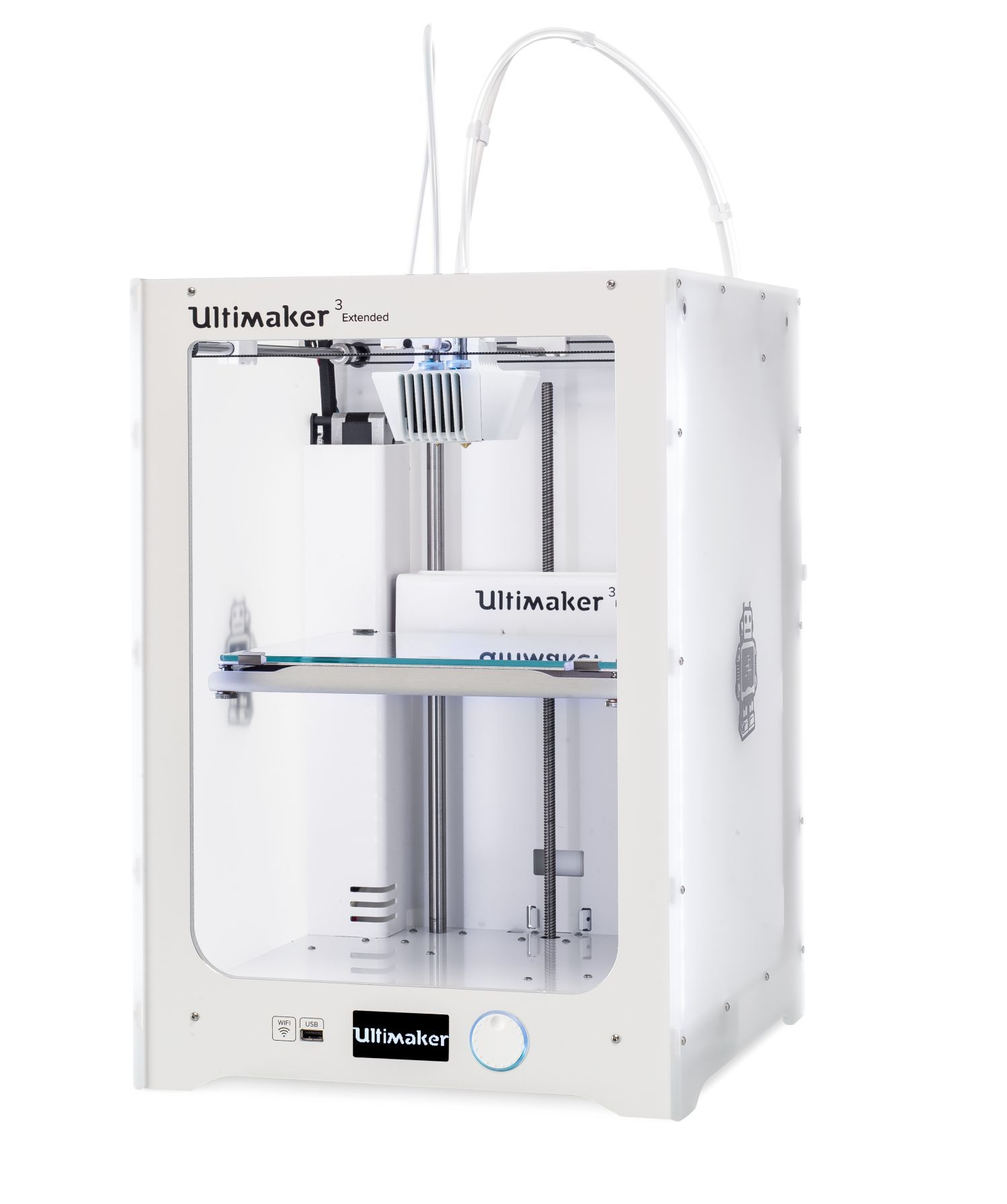
- Ultimaker 3 and Ultimaker 3 Extended is one type of the FDM 3d printers. It was used for 3d printing small scale objects up to 20x20x30 cm.
- Dimensions: 215 x 215 x 200 mm for Ultimaker 3 and 215 x 215 x 300 mm for the Extended
- Layer resolution: 0.40 mm nozzle: 200 - 20 micron
- Build plate: 20 ˚C to 100 ˚C heated glass build plate
- Build plate leveling Active leveling
- Print technology Fused Deposition Modeling (FDM)
- Print head Dual extrusion print head
- Print core replacement Swappable print cores
- Print head travel speed: 30 to 300 mm/s
- Feeder type Dual geared feeder
- XYZ accuracy: 12.5, 12.5, 2.5 micron
- Nozzle diameter: 0.40 mm
- Nozzle temperature:180 ˚C to 280 ˚C
- Nozzle heat up time: less than 2 minutes
- Build plate heat up time: less than 4 minutes
- Operating sound 50 dBA
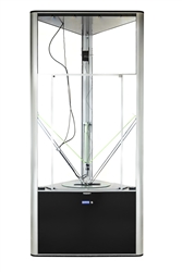
- DeltaWASP 4070 is one of the FDM 3d printers. It was used for 3d printing larger scale objects up to 40x40x70 cm.
- Features & Performances
- layer resolution: 0.05 > 0.25 mm
- precision: X-Y 0.05 / Z 0.01 mm
- print speed: 250 / 400 mm/s
- move: 6.000 / 10.000 mm/s2
- travel speed: 150 / 400 mm/s
- print area: Ø 400 – h 670 mm
- printing volume: 84 liters
- TECH & MATERIALS
- fff filament: Ø 1,75
- materials: abs, pla, hips
- experim.: pet, nyl, flx, pst, pur, lay
- nozzle Ø: 0.4 / * 0.7 / * 0.9 mm
- extruder: porcelain, ceramic, clay
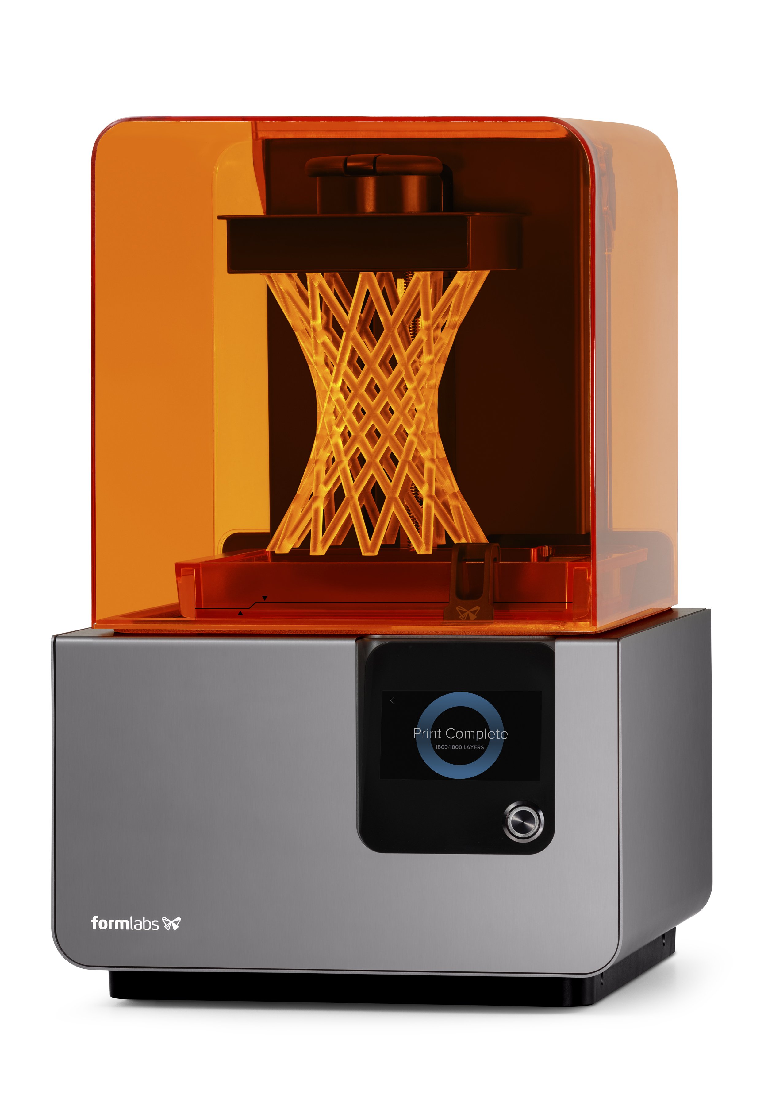
- Form 2 is our SLA 3d Printer. It was used for high-resolution prints.
- Specification
- Dimensions 35 × 33 × 52 cm or 13.5 × 13 × 20.5 in
- Operating Temperature Auto-heats to 35° C - Auto-heats to 95° F
- Temperature Control Self-heating Resin Tank
- Laser Specifications EN 60825-1:2007 certified
- Class 1 Laser Product 405nm violet laser 250mW laser
- Scan in a Box is the 3d Scanner available in our lab. It is used for scanning small objects.
Software Used
The following software were used for 2D Vector Design in this week's assignment:- Fusion 360 was used for 3d modelling in this assignment.
- AutoCad was the main software used for 2D design. I used it to design in 2D and set the dimensions i want to use in the 3d model.
- Cura was the main 3d printing software used in this assignment for FDM printers. I mainly slices any 3d object and generates the gcode that is supposed to run the 3d printer.
- PreForm was the main 3d printing software used in this assignment for the Form 2. I mainly slices any 3d object and generates the gcode that is supposed to run the SLA 3d printer. .
- IDEA 1.1 was the main software used for 3d Scanning and Alligning the various arts of the scan.
1- Characterizing our 3D Printers
In order to discover the limitations of the different 3d printers we have in our lab, and the various qualities we could achieve using it, we decided to make various tests. To undergo the tests, we needed test files that have various variables in one design, where we can check various limitations at the same time.
Preparing Files and 3d Printing
To start 3d printing, we need a digital 3d model of the object we need to print. The 3d printing software usually recieves a 3D model in .stl form as an input, to generate the g-code based on it.
To print anything on the 3d Printer, the follwing procedure has to be followed:
- Building the Design The design, which is a 3d model, can be produced on any 3d modelling software available in the market. This could be anything from Fusion 360, 3d Max, Rhino, 123D Design and many others. The common things between all software is that we have to export the design in .stl form once the design is ready. The .stl form is what the slicer software uses to produce the g-code for the 3d printer.
- Slicing and Choosing the 3d printer's Settings After the design is ready, the next step is to choose the settings we need to produce a 3d printed product having the best result. There are different variables that affect the final product coming out of the 3d printer. Among those variables are the following:
- Layer Height which represents the thickness of each layer in the z-direction, and mainly affects the surface quality of the printed shape.
- Wall Thickness which is supposed to be a multiple of the nozzle extruder
- Infill Desity that controls the density how much the product is filled from the inside.
- Infill Pattern which controls the pattern of the filling inside a body. Different patterns achieve different strengths.
- Printing Temperature which controls the temperature of the nozzle extruding the printed material. Different material have different melting temperatures.
- Build Plate Temperature which controls the temperature of the build plate. This option mainly helps the produced body to stay stuck on the build plate, and it help preserve the temperature inside the build platform thus leading to well adhesion between the layers extruded at each level.
- Print Speed which controls the speed of printing. The slower the speed, the higher the quality we get.
- Generate Support is the setting used to generate support for complicated parts that have unsuported parts at a certain level. Without supports, the extruded material will melt down and lead to a bad quality print. The density and pattern of the support could be also controled. In addtion to the, we can print support using different material than the material of the main body.
- Build Plate Adhesion Type controls how the printed body adheres to the build plate. There are three main adhesion types, mainly skirt, brim and raft.
- Forwarding the Job Order After choosing all the variables, the g-code is produced using CURA the slicing software, which will be saved on a flash drive or a memory card. The flash drive will be inserted in the machine and printed directly on the 3d printer.
Testing the 3d Printers
So the idea was to understand the capabilities and limitations of the different 3d printers we have in our lab. To do that, we wanted to print a test file that has various shapes of different sizes in the same design. The main reason is to check out how the quality of the part will change between different printers.
We used two test file to do the test as one design was not enough to discover all limtiations. The two designs used are the following:
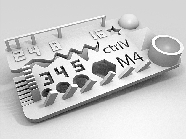
- Test 1 was downloaded from thingiverse.com. It incuded the following:
- size: the object is 2x50x30mm (baseplate)
- hole size: 3 holes (3/4/5mm)
- Nut size: M4 Nut should fit perfectly
- fine details: pyramide, cone, all numbers
- rounded print: wave, half sphere
- minimum distance and walls: 0.1/0.2/0.3/0.4/0.5/0.6/0.7mm
- overhang: 25°/30°/35°/40°/45°
- bridge print: 2/4/8/16/mm
- surface: all the flat parts
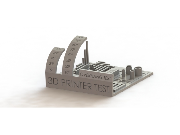
- Test 2 was downloaded from thingiverse.com. It incuded the following:
- size: the object is 100x100x60mm (baseplate)
- cylinder size: 4 cylinders (4/6/8/10mm)
- hole size: 4/6/9mm
- minimum distance and walls: 0.1/0.2/0.3/0.4/0.5/0.6/0.7mm
- overhang 1: 15°/30°/45°/60°/75°
- overhang 2: 10°/20°/30°/40°/50°/60°/70°/80°
- bridge print: 2/5/10/15/20/25mm
- surface: all the flat parts
You can download the original files used for our tests from the following links: Test 1
You can download the original files used for our tests from the following links: Test 2
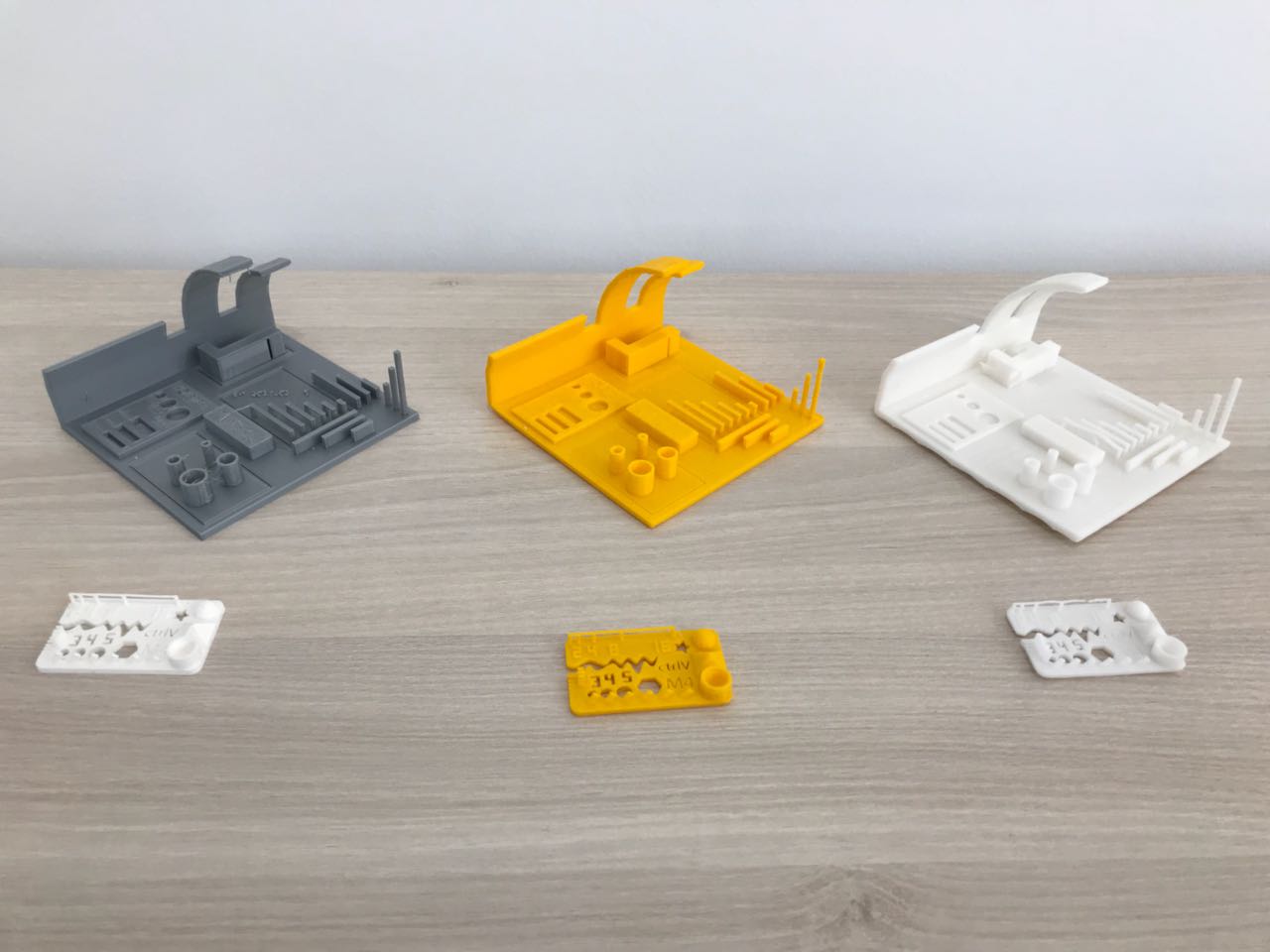
Test 1 Result
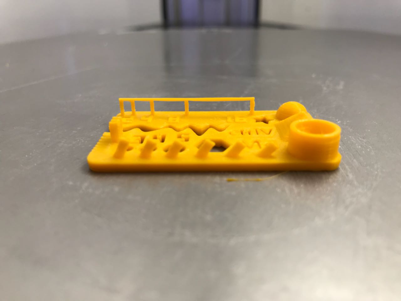
Test 1 - Ultimaker 3
- size: Exactly the same as the design 2x50x30mm (baseplate)
- hole size: the holes have a diameter partailly smaller than the diameter in the design (3/4/5mm)
- Nut size: M4 Nut fits tightly
- fine details: pyramide, cone, all numbers were acceptable with no remarkable misprints.
- rounded print: wave, half sphere were well defined.
- minimum distance acheived: 0.2/0.3/0.4/0.5/0.6/0.7mm
- minimum walls: 0.4/0.5/0.6/0.7mm
- overhang: all angles were successful showing very small irregularities
- bridge print: all bridges were successful
- surface: all the flat parts
Test 1 - DeltaWASP 4070
- size: A bit bigger than the design 2.1x50.3x30.1mm (baseplate)
- hole size: the holes have a diameter partailly smaller than the diameter in the design (3/4/5mm)
- Nut size: M4 Nut fits tightly
- fine details: pyramide, cone, all numbers were acceptable with no remarkable misprints.
- rounded print: wave, half sphere were well defined.
- minimum distance acheived: 0.3/0.4/0.5/0.6/0.7mm
- minimum walls: 0.5/0.6/0.7mm
- overhang: all angles were successful showing some visible irregularities
- bridge print: all bridges were successful
- surface: all the flat parts
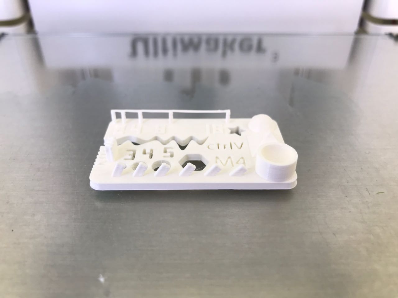
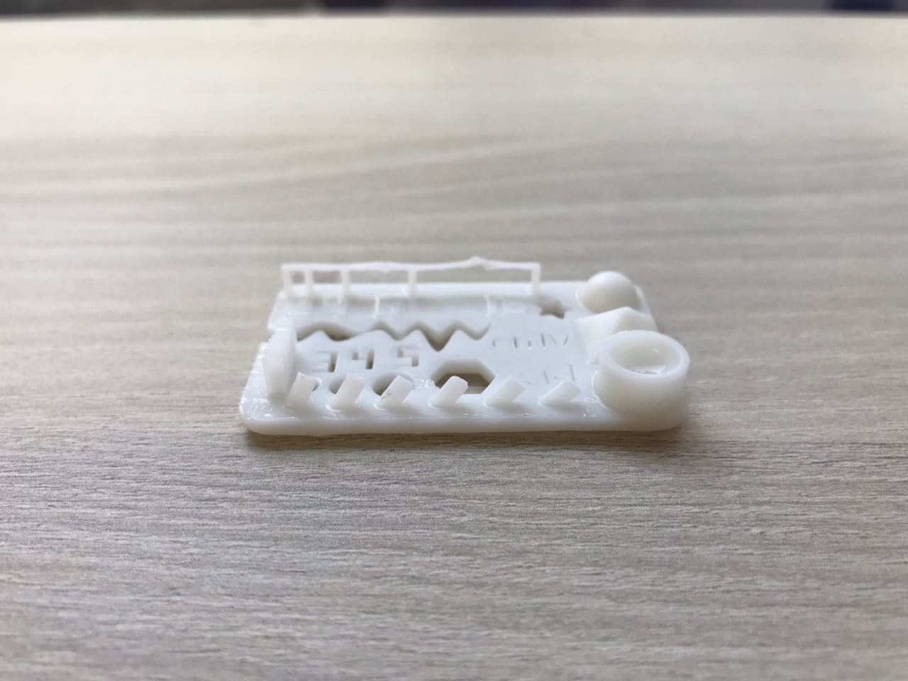
Test 1 - Form 2
- size: the object is exactly 2x50x30mm (baseplate)
- hole size: all holes have the same diameter as the design (3/4/5mm)
- Nut size: M4 Nut fits perfectly
- fine details: pyramide, cone, all numbers were obvious and very clear
- rounded print: wave, half sphere were well defined.
- minimum distance and walls: 0.1/0.2/0.3/0.4/0.5/0.6/0.7mm
- minimum distance acheived: 0.1/0.2/0.3/0.4/0.5/0.6/0.7mm
- minimum walls: 0.3/0.4/0.5/0.6/0.7mm
- overhang: 25°/30°/35°/40°/45°
- bridge print: all bridges were successful except for the 16mm
- surface: all the flat parts
Test 2 Result
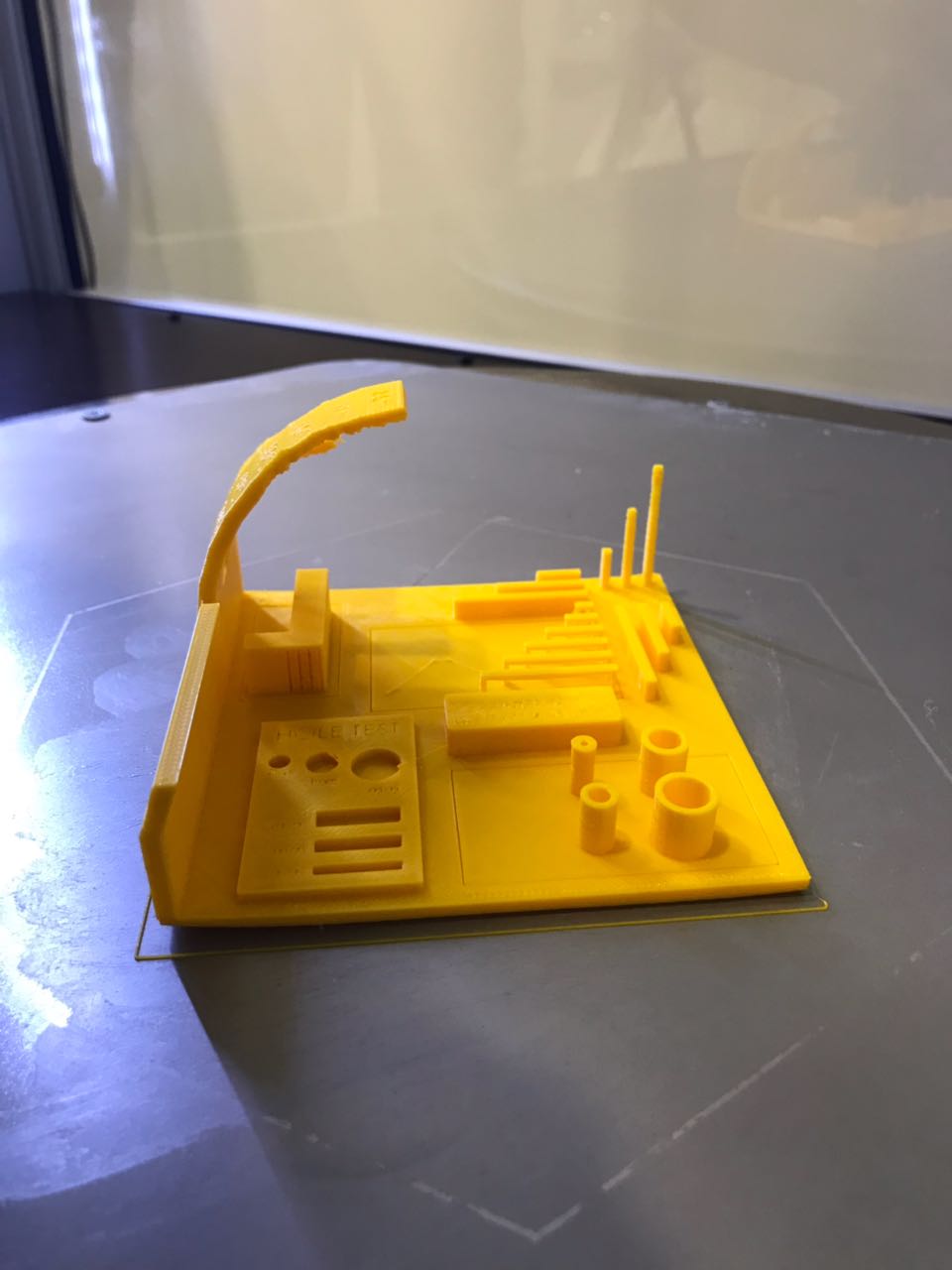
Test 2 - Ultimaker 3
- size: the object has the same dimensions as the design is 100x100x60mm (baseplate)
- cylinder size: the cylinders had sizes slightly smaller than the design (4/6/8/10mm)
- hole size: the holes have a diameter partailly smaller than the diameter in the design (4/6/9mm)
- overhang 1: The following angle were successful having a nice finishing 15°/30°/45°/60°
- overhang 2: The following angle were successful having a nice finishing 10°/20°/30°/40°/50°
- bridge print: all bridges were successful
- surface: all the parts are flat
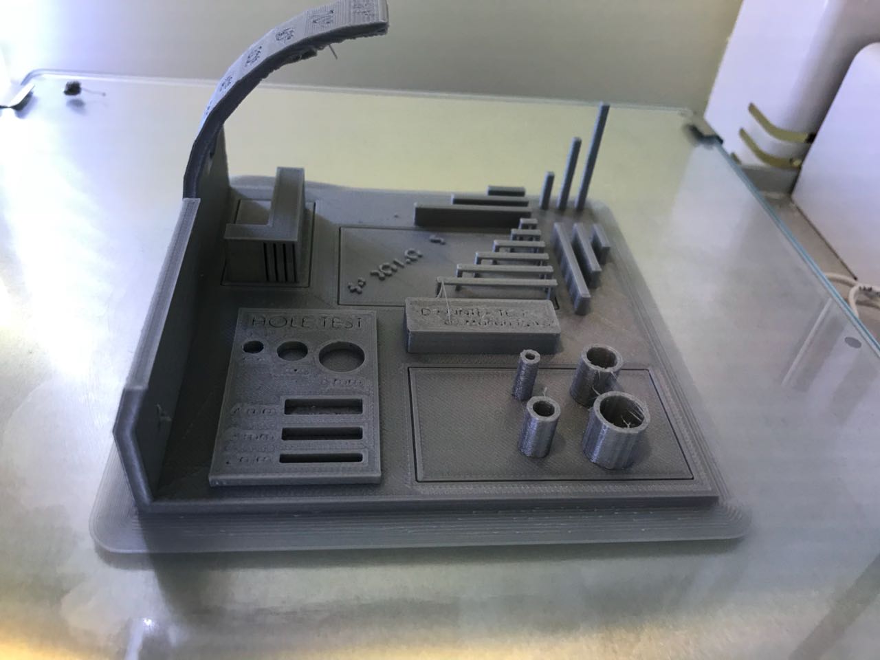
Test 2 - DeltaWASP 4070
- size: the object has the same dimensions as the design is 100x100x60mm (baseplate)
- cylinder size: the cylinders had sizes slightly smaller than the design (4/6/8/10mm)
- hole size: the holes have a diameter partailly smaller than the diameter in the design (4/6/9mm)
- overhang 1: The following angle were successful having a nice finishing 15°/30°
- overhang 2: The following angle were successful having a nice finishing 10°/20°/30°/40°
- bridge print: all bridges were successful
- surface: all the parts are flat
Test 2 - Form 2
- size: the object has the same dimensions as the design is 100x100x60mm (baseplate)
- cylinder size: the cylinders had the exact sizes of the design (4/6/8/10mm)
- hole size: the holes have the same diameter as the diameter in the design (4/6/9mm)
- overhang 1: The following angle were successful having a nice finishing 15°/30°/45°/60°/75°
- overhang 2: The following angle were successful having a nice finishing 10°/20°/30°/40°/50°/60°/70°/80°
- bridge print: all bridges were successful except the 25 mm was a bit deformed
- surface: all the parts are flat
2- Designing and 3d Printing my Design
After testing the capabilities of the different printers in the lab, the next step was to design a shape to be 3d printed, taking into consideration the limitations of the machines.
I wanted to design and 3d print the first prototype for my Final Project, not to waste time and get a physical sense of what it is goinf to look like. I addition to that, i wanted to test the mechanism i had in mind.
You can download the original files used for our tests from the following links: Prototype 1
Step 1 - Designing my prototype.
So the first step is to design the different parts of the robot i have in mind. The different steps of designing the bot are shown in the video.
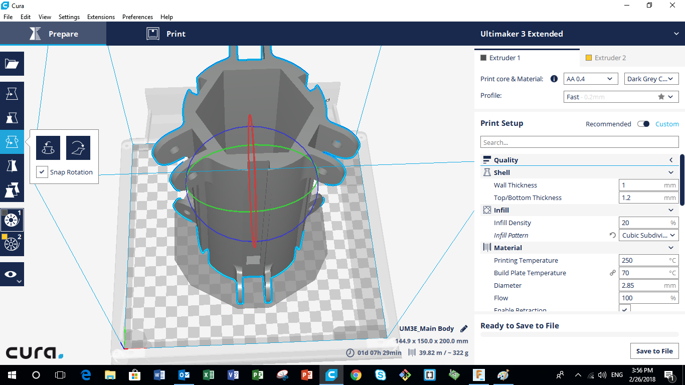
Step 2 - Slicing the Model and Producing the g-code
After producing the digital model, the next step is to slice the digital model into the different layers that will be extruded by the 3d printer. The software mainly slices the design, taking into consideration all the variable we choose in the settings to produce the g-code.
For the main body I used CPE material, as for the legs, i used normal PLA.
The different setting used printing the main body are the following:
- Quality: 0.2mm (Layer Thickness)
- Infill Density: 20%
- Printing Temperature: 250 degrees (because the material is CPE)
- Print Speed: 60mm/s
- Generate Support:ON
- Build Plate Adhesion Type: Raft
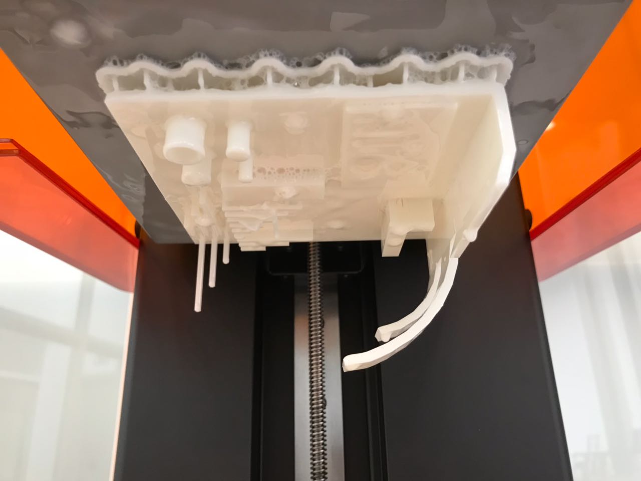
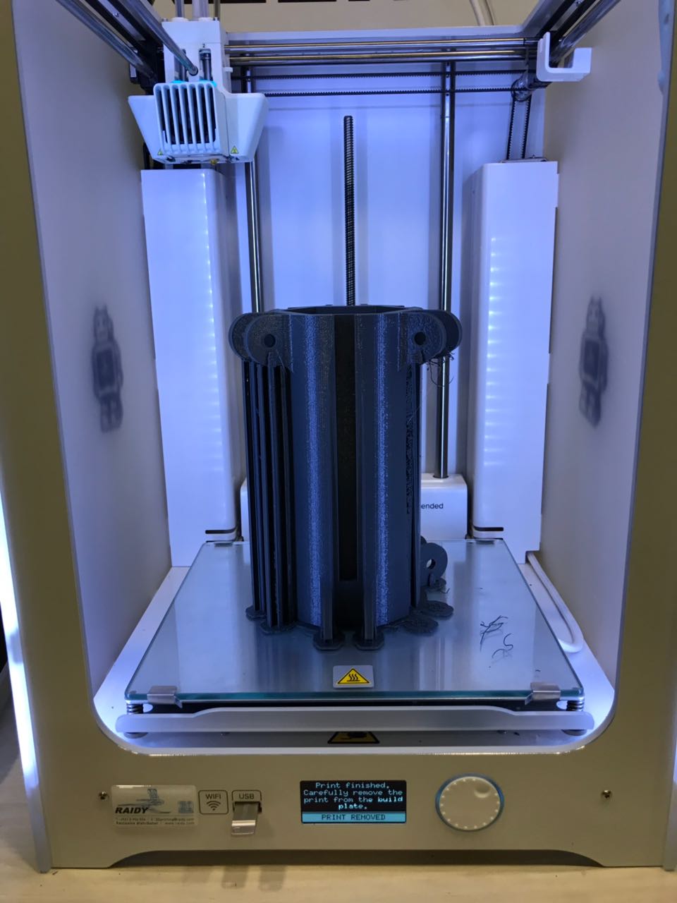
Test 3 - 3D Printing
After producing the g-code on the Cura Slicing software the next step is to save the g-code on a flashdrive and inserting it in the printer. After that, the next stepis very simple, just go to "print" in the options and choose the file you want to print, and then wait for the product to finish. My main body took 1Day 9Hours to be produced with the settings I chose.
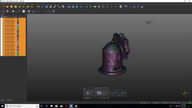
3- 3D Scanning
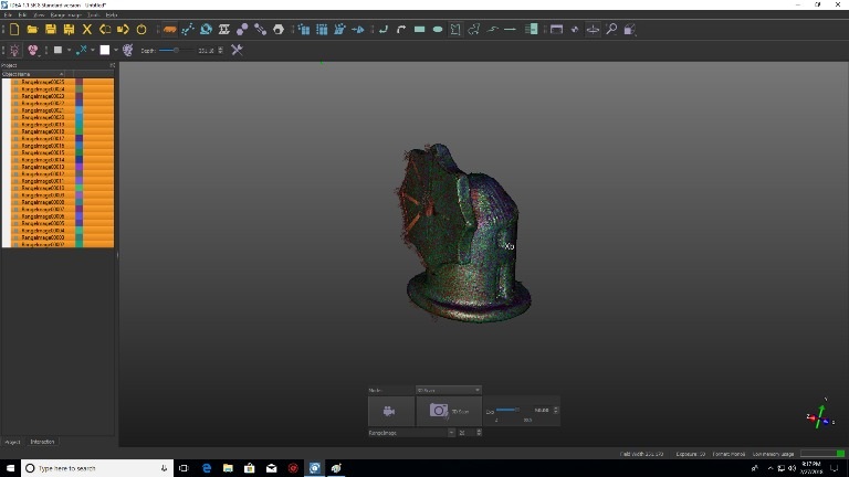
So the assignment of this week was 3d scan anything. So what i chose to scan is a small porcelain sculpture of a windmill.
You can download the original files from the following links: 3D Scanned WindMill
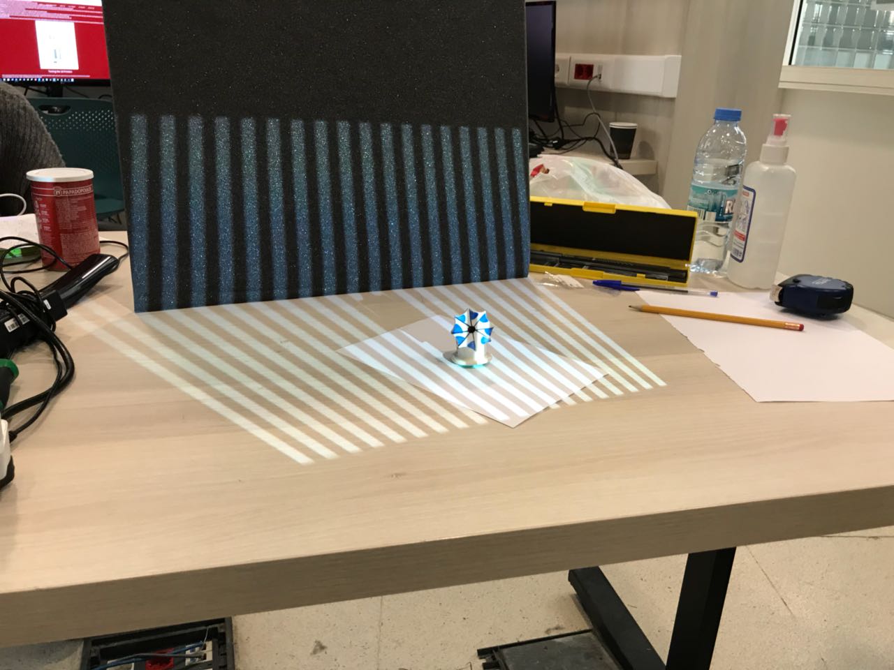
Step 1 - Scan the Body
So the first step is to locate the part on the table where we want to scan and start scanning. The part must be 56 cm away of the light source, and infront of a black background to prefent any noise and distrotion in the scan. The part must be inside the area of the light produced by the projector. Multiple images are taken from various directions after rotating the body partialy for a small angle before each scan. A series of 96 images were used to get a full scan of the tiny body.
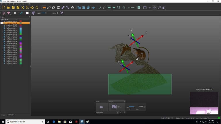
Step 2 - Delete Extra Parts
After doing the scans, the next step is to delete all the parts that we do not want to be included in the scan. Those extra surfaces are mainly the flat surface of the table or anything in the backround of the scanned object.
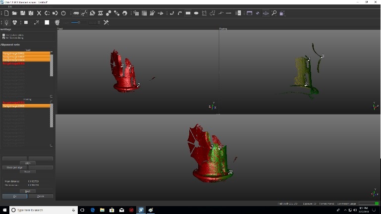
Step 3 - Allign the different parts
The next step is to align the different parts of the body to form one full one. ALigning is done by choosing common points in two different images. After that, the "align" option is used to align precisely and automatically the parts taken from two different images.
Step 4 - Exporting to the final design
After aligning all parts, the next step is to enhance the model and export it into stl file so we can print it later.