Designing my Hello Board
Assignment
We had a Group Assignment and an Individual Assignment this week.
- Group Assignment We had to use the test equipment in our lab to observe the operation of a microcontroller circuit board
- Individual Assignment The individual assignment was mainly two parts:
- Redraw the echo hello-world board
- Add (at least) a button and LED (with current-limiting resistor)
- Check the design rules, make it, and test it
You can check the Group Assignment on the following link: Group Assignment
Machines Used
The main machines and equipment used in this week's assignment are machines that are usually used to produce any PCB. The list of machines we used are the following:
- Roland MDX-40 is the Desktop CNC machine used to mill copper boards.
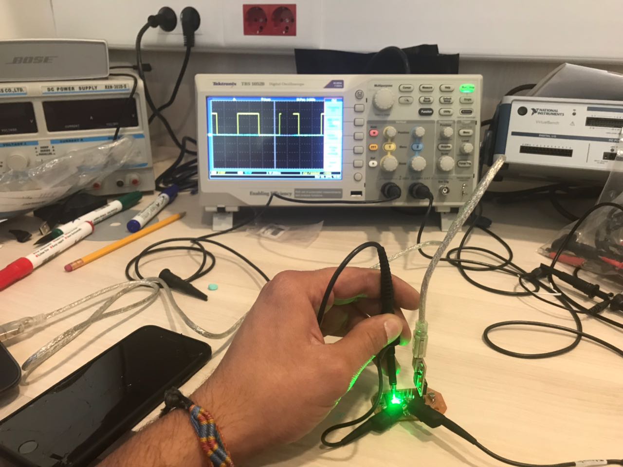
- Tektonix TBS 1052B is the oscilloscope used to observe the operation of the microcontroller circuit board.
- National Instruments VirtualBench was used as a digital oscilloscope to observe and document the operation of the microcontroller circuit board.
- FLUKE 179 was the multimeter used throughout all the process.
- ProsKit SS 207 was the soldering iron used for welding the components.
Software Used
The following software were used for this week's assignment:- Eagle was used to design the PCB.
- GIMP was used to extract and enhance the image of the PCB design.
- Fab Module was the main online platform used to produce the g-code used by the CNC machine.
- Arduino IDE was used to write the code and upload the code the the produce Hello Board.
Building my First Hello Board
So the objective of this week was to learn how to Design and Produce a microcontroller cicuit board. To do that, we needed to learn how to design a PCB, Produce the Board, Program and Test the Board.
To build any PCB in any case, many steps are followed to achieve that. Those steps will be discussed in details in this section. The steps go as the following:
- Designing the Circuit and Sketch of the PCB
- Extracting the images for the Internal and External Paths
- Generate g-code using Fab Modules
- Mill the PCB
- Weld all the components
- Write the Code
- Upload the Code to the Board
- Test the Board
Step 1 - Designing the Circuit and Sketching the PCB
The first step in any PCB production process is preparing the design. There are many software availablein the market that are used for PCB design. Some of those software are the following:
In my case, i chose to use Eagle as it is a very nice software to build electric circuits and design the connections on the PCB.
In order to start designing my PCB, i first started with the available design of the echo hello-world board.
The design of the eco hello board is shown in the image below and available on this link.
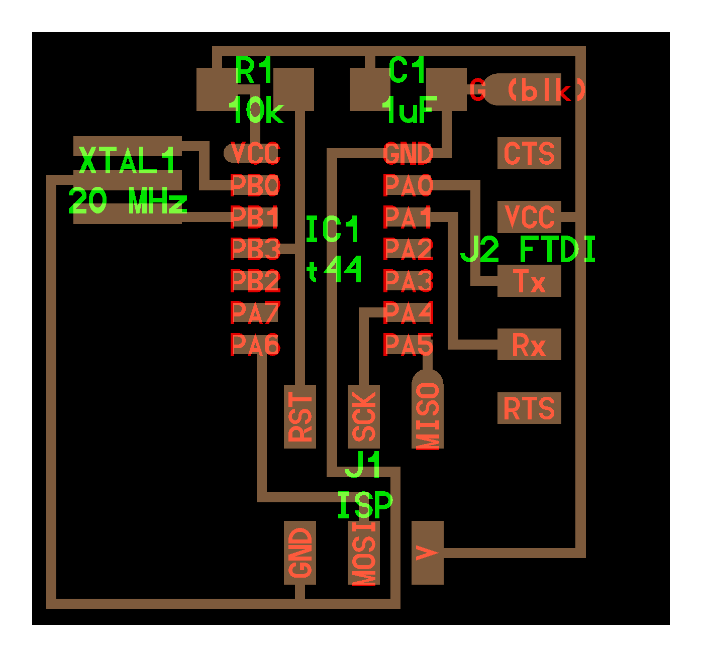
The components available in this design are the following:
- ATiny44A is the microcontroller used in this cicuit
- 1uF Capacitor
- 10 Koum Resistor
- FTDI Pin Headers
- ISP Pin Headers
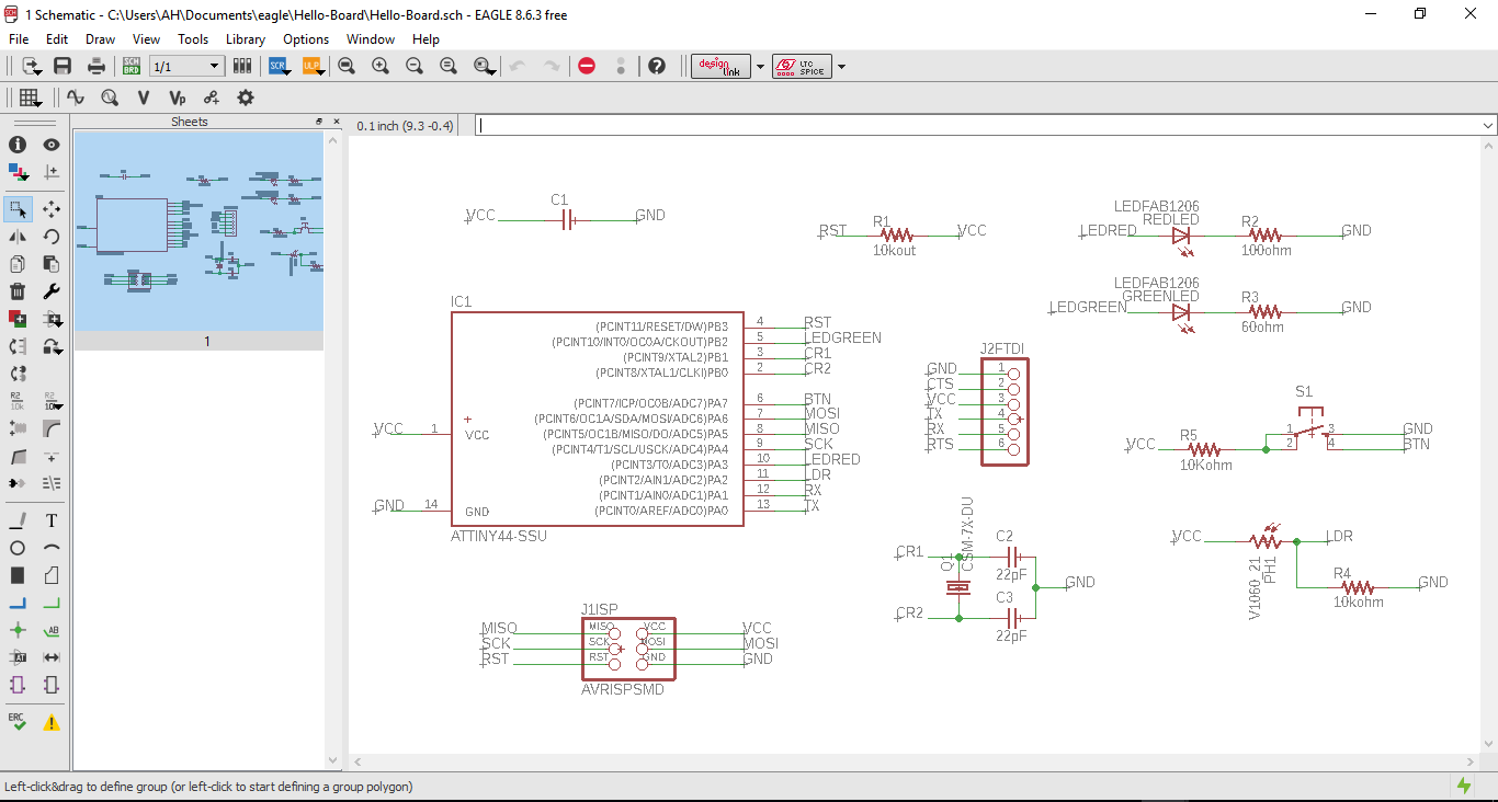
However, the assignment was to add more components and functions to the circuit. I chose to make something functional and dependent on the surrounding, and not just a simple LED controlled by a button.
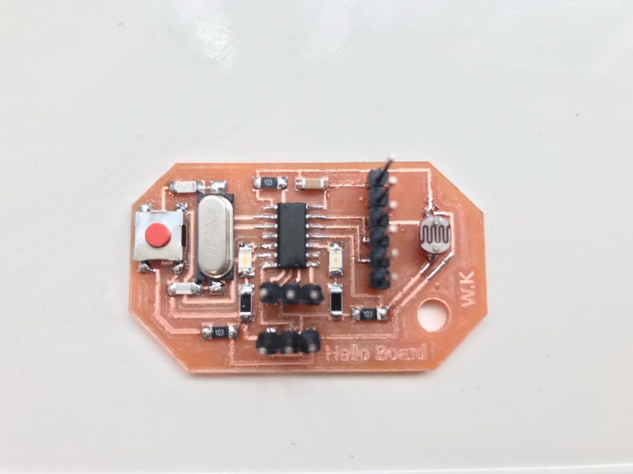
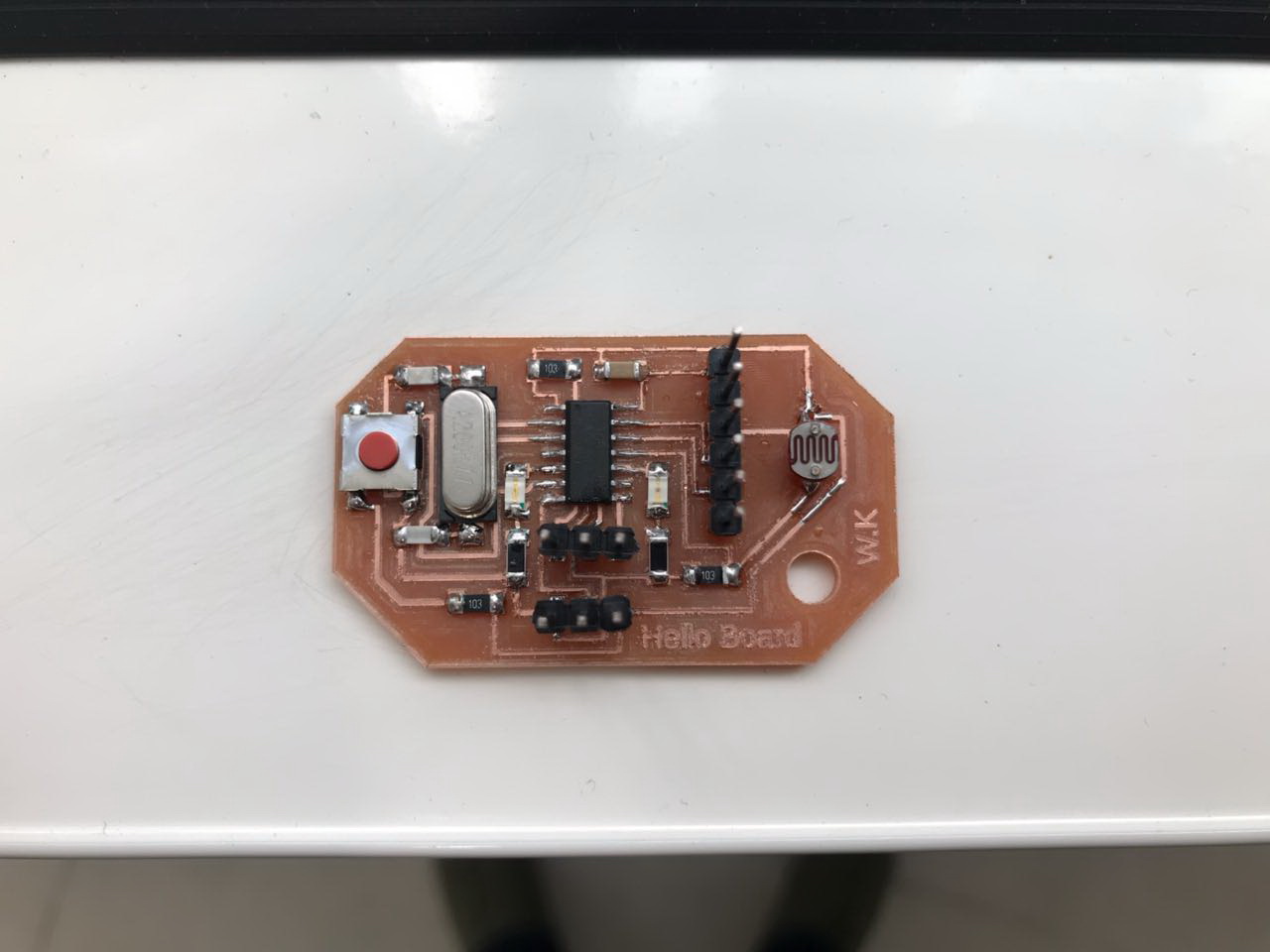
So my idea was to design a board that has 2 LEDs of different colors, one Red and one Green, in addition to a Photoresistor (LDR) and a Button. The objective of the board is to measure the light intensity and based on that, the LEDs will turn on. The Green LED will turn ON when there is light and the Red LED will turn on when there is darkness. Note that the frequency of the LEDs flash depends on the intensity of Light or Darkness measured by the LDR. The more the light or darkness, the faster the blink of the LED.
So additional components were needed to build my intended system. The components added to in this design and thier Data-Sheets are the following:
The data-sheet is mainly used to understand the capabilities and limitations of a component, and understand the best way to connect it. From the data sheet, you will know what additional components are needed to make the component functional. So from the data sheets of those components, we deduced the following:
- Red Led:We need a resistor in series with the Red LED greater than 100ohms To calculate the resistor needed for a simple LED circuit, simply take the voltage drop away from the source voltage then apply Ohm's Law. In other words...LED Resistor Formula: R = (Vs - Vled)/Iled = (5-2.4)/0.03= 86.6 ohms
- Green Led:We need a resistor in series with the Green LED greater than 60ohms To calculate the resistor needed for a simple LED circuit, simply take the voltage drop away from the source voltage then apply Ohm's Law. In other words...LED Resistor Formula: R = (Vs - Vled)/Iled = (5-3.8)/0.03=120 ohm
- LDR:A 10K ohm resistor is connected along with the LDR, and the signal going to the pin is measured from in between.
- Push Button: the pins on the same side of the switch are connected together
Adding Libraries on Eagle
So the first stem before building any circuit is to choose our components that are required.
But components are not always available on Eagle, and to make them available, we need to add some Libraries that are prepared by others and available on the internet as open-source.
In my case i downloaded the Fab Libarary that is found on the Fab Academy Archives.
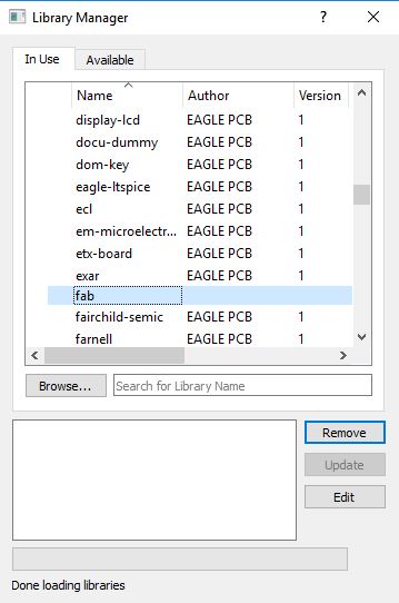
Next i inserted the Library into Eagle. To do that follow the following steps:
- Press "Library" from the toolbar
- Press "Open Library Manager" from the drop down menu
- Browse for the downloaded library that you want to add under the "Available" part
- Press "use" and now you have added the library
Re-Drawing the Echo Hello-World Board
So the second step in my design was to re-draw the echo hello-world board based on the component we need to achieve the basic circuit. To do so, we start by adding the components we need on the Schematic part of the software.
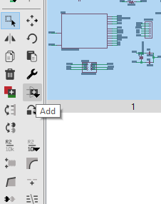
To add components on Eagle, use the "add" button as shown in the image, and choose the components you want.
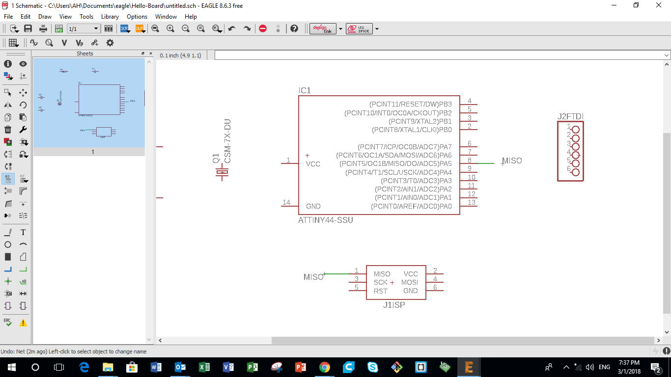
Connecting all the components together
Next we need to connect the added component togather, based on the best connections according to the data sheets. So in order to connect components, the following steps are followed:
- Using the "Net" button, draw wires from all the pins that you want to connect on the different components
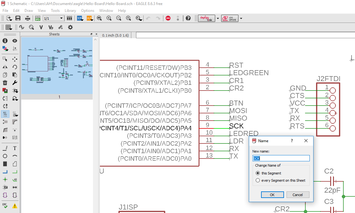
- Using the "Label" button, add a label to the wire and name it with and abrevation of the name of the component
- Using the "Label" button, add another label the the pin that needs to be connected on the other component, and name it with the same name you used for pin of the previous component
- Next press "Ok". The software will ask you if you want to connect the pins. Press yes and the pins are now connected
Adding My New Components and Connecting them
After re-drawing the circuit of Echo Hello-World Board, the next step is to add the components i want in my circuit. The best way to connect the components was deduced from the data sheet of each component.
To add components on Eagle, use the "add" button, and then go to the Fab library and choose the component that you need.
Next connect all the components using the method described in the previous step.
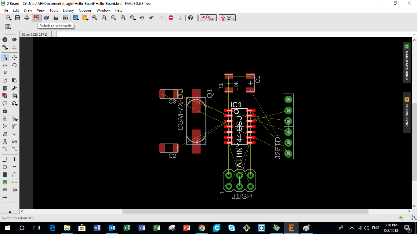
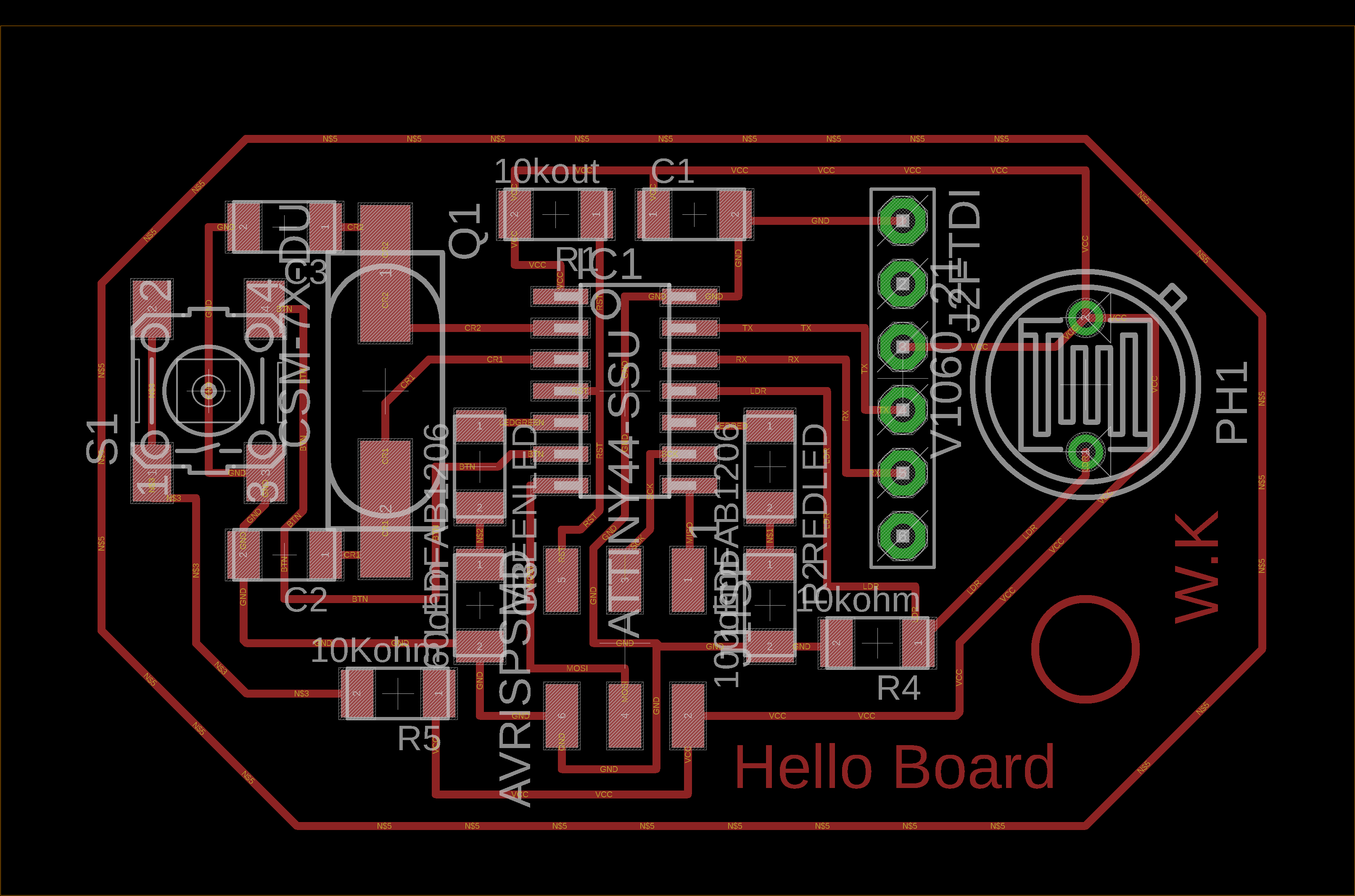
Organizing the Board Schematic
After connecting all the components on the board, the next step is to organize the schematic of the components. This schematic represents the location of the components on the board and the path of the connection in between the components. This step takes time and requires some art and concentration. During this level, the following points must be taken into consideration:
- The connecting lines have to be more than 12 in width
- Different connecting lines must not overlap, otherwise a short circuit will occur
After finalizing the design and location of all components, using the "Line" function, draw the external parameter of the Hello Board that will be used to mill the external traces of the board.
You can download the original Eagle design files for My Hello Board from the following links: href= Hello-Board.zip/>Hello-Board
Step 2 - Extracting the PCB Schematic Image and Enhancing on GIMP
Extracting the Final PCB Design in PNG format
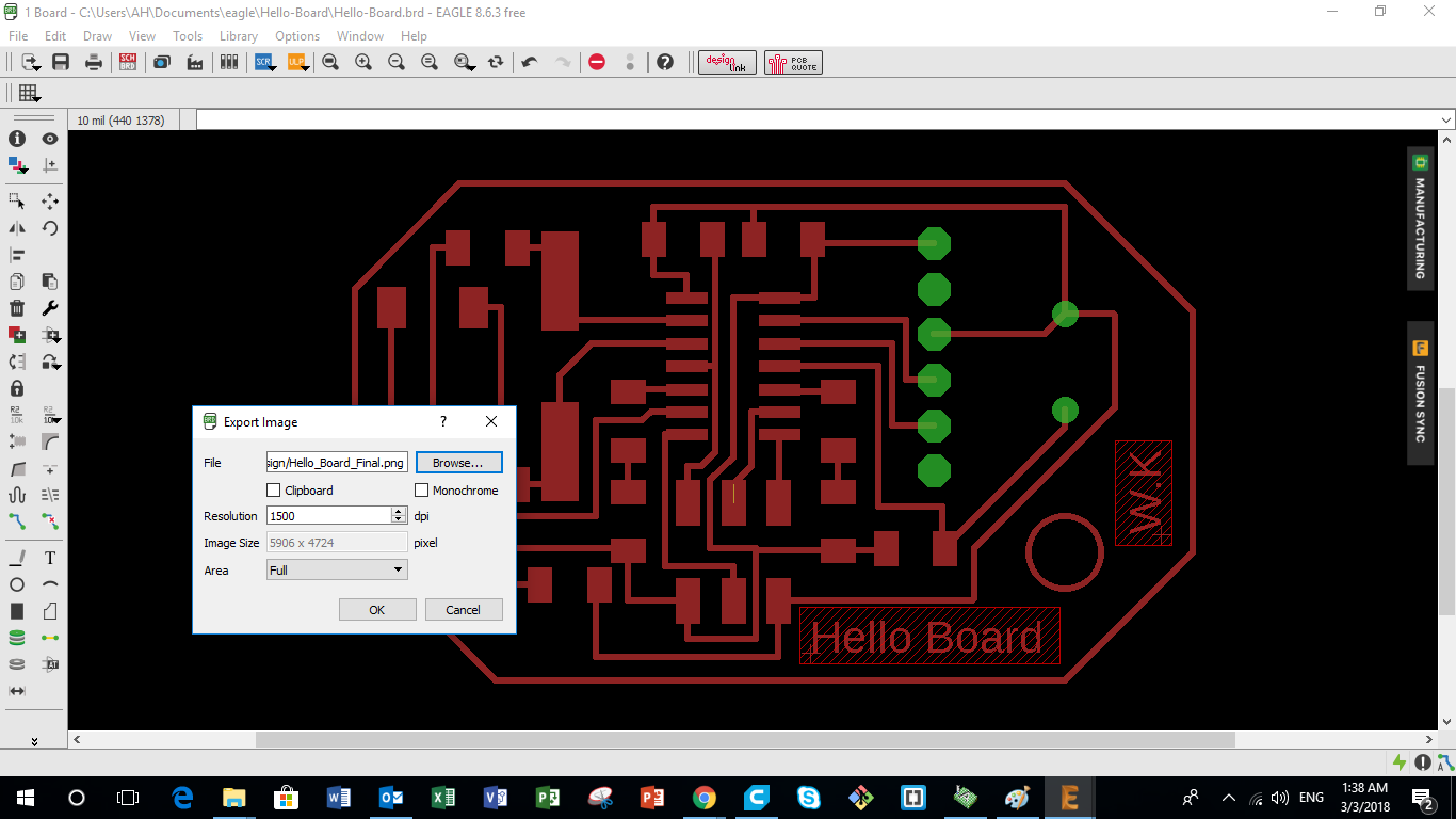
After finalizing the layout of the PCB on Eagle, we want to extract the image that represents the PCB design. To do so we need to follow the following steps.
- First we turn off all layers by following the following path "view" > "layer settings" > "select none"
- Next we turn on only the layers we want to appear, mainly the ones we need to stay on the copper board during the milling process
- Extract the image in a monocrome form
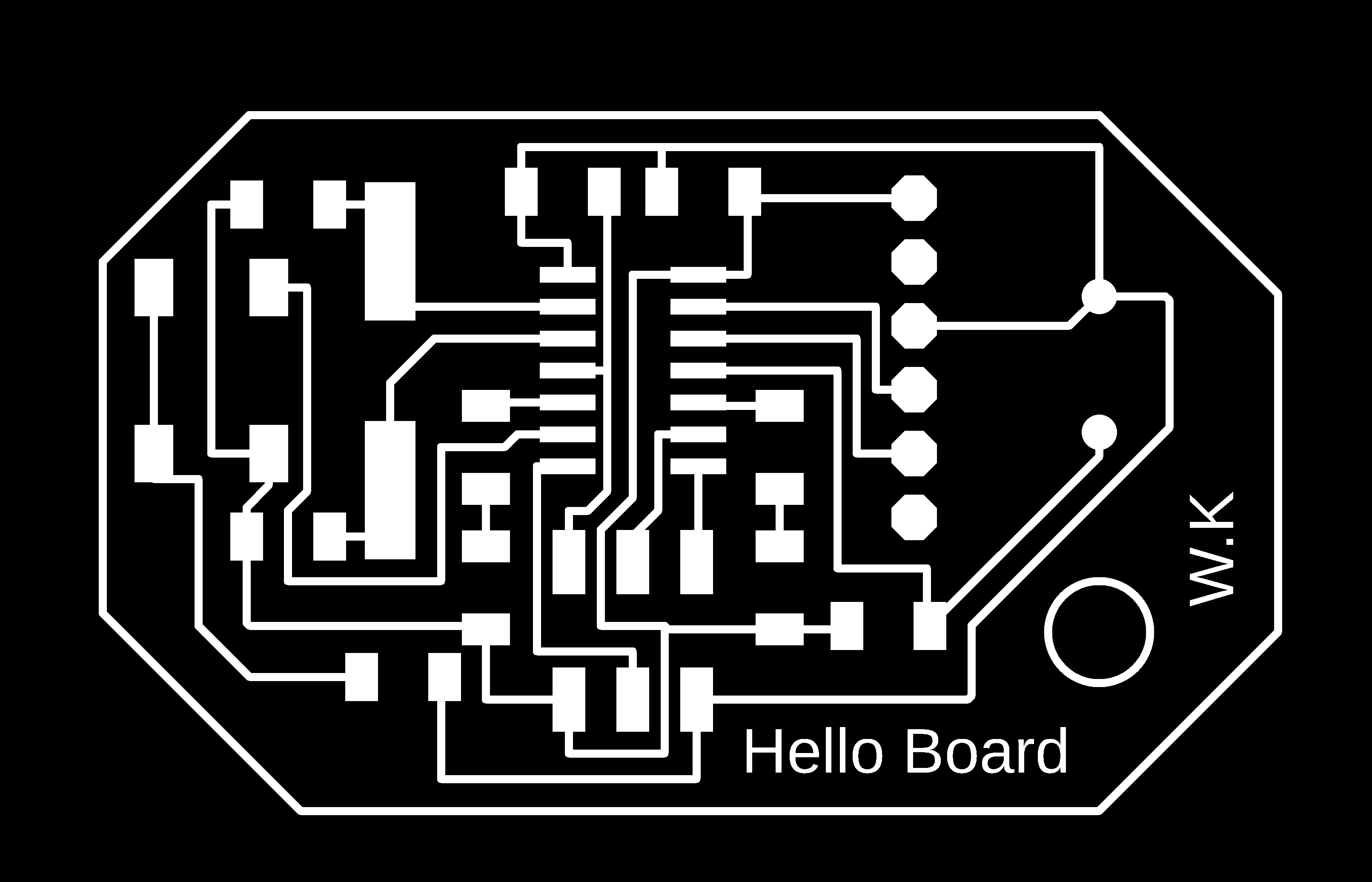
Please note that in my board, 2 different images needed to be extracted, and the same process had to be done 2 times. One image represents all the paths of the connections between the components, and the other represents the position of the drilling positions.
You can download the extracted images for My Hello Board from the following links:
Exporting the Image to GIMP and Extracting the internal paths
So the next step after extracting the image from Eagle is to produce the images we need to use on Fab Modules to generate the g-code later.
So first we open the original image from Eagle and "save as" a new copy that you can edit. Call the first image "internal path".
Using GIMP is easy, just fill the area you dont want with black and that's it. I produced 2 images for the internal path to be used in fab modules. The images are the following:
- Internal Path represents the internal path of the PCB
- Drilling Positions represents the drilling positions of the PCB
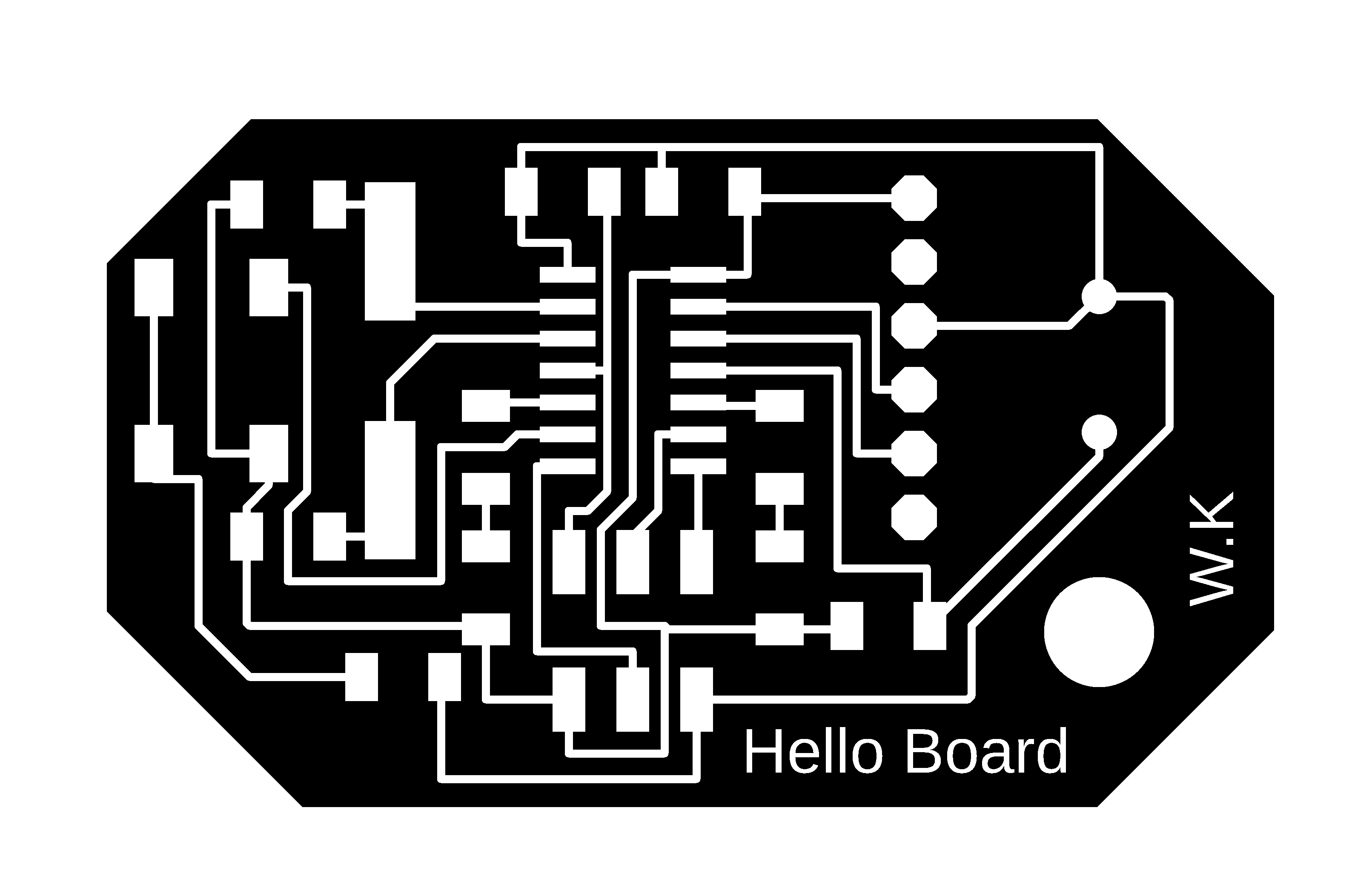
Extracting the External Path
So the next step after extracting the internal paths is toextract the images of the external path we need to use on Fab Modules to generate the g-code later.
So we open the original image from Eagle and "save as" a new copy that you can edit. Call the first image "external path".
Using GIMP is easy, just fill the area you dont want with black and thats it. I produced 1 image for the internal path to be used in fab modules. You can download the image from the following link:
Step 3 - Generate the g-code using Fab Modules
Procuding the g-code
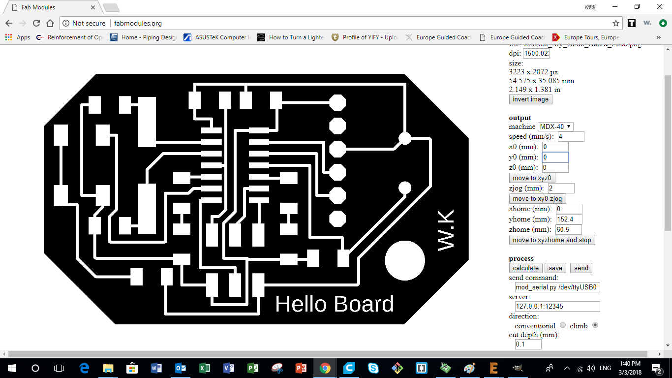
After extracting all images that represent the internal and external paths of the milling bit, it's time now to produce the g-code. I used Fab Modules to produce the g-code for PCB milling on the ROlang MDX-40.
The following steps were followed on Fab Modules to generate the g-code:
- Choose input format and select image (png) that the g-code is going to be generated from
- Then select the file from the specific folder
- Then go on to Output format and select the format that applies to the CNC machine you are using, in our case it was Roland mill (.rml)
- Then select Process and choose PCB traces (1/64) for internal paths and PCB Outline (1/32) for the external parameter
- Then under Output, select the CNC machine you are using, it was a Roland MDX-40. Change the X0, Y0 and Z0 to save space on copper board used. Then check the Feed Speed. I was using 4mm/sec for the Internal Traces and 0.5mm/sec to the External Parameter and Drilling
- Then Under Process, adjust the cut depth which should be 0.0 mm for the internal tracing, and 1.7mm for the external parameter and drilling. The tool diameter (milling bit) which was 0.1 mm for the internal traces, 1 mm for the external parameter, and 0.8 mm for drilling.
The Number of offsets used was -1 which will lead to removing everything in black and only keering the paths that we need. The offset overlap used was 70%
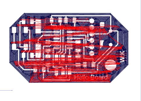
No other adjustments were be made. - Once the Input, Output, and Process tabs are double have been adjusted and double checked. Go ahead and press the Calculate button
- Then finally click the Save button and save it to the designated folder. It would be saved as an .rml file
Step 4 - Milling the PCB
So the next step after producing the g-code is to forward the job to the CNC machine and perform the milling.
CNC Milling the PCB Board
After preparing the G-code, the following steps were taken to mill the layout onto the copper board:
- First I needed a software that would send the g-code directly to the Roland MDX-40. In my case I used the Drop-Out software to send the .rml file to the CNC machine
- On the Drop-Out application press the add button and choose the .rml file you created and press open
- Then go to File and select Print Setup
- On the Print setup first choose the name of your printer, in my case it was the Roland TS-30
- Then go to Properties and press the Tool tab, the only thing that should be adjusted are the Z down position and Z engraving pitch both should be at 0.00 mm. During the milling the RPM used was 10,000 for all jobs
- Then go on to the Options tab and select Operation Panel
- Set the X and Y-axis on the position where you want your PCB to be engraved on the copper board inside the CNC, then press the XY axis SET button
- As for the Z-axis, we needed to zero the tool at the top surface of the copper board. In order to do this delicate process we need to gradually bring it down onto the board, with the help of a multimeter with the beep mode on and have one of the cables on the copper board and the other on the drilling bit. In this case as soon as the drill-bit touches the copper board the multimeter would beep. Make sure to go extremely slow at the end so you dont risk breaking your drill-bit
- Once the beep is heard, you know that the drilling bit is right at the surface and you can go back to the operational panel (on Drop-out), select the Z-axis from the dropdown menu and set the Z-axis.
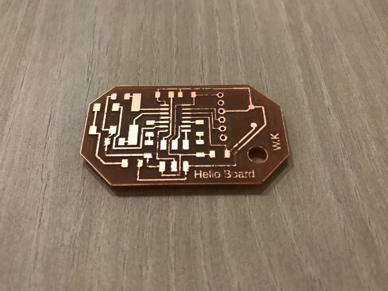
- Once everything is set press OK until you reach the first page of drop-out and press theOutputbutton. Your CNC machine should now start the process of milling/engraving the copper plate set inside. watch the process until its done
- Check the final result, using a multimeter with the beep setting to make sure components are isolated and all conductivity channels are connected
Step 5 - Weld all Components on PCB
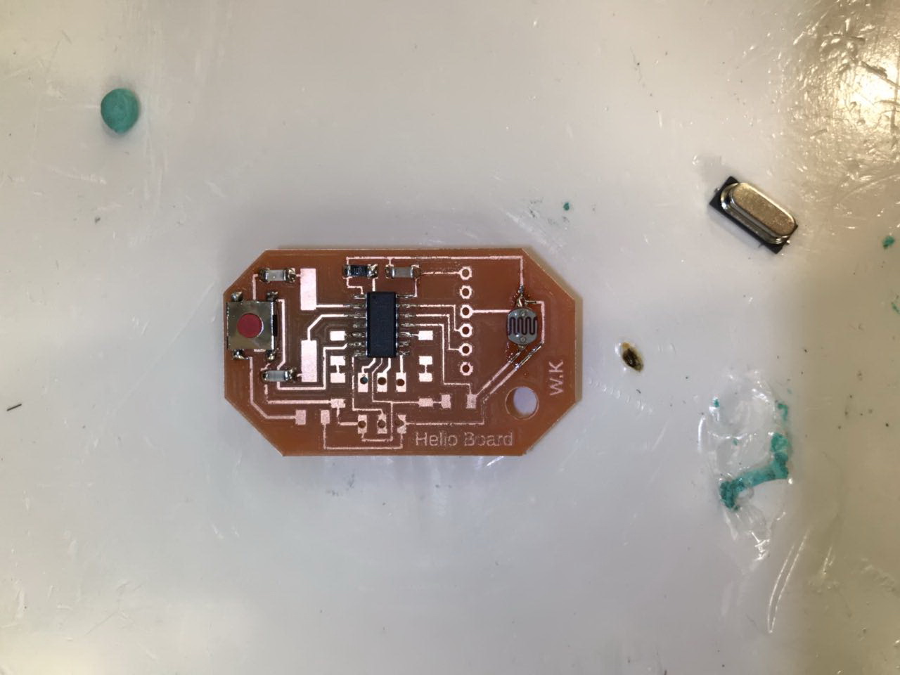
So the next step after milling the copper board, is to weld all the component needed in this cicuit.
Welding Components
Now that we have the PCB layout cut-out, the next step is to start soldering. In order to do so we first need certain tools to proceed, find the list with specs below:
- Soldering Iron: set at 320 degrees celcius
- Solder wire: 0.5 mm
- Tweezers
- Desoldering copper
- Vacuum
- Tack-it
The following list represents the list of components used in My Hello Board:
- Atiny44A Microchip
- 1 x 20 MHz Crystal
- 2 x 22pF Capacitor
- 3 x 10 Kohm Resistor
- 2 x 499 ohm Resistor
- 1 x Red LED
- 1 x Green LED
- 1 x LDR
- 1 x 4-pin push button
- 1 x 6-pin FTDI pin headers
- 1 x 6-pin ISP pin headers
Now for the final step in this process, make sure all connections are ok using the multimeter on the beep option. And you should be set to move on to the next step.
Step 6 - Write the Code
So after getting done with the hardware part of the cicuit, it is time to write the code that will control the circuit.
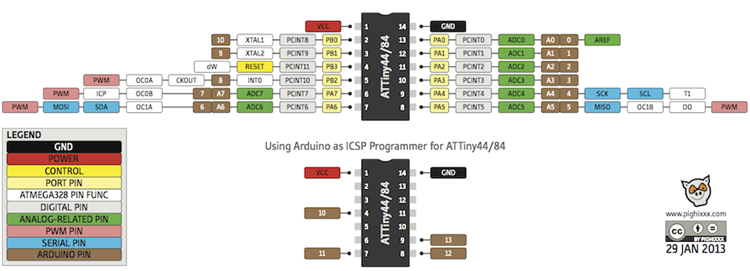
Because i was using the Arduin IDE to write my code that i will be using on my hello board, i used the Attiny44 pinout diagram to understand the pins and know how to assign the pins in the code.
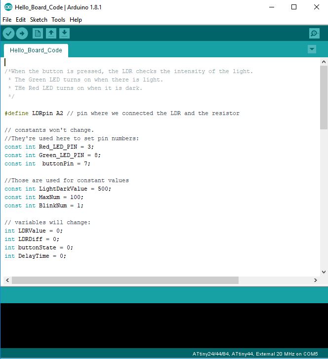
Writing the Code Using Arduino IDE
In order to measure the light intensity using the LDR and cotrolling the LEDs, we need to right a code that does that exaclty.
So my code mainly measures the light intensity using an Analog Input. The measured value will then be compared with the light/dark threshhold set by me in the code, and based on that the delay time is calculated to control the frequency of the LEDs flashing. If there is light, meaning that the LDR value is high, the Green LED will blink at a frequency depending on the strength of light. On the other hand, if there is darkness, meaning that the LDR value is low, the Red LED will blink at a frequency depending on how dark it is.
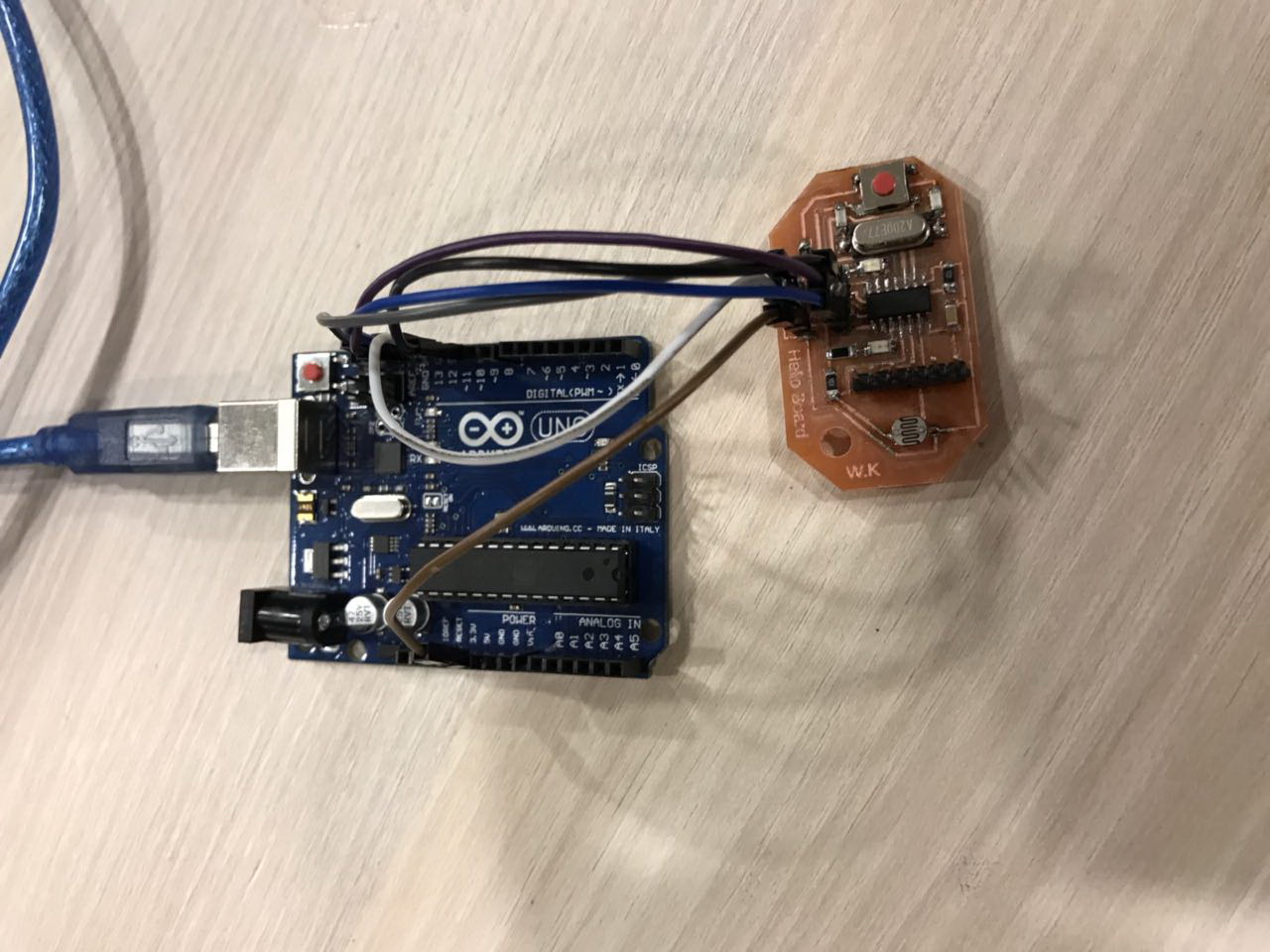
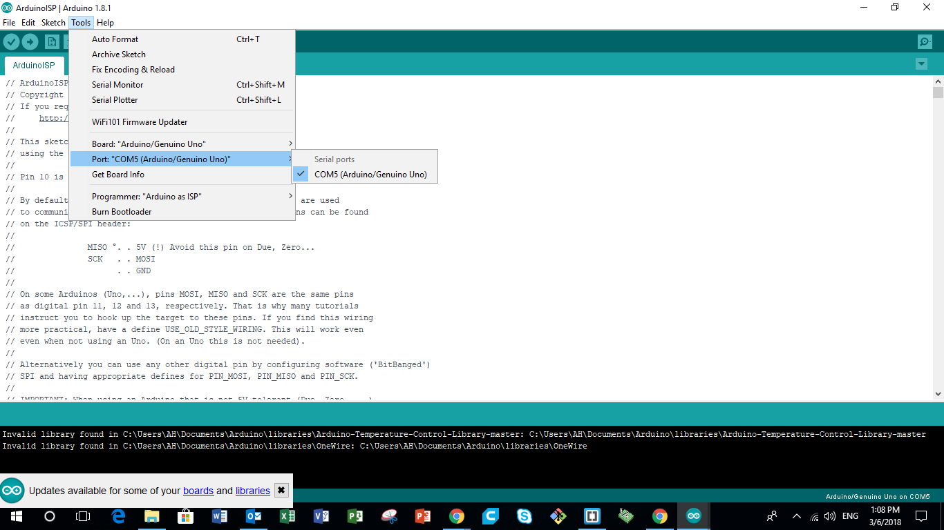
Step 7 - Upload the Code to the Board using Arduino
