Discovering How to Program an AVR Microcontroller
We had a Group Assignment and an Individual Assignment this week.
- Individual Assignment The individual assignment was to:
- Read a Microcontroller Data Sheet
- Program my board to do something using different programming languages and programming environment.
- Group Assignment The group assginment was to compare the performance and development workflows for other architectures.
You can check the Group Assignment on the following link: Group Assignment
Machines Used
No machines were used this week other than the computer, a coder's best friend.Software Used
The following software were used in this week's assignment:- Arduino IDE was used for building the code and uploading it to the microcontroller.
- NOOBS was used to download the operating system on the RaspberryPi Board. NOOBS is an easy operating system installer which contains Raspbian. It also provides a selection of alternative operating systems which are then downloaded from the internet and installed.
- Python is a wonderful and powerful programming language that's easy to use (easy to read and write) and with Raspberry Pi lets you connect your project to the real world..
1- Reading a Microcontroller Data Sheet
When building any electronic system or a cicuit board, the first thing we should know is to undertand the capabilities and the capacity needed to opperate all the components in the circuit. Next we have to choose the Microcontroller that would achieve the capabilities that we want. To do so, we need to read and understand its Data Sheet, to check its capabilities and later know how to program and control it. Thus it is very important to be aware on how you can read a data sheet and extract the information that we need to be able to connect and code the microcontroller.
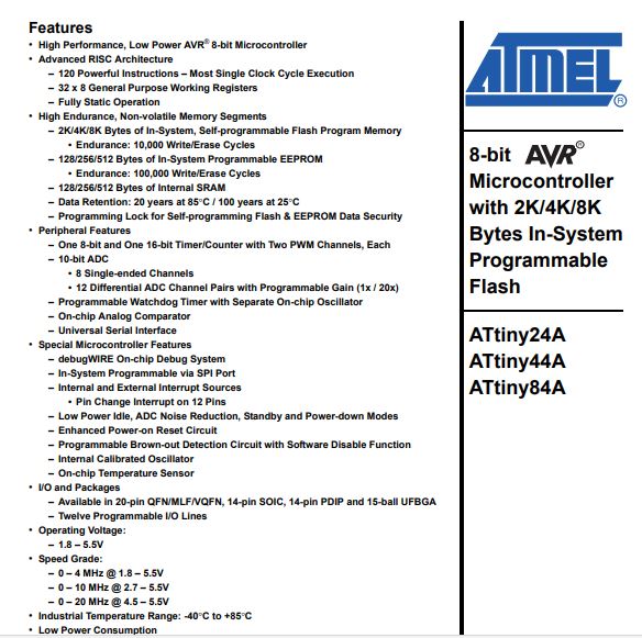
So in my case my Hello Board was designed and produced based on the Attiny44 microcontroller. So i had to read the DataSheet for the ATtiny44 to know on which pins I have to connect my components, and understand how i need to write my code.
Attiny is produced by Atmel company and have many advantages like:
- Small Size
- Fast and Code Efficient
- High Integation
- 0.7 V operations
1- Pin Numbers and Choosing the Port
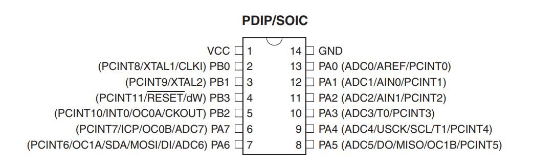
So the first thing i have learned from the datasheet is the number of pins on the ATtiny44 Microcontroller.
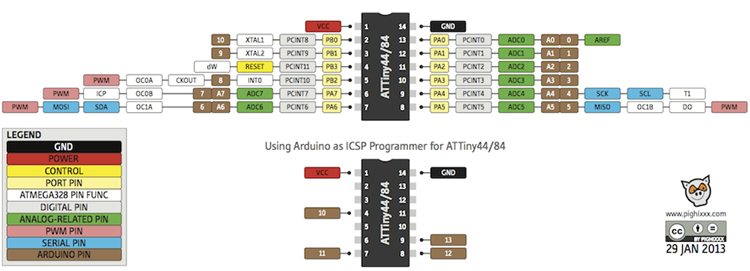
The ATtiny44 has 14 pins. Those are very important to understand how to design our PCB and how to refer to the pins in the code.
The pinout diagram is shown in the image.
So the micro-controller have one pin for the voltage VCC and one pin for ground GND so I can connect external power to it if I want to use it separately without using usb port of the computer, it also have 8 pins related to data register A DDRA and 4 pins related to data register B DDRB, PB3 can be used as the pin for reset.
One of the advantages of the Attiny is that it contain pull up resistor that I can use when i need it.
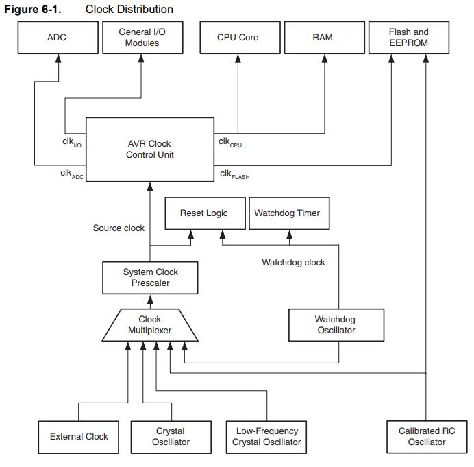
2 - Clock of the Microcntroller
By learning the principles of how to use the clock I will know the basics of connecting my resonator in the circuit.
This image show the clock distribution in the micro-controller.
There are two types of clock internal clock and external clock.
I will use is the external clock as I will put oscillator on all boards I will use as the intranal clock have an oscillator of 8 mhz and I decide to use 20 mhz.
The ATtiny24/44/84 system clock can be divided by setting the “CLKPR – Clock Prescale Regis- ter” . This feature can be used to decrease power consumption when the requirement for processing power is low.
This is the code of activation.
CLKPR = (1 << CLKPCE); CLKPR = (0 << CLKPS3) | (0 << CLKPS2) |;
This for activating the clock on port PA3 and PA2.
3 - Analog to Digital Converter
Another thing I want to learn is analog to digital converter as my final project requires some analog inputs.
Analog to digital converter in attiny have a lot of features like
- 10-bit Resolution - 1.0 LSB Integral Non-linearity - ± 2 LSB Absolute Accuracy - 13μs Conversion Time - 15 kSPS at Maximum Resolution - Eight Multiplexed Single Ended Input Channels - Twelve Differential Input Channels with Selectable Gain (1x, 20x)
- Temperature Sensor Input Channel - Optional Left Adjustment for ADC Result Readout - 0 - Vcc - ADC Input Voltage Range - 1.1V ADC Reference Voltage - Free Running or Single Conversion Mode.
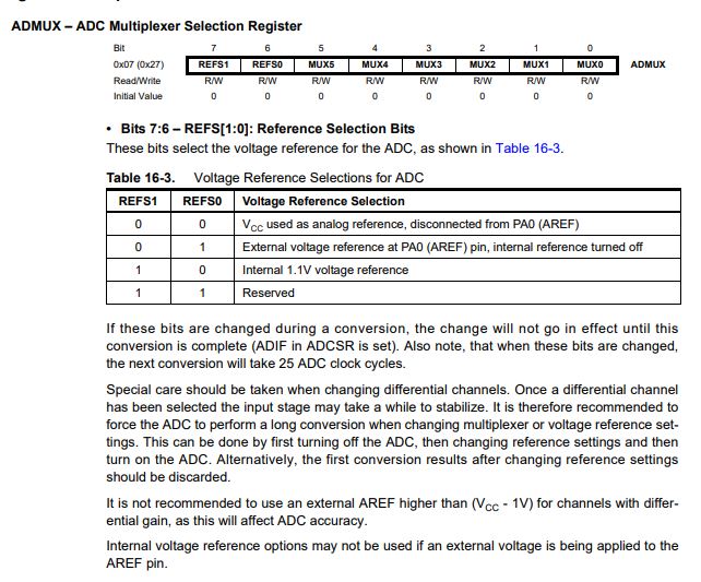
To use the ADC we have to configure 2 registers:
ADMUX ADC Multiplexer Selection Register (10 bit register)
REFS0 and REFS1 are used to select the reference voltage, the table below shows the available combinations.
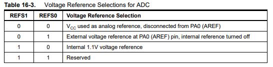
In my case i used the internal Vcc as my reference voltage.
MUX[5:0] - Analog Channel and Gain Selection Bits are used to select the pin we want to read the analog input and the gain.
After that i really got stuck and didn't understand what to do. There is no clear tutorial on the internet.
This code shows how I activate it in port PA0 , PA1 ,PA2 , PA3 and PA4
ADMUX = (0 << REFS1) | (0 << REFS0) // VCC ref
| (0 << MUX5) | (1 << MUX4) | (1 << MUX3) | (1 << MUX2) | (1 << MUX1) | (1 << MUX0); // ADC0 PA0
ADCSRA = (1 << ADEN) // enable
| (1 << ADPS2) | (1 << ADPS1) | (1 << ADPS0); // prescaler /128
2- Programming the MicroController Using the Arduino Coding Language
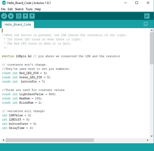
The first coding language I used to write the code is Arduino, as I am very used to it and it is very user friendly. However, there are some points that we should take into consideration. The first thing i should take into consideration is my PCB design, mainly all the components available in my circuit, and how they are connected to the Microcontroller.
In my circuit, i had many components:
- 1 x 20 MHz Crystal
- 2 x 22pF Capacitor
- 3 x 10 Kohm Resistor
- 2 x 499 ohm Resistor
- 1 x Red LED
- 1 x Green LED
- 1 x LDR
- 1 x 4-pin push button
In addition, in order to write my code using Arduino, I had to take into consideration the following important points:
- Pin mapping between Arduino IDE and Physical pinout diagram for the ATtiny44
- The Arduino Commands that are supported by the ATtiny44 microcontroller.
You can download the code for My Hello Board from the following links My Hello Board Code
Step 1 - Pin Mapping and Choosing Pin Modes
The first step when writing any code that controls a microcntroller is to set the pins that we are using as inputs and outputs. To do so we have to know how to refer to those pins in our code.
When writing a code for an Arduino UNO board, we always refer first to the inputs and outputs in the setup using the following commands:
- "pinMode(pin#, INPUT)" for an Input
- "pinMode(pin#, OUTPUT)" for an Output
Step 2 - The Arduino Commands
So the ATtiny44 does not have all the capabilities of an Arduino Board, thus not Commands in the Arduino code work. Thus we need to understand our limitations in order know how to write our code accordingly.
The following Arduino commands should be supported:
- pinMode()
- digitalWrite()
- digitalRead()
- analogWrite()
- shiftOut()
- pulseIn()
- millis()
- micros()
- delay()
- delayMicroseconds()
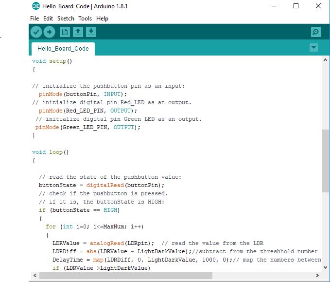
Step 3 - Writing the Code
In order to measure the light intensity using the LDR and cotrolling the LEDs, we need to right a code that does that exaclty.
So my code mainly measures the light intensity using an Analog Input. The measured value will then be compared with the light/dark threshhold set by me in the code, and based on that the delay time is calculated to control the frequency of the LEDs flashing. If there is light, meaning that the LDR value is high, the Green LED will blink at a frequency depending on the strength of light. On the other hand, if there is darkness, meaning that the LDR value is low, the Red LED will blink at a frequency depending on how dark it is.
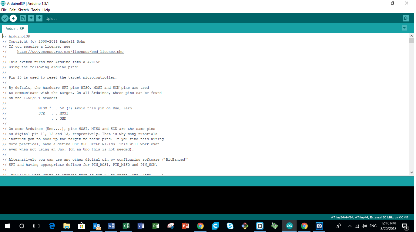
Step 4 - Uploading the AdruinoISP code to the Arduino Board
After finalizing the code, the next step is to upload the code to the newly constructed Hello Board. To do that, we have to set first the Arduino Board as an ISP. To do so, the following steps are followed.
- Choose the Board as "Arduino/Genuino Uno" by going to "tools" > "board" > "Arduino/Genuino Uno"
- Next choose the port where the Arduino is connected
- Then follow the following "file" > "exaples" > "ArduinoISP" to open the Arduino ISP code
- Next upload the code to the Arduino Board
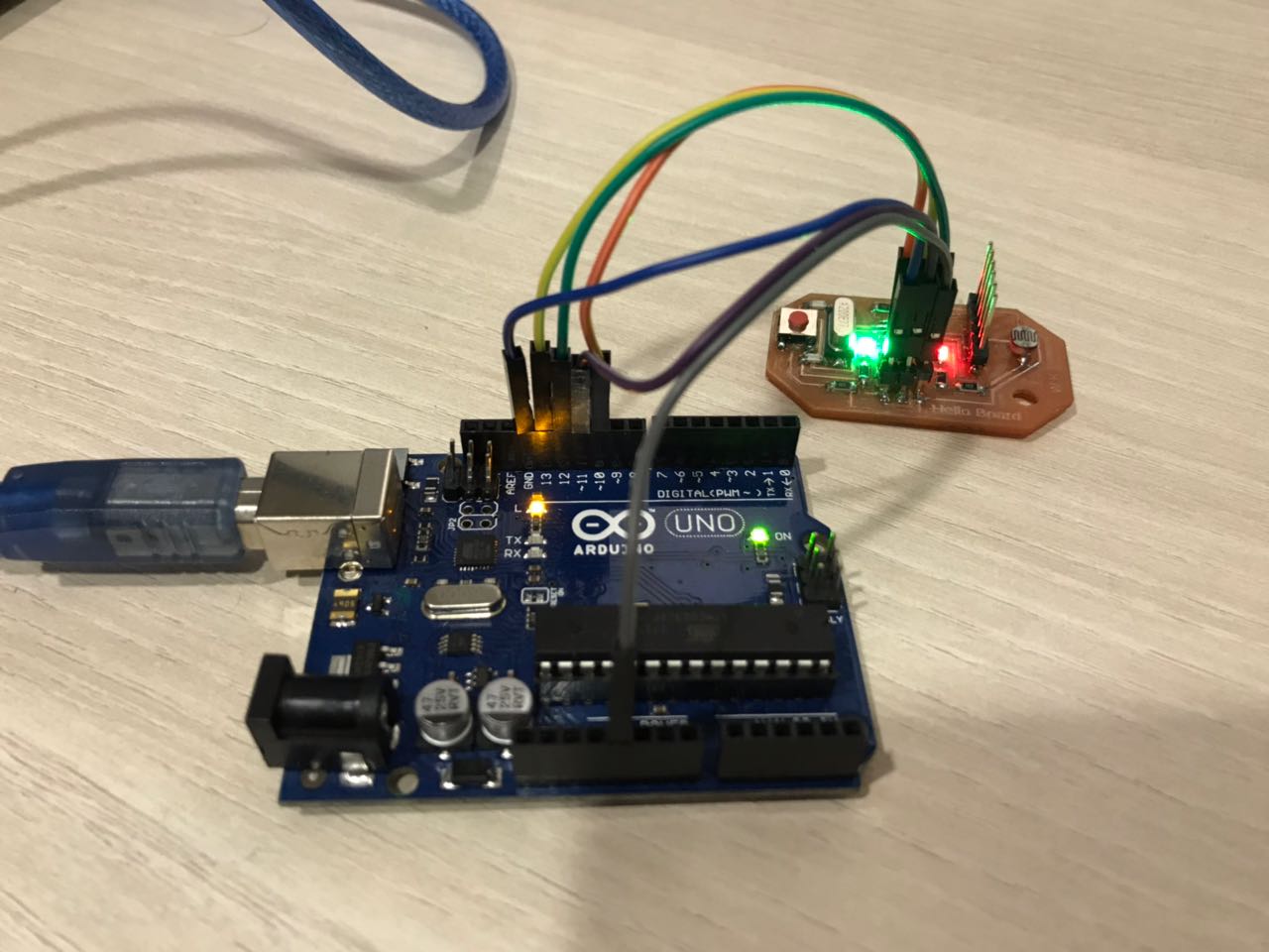
Step 5 - Uploading the code to the Hello Board using Arduino
After setting the Arduino board as an ISP, the next step is to push the code to the Hello BoardConnect the Arduino Board to the new Hello Board following those connections:
- Arduino 5V to Vcc
- Arduino GND to GND
- Arduino Pin 10 to Reset
- Arduino Pin 11 to MOSI
- Arduino Pin 12 to MISO
- Arduino Pin 13 to SCK
- Choose the Attiny44 board by pressing "tools" > "board" > "ATtiny24/44/84"
- Choose the Processor by pressing "tools" > "Processor" > "ATtiny44"
- Choose the Clock by pressing "tools" > "Clock" > "External 20 MHz"
- Burn Bootloader by pressing "tools" > "Burn Bootloader"
- Upload the code following "Sketch" > "Upload Using Programmer"
3- Programming the MicroController Using the C Coding Language
After trying to write the program that will control my Hello Board, in Arduino, the next step was to learn another programming language that i can use.
I chose to use C language, because there are many libraries and open-source code that are available online. In addition to that, i wanted to try and upload the C-code using my previously produced FabISP as the programmer and Linux-UBUNTU as an operating sytem.
You can download the code for My Hello Board from the following links
Step 1 - Choosing a Port Using C Code
The first step when writing any code that controls a microcntroller is to set the pins that we are using as inputs and outputs. To do so we have to know how to refer to those pins in our code.
For using a port I should write in the code the name of the register I will use then I activate the port then choose it as out put or input.
For example this is the code syntax to put PA5 as output
DDRA |= (1 << PA5);
// set pa5 as output in DDRA
This code is to show how to put PB2 as input and activate the pull up resistor related to it.
``` DDRB &= ~(1 << PB2); // set PB2 as input in DDRB
PORTB = 0b00000100; // SET PULL UP RESISTOR IN PB3 ```
Now I have learned the first part in micro-controller which is how to choose the port and use it as input or output.
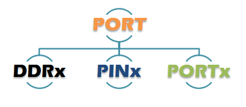
Step 2 - The C Commands
All the I/O pins of the ATtiny44 have multiple functions ( you can see them in the image above ) and they are “grouped” into ports.
Specifically the tiny44 have PORT A and PORT B each port have 3 registers: DDR, PORT and PIN. They are 8 bit registers ( attiny44 is 8bit architecture ) and each bit correspond to a pin of the attiny.
- DDR is read/write type and handle the direction of the pin ( 0 mean input , 1 mean output ).
- PORT is read/write type:
- If the DDR of the pin is an Output, writing 1 to PORT sets the pin HIGH and writing 0 sets the pin LOW. Reading the DDR returns the state of the pin.
- If the DDR of the pin is an Input PORT turn on or off ( 1/0 ) internal pull-ups resistors. Reading the DDR tell whether the pull-ups are on or off.
- PIN is read only, it’s used to read the input value of the pin.
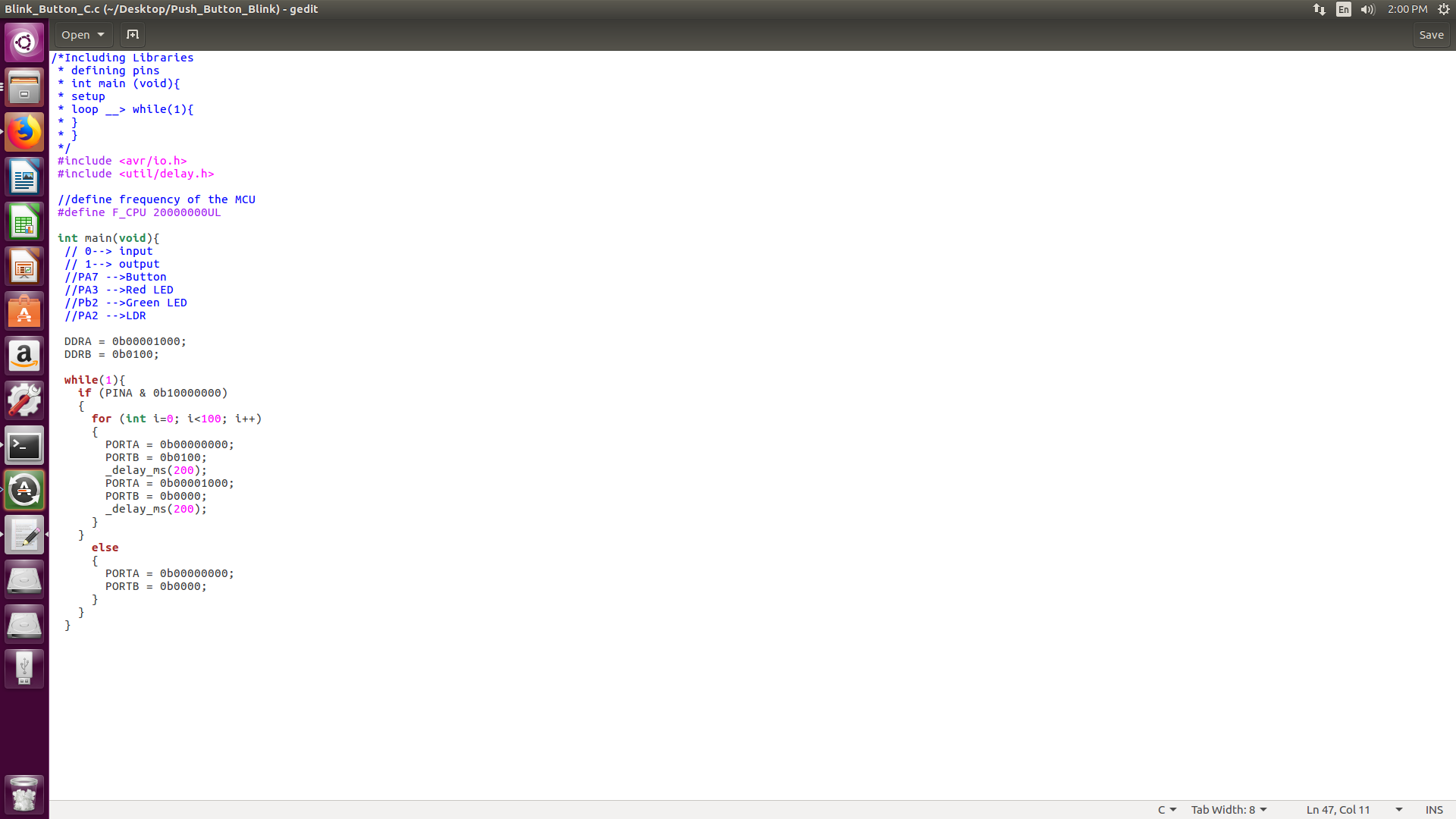
Step 3 - Writing the C Code
In this code, i wanted to press a button, and when it is pressed, i want the LEDs to flash, independent of each other.
So my code mainly checks if the Push Button is pressed. If it is pressed, the LEDs will flash one after the other. Else, nothing will happen.
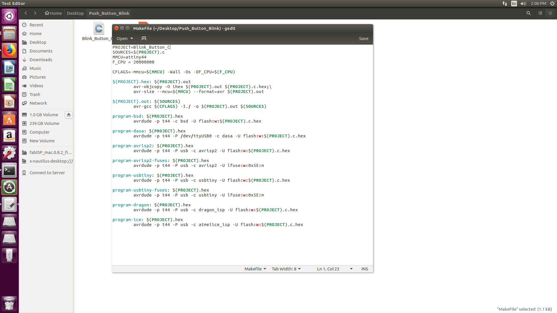
Step 4 - Preparing the Make File
The next step is to prepare the make file, that will be used to compile the c-code before pushing the code to the microcontroller.
In my case, i used the make file posted in the Archives on the following Link
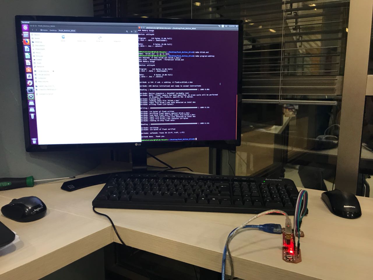
Step 5 - Uploading the C code to the Hello Board
After preparing the C-code for my Hello Board, the next step is to upload the code to the board.
To do so, I used a computer having a Linux - UBUNTU operating system, and my previously produced FabISP as my programmer.
The following steps are followed to upload the C code to the Hello Board
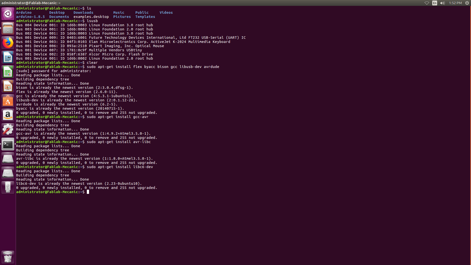
- Installing the AVR Libraries
- sudo apt-get install flex byacc bison gcc libusb-dev avrdude
- sudo apt-get install gcc-avr
- sudo apt-get install avr-libc
- sudo apt-get install libc6-dev
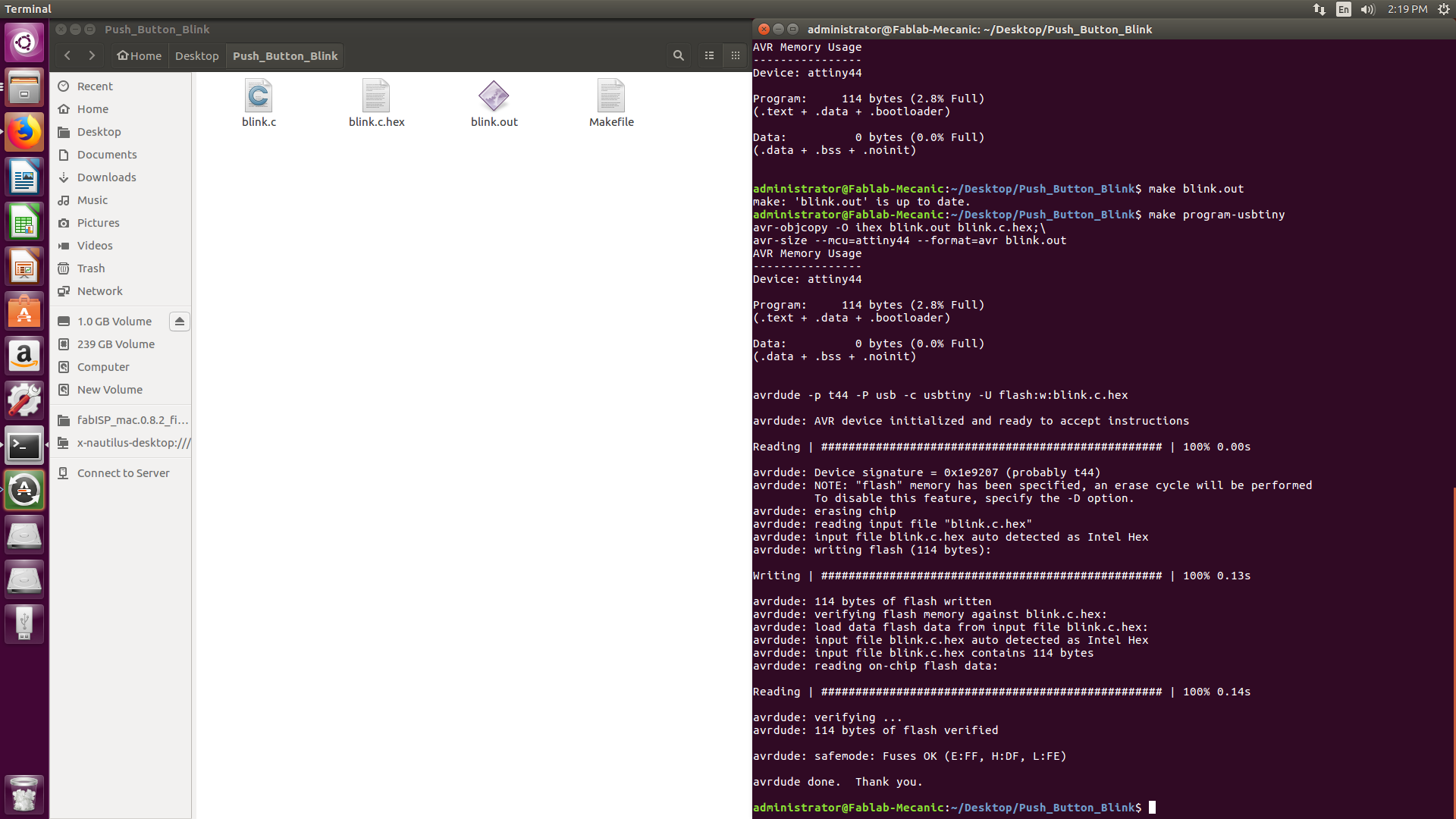
- Make HEX file
- make blink.hex
- Make Out file
- make blink.out
- Make program
- make program-usbtiny
You can download the code for My Hello Board with the Make File and HEX file from the following links Button and Blink C-code