Discovering Input Devices
There are many input devices in the market that could be used to gather data and connect the electronics system to the outside world. Those input devices could be a switch, distance sensors (Ultrasonic or Infrared), magnetic sensors, temperature sensor, light sensor, accelerometers and gyro sensors, sound sensors (microphones), vibration sensors, cameras and much more. Technically everything you see in all the equipment and machines you use in your daily life, like the iphone.
In this section, we will learn on how to use and connect a sensor to a microcontroller, and how to use it to collect data from its surrounding.
Assignment
We had a Group Assignment and an Individual Assignment this week.- Group Assignment Measure the analog levels and digital signals in an input device.
- Individual Assignment The individual assignment was mainly to measure something: add a sensor to a microcontroller board that we have designed and read it.
- Roland MDX-40 is the Desktop CNC machine used to mill copper boards.
- Tektonix TBS 1052B is the oscilloscope used to observe the operation of the microcontroller circuit board.
- National Instruments VirtualBench was used as a digital oscilloscope to observe and document the operation of the microcontroller circuit board.
- FLUKE 179 was the multimeter used throughout all the process.
- ProsKit SS 207 was the soldering iron used for welding the components.
- Eagle was used to design the PCB.
- GIMP was used to extract and enhance the image of the PCB design.
- Fab Module was the main online platform used to produce the g-code used by the CNC machine.
- Arduino IDE was used to write the code and upload the code.
You can check the Group Assignment on the following link: Group Assignment
Machines Used
The main machines and equipment used in this week's assignment are machines that are usually used to produce any PCB. The list of machines we used are the following:Software Used
The following software were used in this week's assignment:1- Group Assignment - Measuring the Analog Levels and Digital Signals in an input device
So our idea was to compare two sensors that would achieve the same job, or solve the same problem. One of them is Digital and the other is Analog.
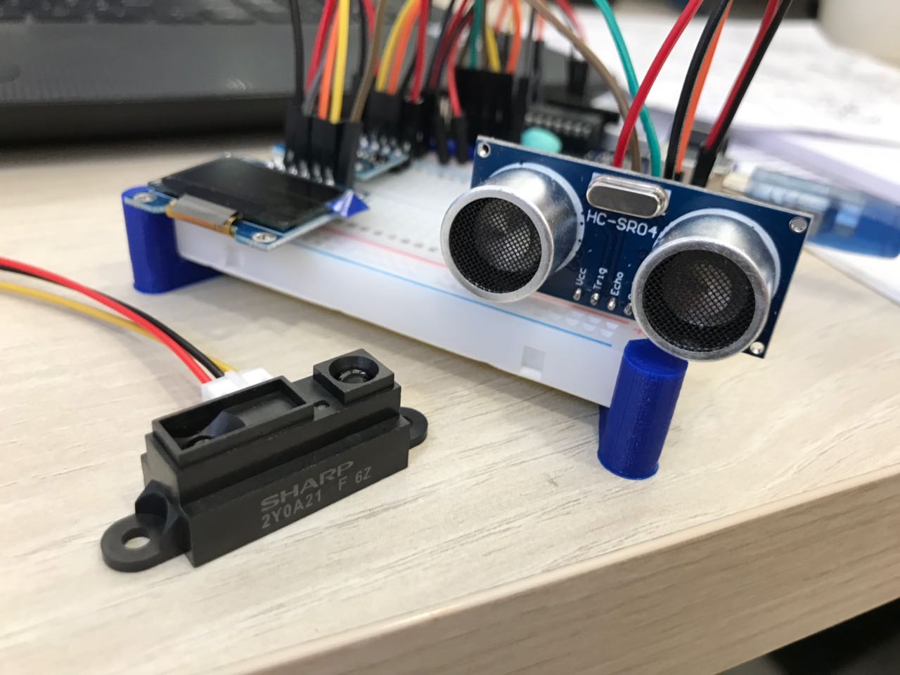
We choose to use two sensors that measure:
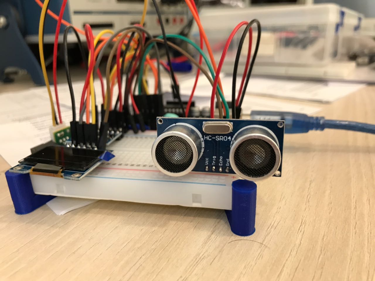
- The UltraSonic Sensor (HC-SR04): Digital Sensor
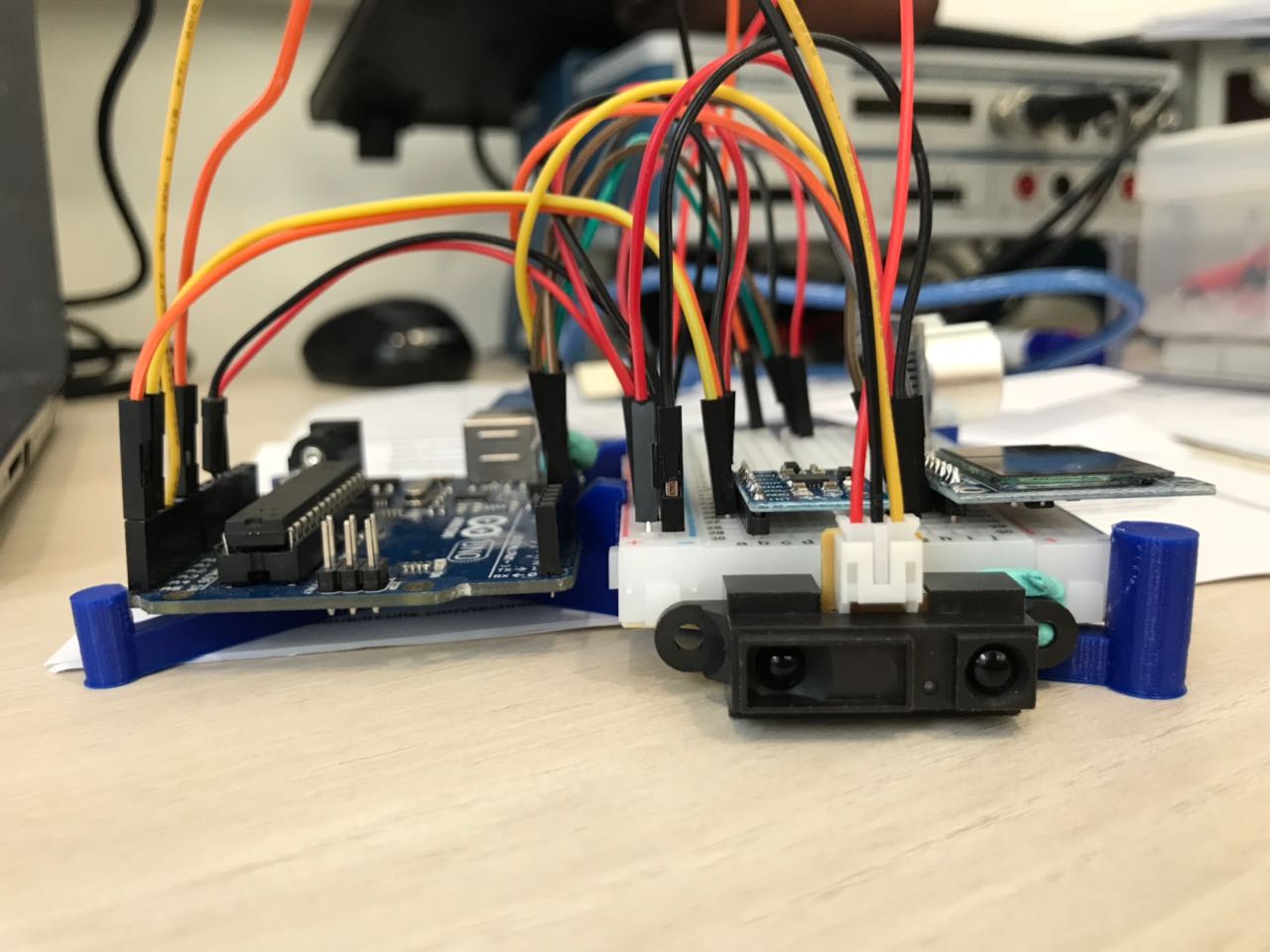
- The Infrared Sensor (SHARP 2Y0A21): Analog Sensor
Test 1 - Testing the Ultrasonic Sensor
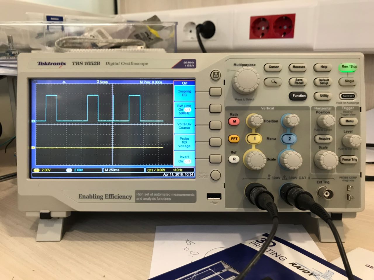
So the Ultrasonic Sensor is considered to be a Digital sensor because the microcontroller reads a digital signal from it. How the Ultrasonic mainly works by emiting an ultrasound at 40 000 Hz which travels through the air and if there is an object or obstacle on its path It will bounce back to the module. Considering the travel time and the speed of the sound you can calculate the distance.
The HC-SR04 Ultrasonic Module has 4 pins, Ground, VCC, Trig and Echo. The Ground and the VCC pins of the module needs to be connected to the Ground and the 5 volts pins on the Arduino Board respectively and the trig and echo pins to any Digital I/O pin on the Arduino Board.
In order to generate the ultrasound you need to set the Trig on a High State for 10 µs. That will send out an 8 cycle sonic burst which will travel at the speed sound and it will be received in the Echo pin. The Echo pin will output the time in microseconds the sound wave traveled.
Test 2 - Testing IR Distance Sensor
The distance sensor produced by Sharp is a popular and relatively low cost solution for measuring distance.
In this test we will use the 2YOA21 model and the characteristics of this sensor are:
- Minimum Measuring Distance = 10cm;
- Maximum Measuring Distance = 80cm;
- Infrared Proximity Sensor;
- Analog output inversely proportional to distance;
- Sensor is Ratiometric;
- Operating Supply Voltage = 4.5V to 5.5V;
- Average Supply Current – Typical = 30mA;
- Response Time = 38 ± 10ms.
Comparing Both Results
Concerning the Ultrasonic Distance Measuring sensor, you can easily read the information from it on the Serial Monitor, as the signal recieved from it is a digital signal, which is converted directly by the help of the existing libraries into the measurments and numbers we need.
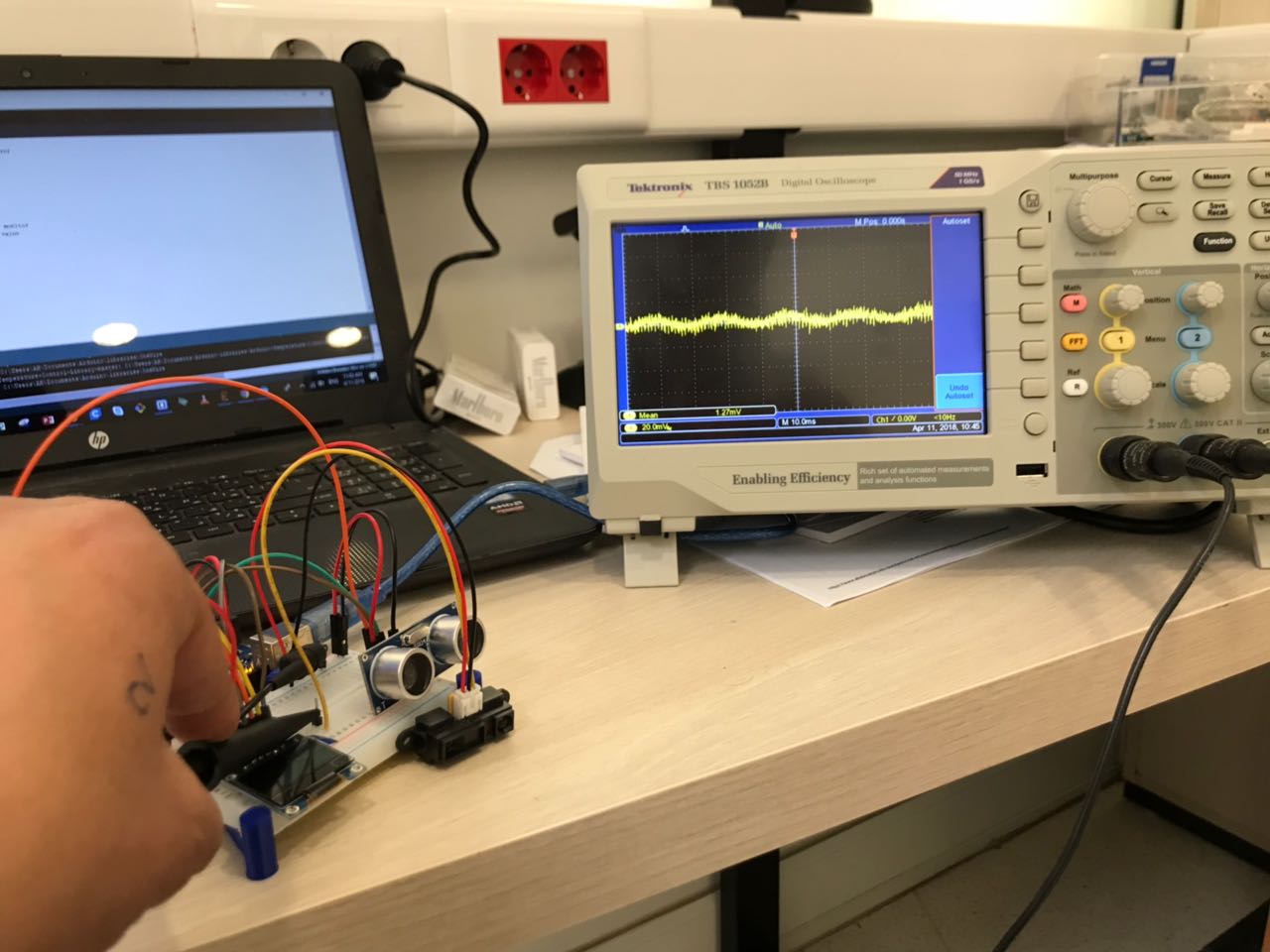
However, on the other hand, with the InfraRed Sharp Distance sensor, it's a bit harder to get data from it, casue you need to calibrate it first. The IR sensor sends analog data to the Arduino Board, which is technically a variation is the voltage. Thus what you can read on the serial monitor is a variation in voltage. To convert that into readable information, we should check the values we read with respect to various set distances and calibrate accordingly.
The video represents how the signal is sent and recieved from and back to the arduino board. The signal recieved at the ECHO signal by the arduino board is a digital signal that represents the variation in distance.
On the other hand,the picture represents how the signal is received from the IR sensor.It is mainly a voltage level that variates according to the distance.
2- Individual Assignment - Measure Something
In the individual assignment, we had to measure something using a board we have designed.
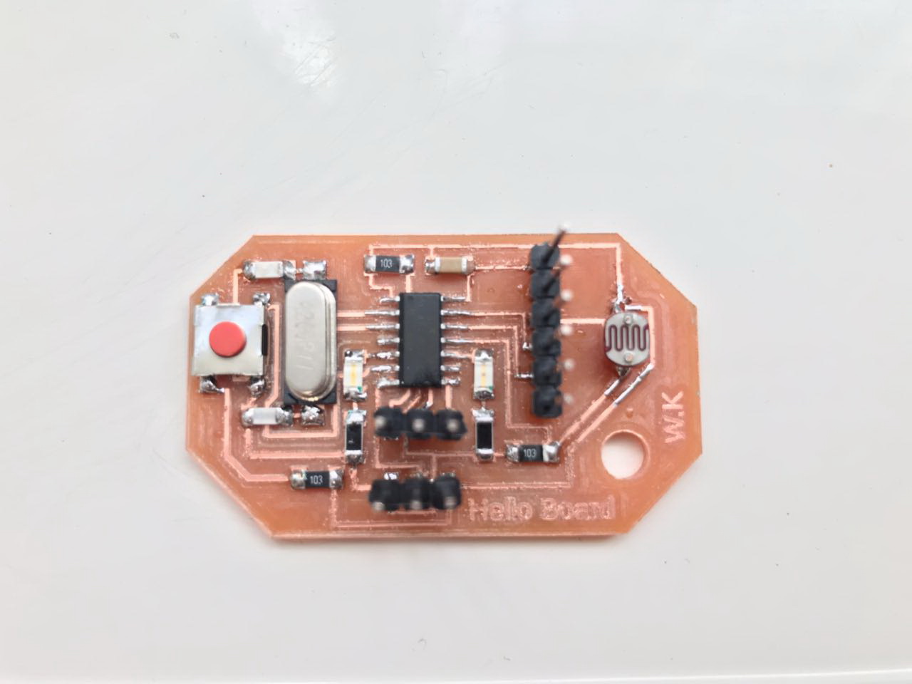
So as a first step, i already built my Hello Board in the past weeks having a built in LDR sensor on it. The board has 2 LEDs of different colors, one Red and one Green, in addition to a Photoresistor (LDR) and a Button. The objective of the board is to measure the light intensity and based on that, the LEDs will turn on. The Green LED will turn ON when there is light and the Red LED will turn on when there is darkness. Note that the frequency of the LEDs flash depends on the intensity of Light or Darkness measured by the LDR. The more the light or darkness, the faster the blink of the LED.
You can check the full details of the Hello Board by visiting the following link My Hello Board
Reading Data from the Sensor
So unfortunately, the Attiny44 chip does not have the capability to connect to the Serial Moniter in the Arduino IDE other than using the software serial, which will occupy more digital inputs and outputs.
So i chose the threshhold point based on trial and error, by observing the different LED blinking when changing the threshhold point in the software. Thus after dowloading the final code to the new Hello Board, I wanted to test it and check its full capabilities.
Due to my limitation, i chose to represent the values read was by using the on board LEDs. Thus the board reads an Analog Value from the LDR, and converts it into a frequency for th LEDs blinks.
So i gave the board an extenal power using an FTDI Basic Breakout - 5V and checked if it works all by itself. And it did work :D. The video represents the functionality of My Hello Board.
3- Individual Assignment - Building My New PCB
As a second step in this week's individual assignment, I wanted to start designing a new board that will be used on board of the Pipe Surveying Robot i am planning to build in my Final Project.
Thus to do that, some research was done to check the available sensors that would achieve the requirements i need in my system. The main mission of my Robot is to survey existing pipes, gather data related to its path underground, mainly anglural data, and save this data on a memory stick.
So the set of sensors (Inputs) that i could be using on my robot are mainly the following:
- Ultrasonic Sensor used to measure distance
- Infrared Sensor used to measure distance
- Accelerometer and Gyroscope used to measure angular acceleration and the angular position
- Stepper Motor Drivers used to control the steppr motors that will be installed on my robot.
- MicroSd Module used to save data on an external data memory card.
The next step after chosing the inputs i want to use is to test those sensors. I did my testing using Arduino Uno, because i am planning to use the ATmega328/p as the main microcontroller on my board, which is the same microcontroller used on the Arduino, thus both boards will have almost the same capabilities and limitation.
1 - Ultrasonic Distance Sensor
As mentioned above, the Ultrasonic Distance Sensor is a Digital Sensor. The HC-SR04 Ultrasonic Sensor Module has four pins:
- Vcc which is connected to the 5V power source, either from the Arduino Board, or any other board
- Trigger pin which is connected to a digital pin which will be set as an output pin
- ECHO pin which is connected to a digital pin that is set to be an Input
- GND which is connected to the GND of the power source or board you are using
You can download the data sheet for the Ultrasonic Ranging Module HC-SR04 from the following
2 - InfraRed Distance Sensor
The IR sensor is an Analog sensor. The SHARP IR Distance sensor is connected to the control board using 3 pins:
- Vcc which is connected to the 5V power supply from the board
- GND which is connected to the GND pin on the control board
- Vo pin which is the output pin that is connected to an Analog Input pin to the microcontroller
You can download the data sheet for the SHARP IR Distance Measuring Sensor Unit from the following
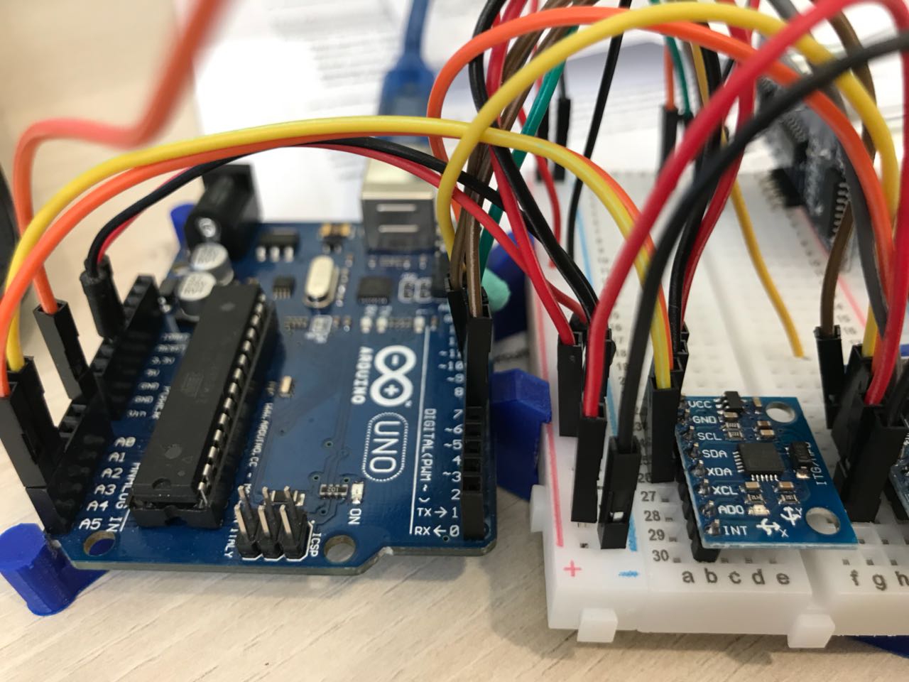
3 - Accelerometer and Gyro (MPU-6050)
The main sesnor i will be using in my Pipe Surveying Robot is the the MPU-6050.
The InvenSense MPU-6050 sensor contains a MEMS accelerometer and a MEMS gyro in a single chip. It is very accurate, as it contains 16-bits analog to digital conversion hardware for each channel. Therefor it captures the x, y, and z channel at the same time. The sensor uses the I2C-bus to interface with the Arduino.
The MPU-6050 is not expensive, especially given the fact that it combines both an accelerometer and a gyro. Also note that Invensense has combined the MPU-6050 with a magnetometer (compass) in a single chip called MPU-9150.
The accelerometer measures the acceleration along one direction, while the gyroscope measures the angular acceleration on one axis. The module has 8 pins:
- Vcc that could be connected to a 5V or 3.3V power suply. The MPU-6050 module has a voltage regulator on board
- GNG pin which is connected to the GND of the control board
- SCL which has to be connected to SCL pin of the micro controller, known by the Analog 5 pin on the Arduino Board
- SDA pin which has to be connected to the SDA pin of the microcontroller, known by the ANalog 4 pin on the Arduino board.
- XDA pin
- SCL pin
- AD0 pin
- INT pin
Open the Serial Monitor, move the sensor and try to see how the values change. Below is the code used to read data from the MPU-6050
You can download the data sheet for the Accelerometer and Gyro (MPU-6050) from the following
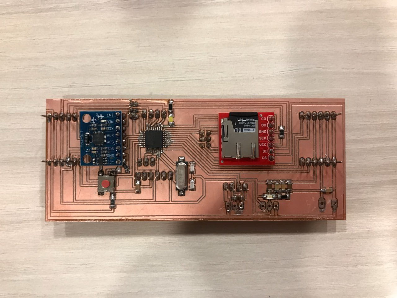
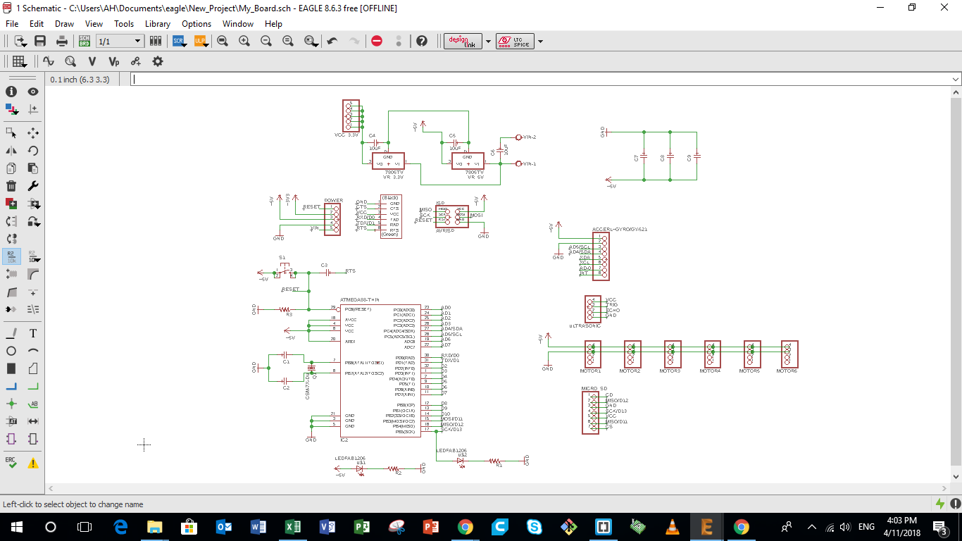
4 - Preparing the Board Design
Next i need to design the control board of my pipe surveying robot i am building. Many points had to be taken into consideration while designing the board, mainly the Architecture of the Microcontroller i am using, the pin connection to the sensors and outputs i am using. The different parts of the Control board are described in details below.
The image represents the different part of the full control board such as:
- Microcontroller
- Power and Input Pins
- Inputs and Output Pins
- Power Board
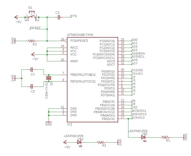
4 a - Microcontroller Connections
In my first prototype of my board, i will be using the ATmega328/P, which is the same Microcontroller used on the Arduino UNO board.
Saying that, and based on the data sheet, other than the Analog and Digital pins, the following connections were made:
- RESET connections. The Reset pin on the microcontroller will be connected to the Reset Pin of the ISP, and that of the FTDI, plus to a push button to be able to Reset the microcontroller whenever i want.
- XTAL1 and XTAL2 pins that will be connected to the external clock, in our case a Crystal having a frequency of 16000 mhz
- Debugging LED, that is connected to the SCK (Arduino pin13) which is mainly used for debuggining
- Power LED, that is connected in parallel to the input 5V Vcc.
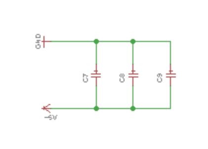
- Decoupling Capacitors, that are connected in paraller to the +5V input, to regulate the voltage and current recieved by the microcontroller, and achieve a stable power supply. More details on how to calculate the Decoupling capacitors can be found on this link
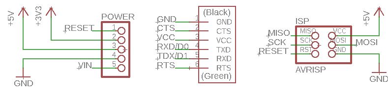
4 b - Power and Input Pins
The main Input Pin headers that i will be using for my board are mainly the following:
- Power Pins that will have a Reset Pin, a 3.3V and 5V power source, a GND pin and a Vin pin.
- FTDI pins that are used to connect the board to the computer using an FTDI cable
- ISP pins that will be used to connect the board to the programmer while programming it.
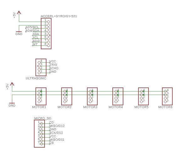
4 c - Inputs and Outputs Pins
A set of pin headers was prepared for the Inputs and Outputs that will be used in my system and connected tot he Microcontroller i am using.
Each pin head will have a Vcc pin and a GND pin, plus 1 or 2 dedicated Analog or Digital pins.
- Inputs
- Distance Sensor:I will be using either the Ultrasonic Sensor or the IR sensor. But i need to test both in various settings to decide which better achieves the wanted job. However due to the limitations in the number of pins on my board, one set of pin header was prepared to the distance sensors, that could be used for both the Ultrasonic Sensor or the IR sensor. The pins chosen on the micro-controller are Analog Pins that could be also used as digital inputs or outputs.
- Gyro and Accelerometer: The Accerlometer has 8 pins. So i will prepare a pin header that has pins, that will be mainly used to support the sensor flat paraller to the board. However, only Four pins will be connected to the microcontroller, the VCC and GND plus the SCL and SDA pins on the microcontroller.
- Outputs Outputs pins will mainly control the Motors that move the robot and the MICRO SD card module. More details will be mentioned in the Outputs Week.
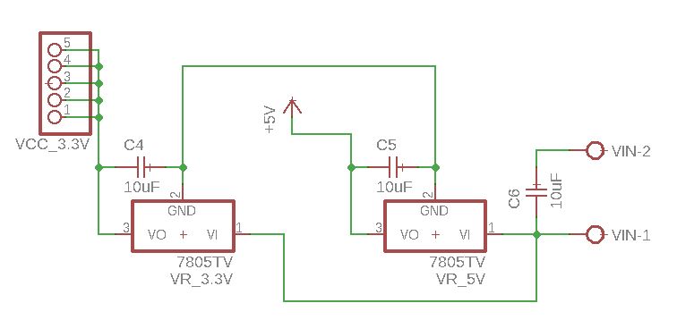
4 d - Power Board
My board will have one battery as a power source dew to the limtied and tight space. Thus i will need power regulators that will achieve having a 12V, 5 V and 3.3 V power supplies on the board. Saying that a power regulation circuit was added to the board to achieved that.
5- Production and Testing of My Board
Due to the time limitations (Easter Break), both the Inputs and Outputs week assignments were grouped in one. So the final design of the Board and its production was done in the Outputs Assignment of next week.
In the Outputs Week, i finalized the design of the board, produced it, and tested both Inputs and Outputs.
All details could be found on the following link