Discovering Output Devices
There are many output devices in the market that could be used to connect the microcontroller to the outside world. Those output devices could be an LED, a voltage relay,an LCD, a Stepper or Servo motor and many more. Technically everything that allows you to know what is happening inside the circuit or what provides motion to a system.
In this section, we will learn on how to use and connect an output device to a microcontroller, and how to use it to produce motion and save data that is collected using sensors from its surrounding.
Assignment
We had a Group Assignment and an Individual Assignment this week.- Group Assignment Measure the power consumption of an output device.
- Individual Assignment The individual assignment was mainly to add an output device to a microcontroller board I've designed, and program it to do something.
- Roland MDX-40 is the Desktop CNC machine used to mill copper boards.
- Tektonix TBS 1052B is the oscilloscope used to observe the operation of the microcontroller circuit board.
- FLUKE 179 was the multimeter used throughout all the process.
- ProsKit SS 207 was the soldering iron used for welding the components.
- Eagle was used to design the PCB.
- GIMP was used to extract and enhance the image of the PCB design.
- Fab Module was the main online platform used to produce the g-code used by the CNC machine.
- Arduino IDE was used to write the code and upload the code.
You can check the Group Assignment on the following link: Group Assignment
Machines Used
The main machines and equipment used in this week's assignment are machines that are usually used to produce any PCB. The list of machines we used are the following:Software Used
The following software were used in this week's assignment:1- Group Assignment - Measuring the power consumption of an output device
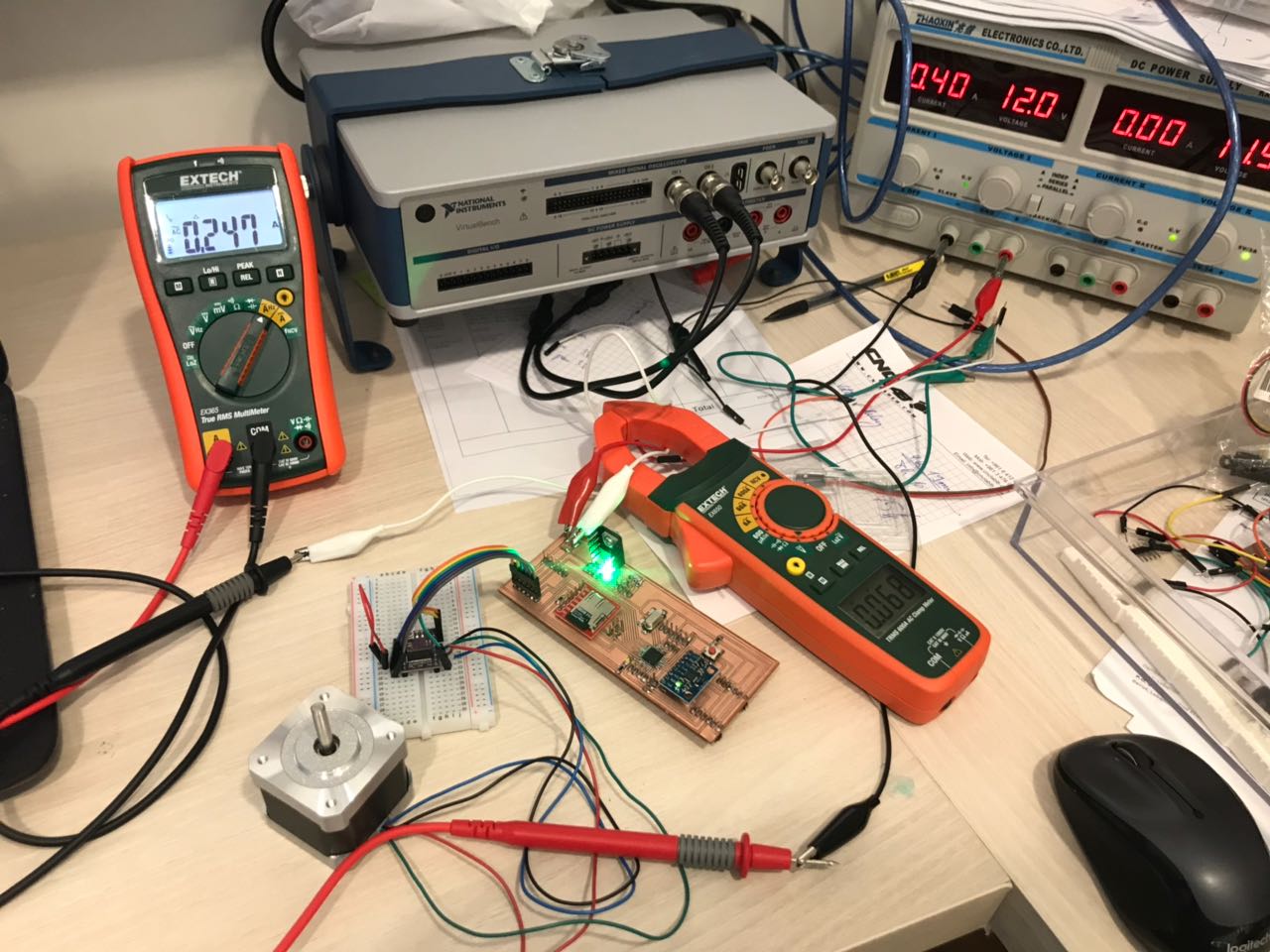
So what i did was connect a multimeter to measure the power consumption the stepper motor is consuming while in motion.
Testing the Power Consumtion of a Stepper Motor
The stepper motor was set on contineous motion, and the power consumption was measure. The power consumption was equal: 0.247A
2- Individual Assignment - Measure Something
In the individual assignment, we had to output something using a board we have designed.
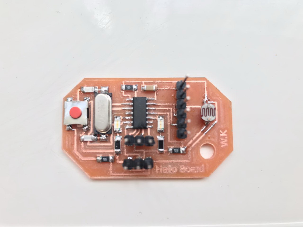
So as a first step, i already built my Hello Board in the past weeks having a built in LDR sensor on it. The board has 2 LEDs of different colors, one Red and one Green, in addition to a Photoresistor (LDR) and a Button.
In this example, the LED is considered to be the output device.
You can check the full details of the Hello Board by visiting the following link My Hello Board
Controlling an Output Device
The objective of the board is to measure the light intensity and based on that, the LEDs will turn on. The Green LED will turn ON when there is light and the Red LED will turn on when there is darkness. Note that the frequency of the LEDs flash depends on the intensity of Light or Darkness measured by the LDR. The more the light or darkness, the faster the blink of the LED.
Due to my limitation, the only way to represent the values read was by using the on board LEDs. Thus the board reads an Analog Value from the LDR, and converts it into a frequency for th LEDs blinks.
So i gave the board an extenal power using an FTDI Basic Breakout - 5V and checked if it works all by itself. And it did work :D. The video represents the functionality of My Hello Board.
3- Individual Assignment - Building My New PCB and Programming it
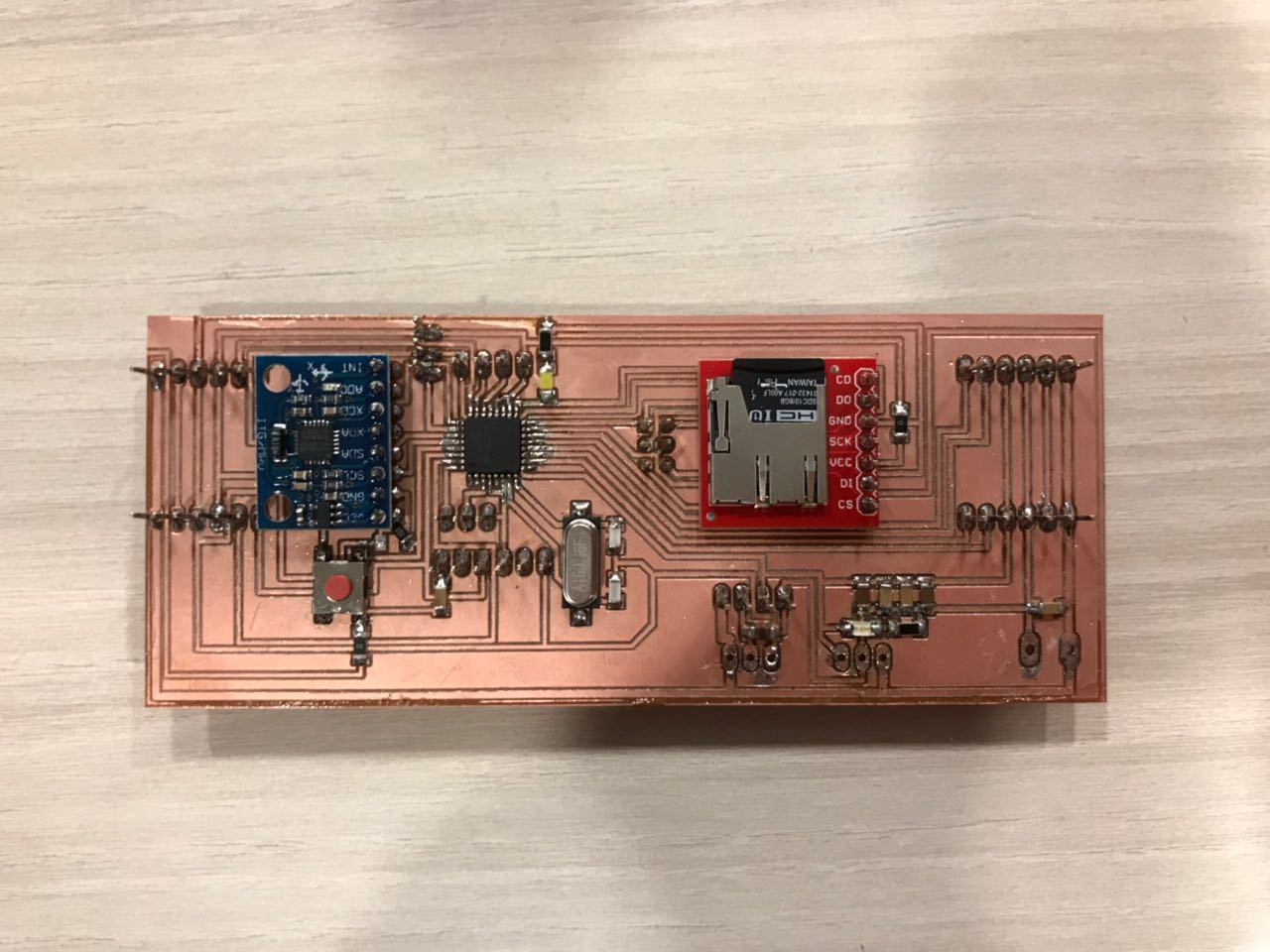
As a second step in this week's individual assignment, I wanted to start designing a new board that will be used on board of the Pipe Surveying Robot i am planning to build in my Final Project.
Thus to do that, some research was done to check the available outputs that i will be using to control the robot. The main mission of my Robot is to survey existing pipes, gather data related to its path underground, mainly anglural data, and save this data on a memory stick.
So the set of outputs needed that i could be using on my robot are mainly the following:
- Stepper Motors used to put the robot into controlled motion
- Servo Motor could be used to set the angles of the wheels with the pipe walls
- Micro SD module used to save the collected data to be studied later.
The next step after chosing the outputs i want to use is to test those outputs. I did my testing using Arduino Uno, because i am planning to use the ATmega328/p as the main microcontroller on my board, which is the same microcontroller used on the Arduino, thus both board will have almost the same capabilities and limitation.
1 - Preparing the Board Design
Next i need to design the control board of my pipe surveying robot i am building. Many points had to be taken into consideration while designing the board, mainly the Architecture of the Microcontroller i am using, the pin connection to the sensors and outputs i am using.
When i first designed my board, the idea was to have 6 wheels drived by 6 small stepper motors. However, because i could not find the stepper motors i want in the market, i decide to change my design to have 4 NEMA 17 stepper motors. Those motors will drive 4 Mecanum Wheels that will achieve front motion and linear motion when needed, to correct the angle of the robot inside the pipe.
In addition to that, a servo motor will be used to control the angle of contact between the wheels and the inner survace of the pipe. Another servo could be used to push to the top side of the pipe to prevent slipage while motion.

2 - Outputs Pins
Based on the new design, some edits were made on the board design, to achieve what i want. Two stepper motor output pins were deleted, and 2 Servo motor output pins were added.
- Stepper Motor:I will be using a DRV8825 Stepper Motor driver to control the Stepper motors in my system. So a 6-pin header was designed on the board that whould supply the motor driver with 12V power supply for the motors, a 5V power supply for the board, 2 GND pins, and 2 Digital Pins.
- Servo Motor: The Servo Motor needs 3 pins. So i will prepare a pin header that has 3 pins, one connect to 5V power supply.
- SparkFun microSD Transflash Breakout: The SparkFun microSD Transflash Breakout has 7 pins. So i will prepare a pin header that has 7pins, that will be mainly used to support the breakout flat paraller to the board. The 7 pins will be connected to the microcontroller as described above.
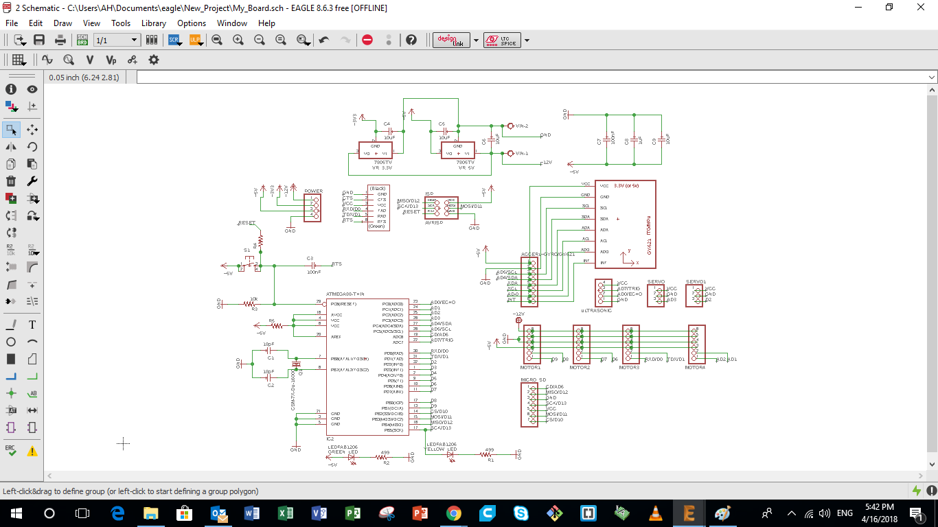
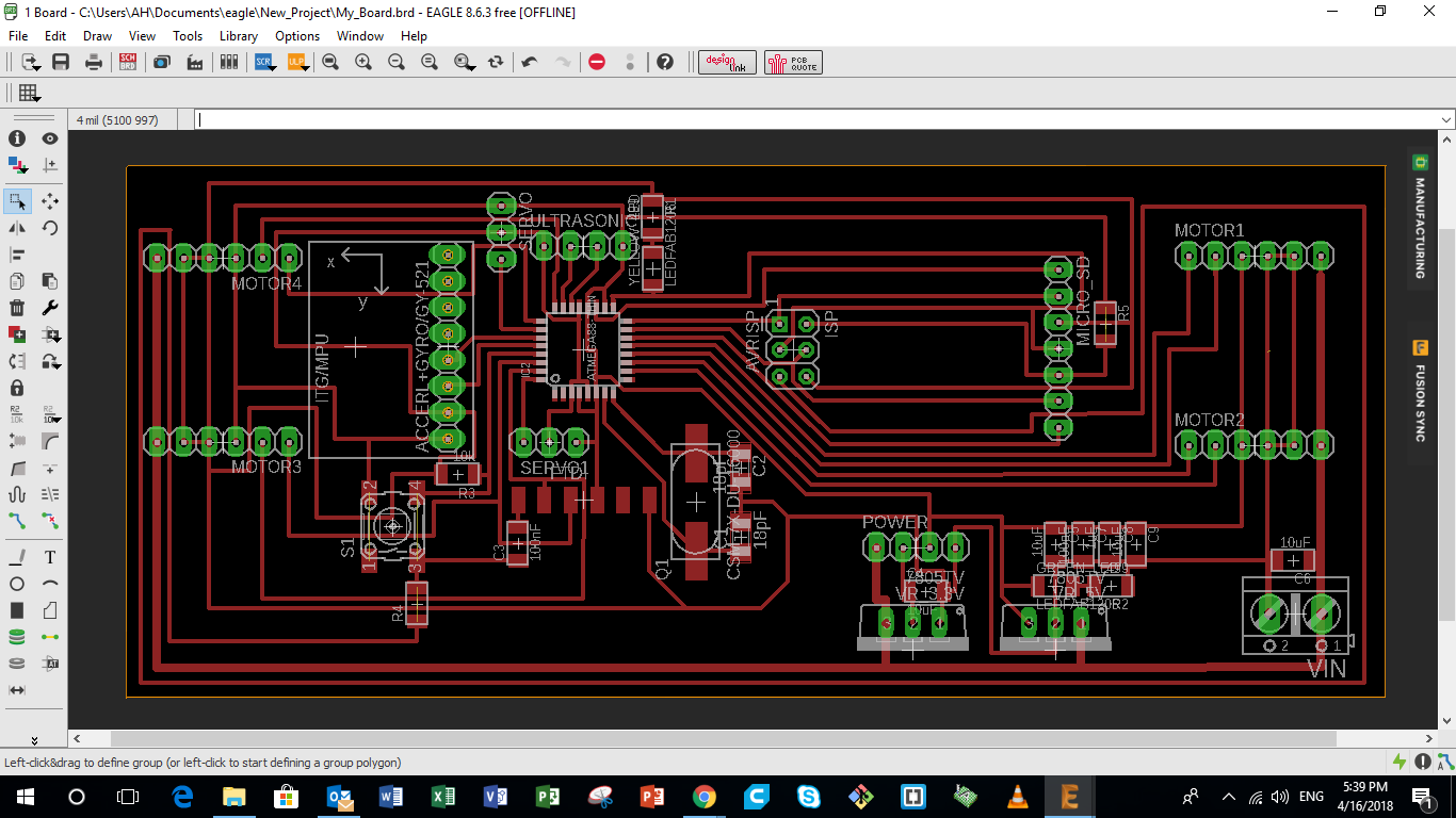
3 - Finalizing Board Design using Eagle
After connecting all the components on the board, the next step is to organize the schematic of the components. This schematic represents the location of the components on the board and the path of the connection in between the components. This step takes time and requires some art and concentration. During this level, the following points must be taken into consideration:
- The connecting lines have to be more than 12 in width
- Different connecting lines must not overlap, otherwise a short circuit will occur
You can download the original Eagle design from the following links: My Board
4 - Preparing Images Used for Machining Coper Board
After finalizing the layout of the PCB on Eagle, we want to extract the image that represents the PCB design. To do so we need to follow the following steps.
- First we turn off all layers by following the following path "view" > "layer settings" > "select none"
- Next we turn on only the layers we want to appear, mainly the ones we need to stay on the copper board during the milling process
- Extract the image in a monocrome form
So the next step after extracting the image from Eagle is to produce the images we need to use on Fab Modules to generate the g-code later.
So first we open the original image from Eagle and "extract as" a new copy that you can edit.
Using GIMP is easy, just fill the area you dont want with black and that's it. I produced 3 images to be used in fab modules. The images are the following:
- Internal Path represents the internal path of the PCB
- Drilling Positions represents the drilling positions of the PCB
- External Path represents the internal path of the PCB
You can download the extracted images for My Board from the following links:
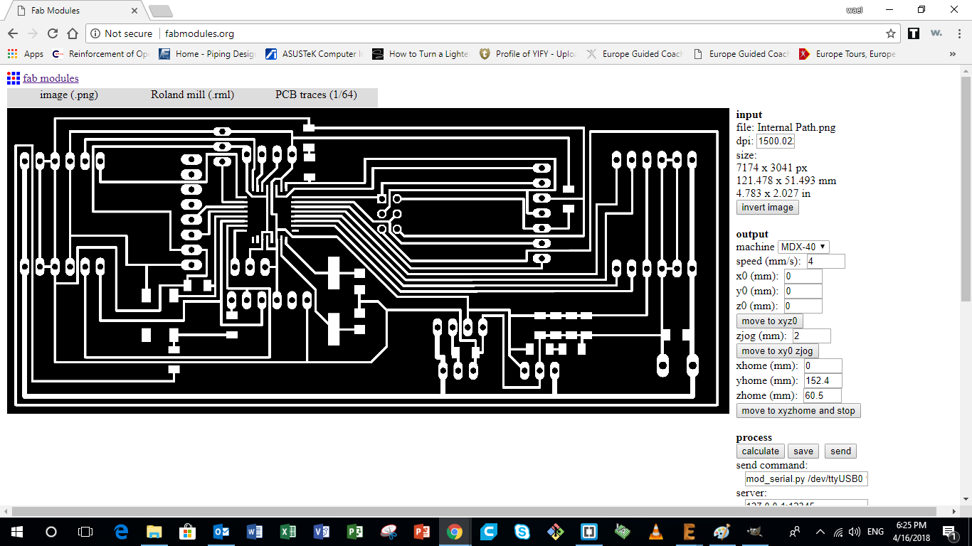
5 - Preparing G-Code using Fab Modules
After extracting all images that represent the internal and external paths of the milling bit, it's time now to produce the g-code. I used Fab Modules to produce the g-code for PCB milling on the Roland MDX-40.
The following steps were followed on Fab Modules to generate the g-code:
- Choose input format and select image (png) that the g-code is going to be generated from
- Then select the file from the specific folder
- Then go on to Output format and select the format that applies to the CNC machine you are using, in our case it was Roland mill (.rml)
- Then select Process and choose PCB traces (1/64) for internal paths and drilling and PCB Outline (1/32) for the external parameter
- Then under Output, select the CNC machine you are using, it was a Roland MDX-40. Change the X0, Y0 and Z0 to save space on copper board used. Then check the Feed Speed. I was using 4mm/sec for the Internal Traces and 0.5mm/sec to the External Parameter and Drilling
- Then Under Process, adjust the cut depth which should be 0.0 mm for the internal tracing, and 1.7mm for the external parameter and drilling. The tool diameter (milling bit) which was 0.1 mm for the internal traces, 1 mm for the external parameter, and 0.8 mm for drilling.
The Number of offsets used was 4. The offset overlap used was 70%
No other adjustments were be made. - Once the Input, Output, and Process tabs are double have been adjusted and double checked. Go ahead and press the Calculate button
- Then finally click the Save button and save it to the designated folder. It would be saved as an .rml file
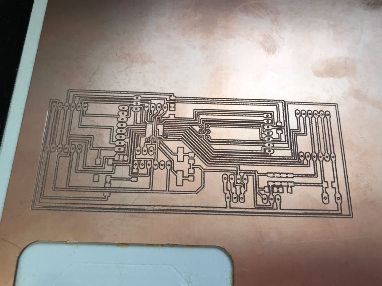
6 - Machining Copper Board
After preparing the G-code, the following steps were taken to mill the layout onto the copper board:
- First I needed a software that would send the g-code directly to the Roland MDX-40. In my case I used the Drop-Out software to send the .rml file to the CNC machine
- On the Drop-Out application press the add button and choose the .rml file you created and press open
- Then go to File and select Print Setup
- On the Print setup first choose the name of your printer, in my case it was the Roland TS-30
- Then go to Properties and press the Tool tab, the only thing that should be adjusted are the Z down position and Z engraving pitch both should be at 0.00 mm. During the milling the RPM used was 10,000 for all jobs
- Then go on to the Options tab and select Operation Panel
- Set the X and Y-axis on the position where you want your PCB to be engraved on the copper board inside the CNC, then press the XY axis SET button
- As for the Z-axis, we needed to zero the tool at the top surface of the copper board. In order to do this delicate process we need to gradually bring it down onto the board, with the help of a multimeter with the beep mode on and have one of the cables on the copper board and the other on the drilling bit. In this case as soon as the drill-bit touches the copper board the multimeter would beep. Make sure to go extremely slow at the end so you dont risk breaking your drill-bit
- Once the beep is heard, you know that the drilling bit is right at the surface and you can go back to the operational panel (on Drop-out), select the Z-axis from the dropdown menu and set the Z-axis.
- Once everything is set press OK until you reach the first page of drop-out and press theOutputbutton. Your CNC machine should now start the process of milling/engraving the copper plate set inside. watch the process until its done
- Check the final result, using a multimeter with the beep setting to make sure components are isolated and all conductivity channels are connected
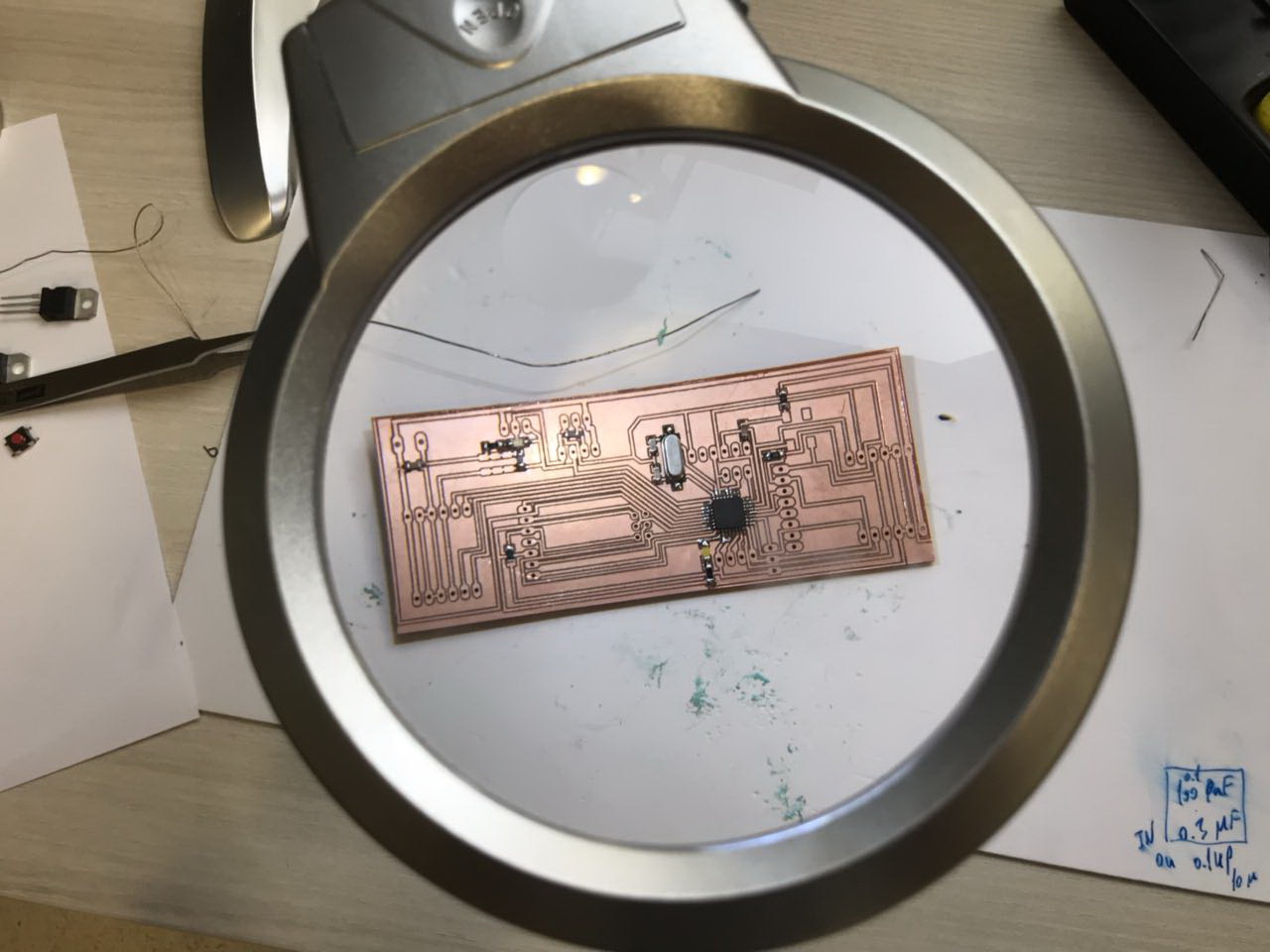
7 - Welding All Components
Now that we have the PCB layout cut-out, the next step is to start soldering. In order to do so we first need certain tools to proceed, find the list with specs below:
- Soldering Iron: set at 320 degrees celcius
- Solder wire: 0.5 mm
- Tweezers
- Desoldering copper
- Vacuum
- Tack-it
The following list represents the list of components used in My Board:
- ATmega328/P
- 1 x 16 MHz Crystal
- 2 x 22pF Capacitor
- 2 x 10uF Capacitor
- 1 x 1uF Capacitor
- 2 x 100pF Capacitor
- 3 x 10 Kohm Resistor
- 2 x 499 ohm Resistor
- 1 x White LED
- 1 x Green LED
- 1 x 4-pin push button
- 1 x 6-pin FTDI pin headers
- 1 x 6-pin ISP pin headers
- 4 x 6-pin headers
- 1 x 6-pin headers
- 2 x 3-pin headers
- 1 x 4-pin headers
Now for the final step in this process, make sure all connections are ok using the multimeter on the beep option. And you should be set to move on to the next step.
8 - Downloading Firmware
After finalizing the code, the next step is to upload the code to the newly constructed Board. To do that, we have to set first the Arduino Board as an ISP. To do so, the following steps are followed.
- Choose the Board as "Arduino/Genuino Uno" by going to "tools" > "board" > "Arduino/Genuino Uno"
- Next choose the port where the Arduino is connected
- Then follow the following "file" > "exaples" > "ArduinoISP" to open the Arduino ISP code
- Next upload the code to the Arduino Board
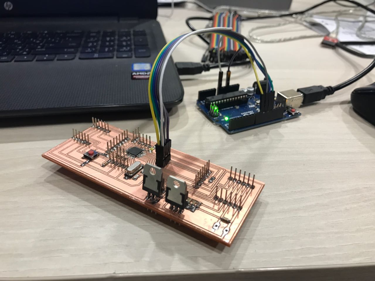
After setting the Arduino board as an ISP, the next step is to push the code to My Board
Connect the Arduino Board to the new Board following those connections:
- 5V to Vcc
- GND to GND
- 10 to Reset
- 11 to MOSI
- 12 to MISO
- 13 to SCK
- Choose the Arduino/Genuino UNO board
- Choose the terminal that the Arduino is connected to, usually a COM and a Number
- Burn Bootloader by pressing "tools" > "Burn Bootloader"
9 - Problems Faced
Because nothing works correctly for the first time, i had a problem in my board. Downloading the code was working correctly, but the code wasn't launching on the baord unless i pressed the Reset button. So i was sure that there is something wrong in the Reset Button Design.
After checking all connections, i noticed that the +5V and GND were switched in the design, so tynically the system was always on reset mode, and presseing the button would allow the microcontroller to start the code.
Some minor changes were done on the board, mainly remaping the +5V and the GND, which fixed the problem, and the design was then edited.
4- Individual Assignment - Testing My Board with Inputs and Outputs
After burning the bootloader, the next step is to test the various inputs and outputs using the newly constructed board.
But first, i wanted to make sure that my board really works before testing the inputs and outputs.
So in the beginning, I performed various test to check if my board is working, and then to check if i can successfully recieve data from my inputs and issue and save data on my outputs.
You can download the test file from the following link:
Serial Test This code tests if the board works and sends data to the serial monitor
Next i tested the board using the very famous Blink code.
After that, i tested all the previously used codes that are used during my test with the Arduino board. All codes are linked above and in the previous week. The codes were edited based on the pins that are used to connect to the inputs and outputs. The image represents the relative Arduino pins that i will be using during coding, with respect to the ATMEga 328/p Microcontroller
To program the board, I used an FTDI cable through the FTDI pin found on my board. As shown in the image above, the Ground pin is the one near the Crystal. The following process is usually followed to upload the code on the Board.
- Compile the code and check for any bugs
- Choose the baord as Arduino/Genuino Board from the "tools" drop down menue
- Choose the Port related to the board
- Upload the code to the baord using the "Upload" button
1 - Stepper Motor
In order to control a stepper motor, a Stepper Motor Driver is required which will recieve two signals from the microcontroller in addition to two power supplies, one coming from the Control Board and the other is the Voltage Needed to power the Stepper Motors.
The stepper motor driver has the the following pins
- Reset pin which is connected to the 5V power source, either from the Arduino Board, or any other board
- Sleep pin which is also connected to the 5V power source, either from the Arduino Board, or any other board
- Step pin which is connected to a digital pin which will be set as an output pin and control the direction of the rotation
- Dir pin which is connected to a digital pin that is set to be an output and control the steps of the motor
- GND pin which is connected to the GND of the power source or board you are using
- VMOT pin that is connected to the positiove poleof the motor power supply
- GND that is connected to the GND of the motor power supply
- B2, B1, A1, and A2, that are the output pins going towards the stepper motor.
2 - Servo Motor
The Servo motor is maily used to produce a controlled angular motion. The servo motor is connected to the control board using 3 pins:
- Vcc which is connected to the 5V power supply from the board
- GND which is connected to the GND pin on the control board
- Signal pin which is the output pin that controls the motion of the servo
Below is the code used to control a servo motor
3 - microSD Transflash Breakout
The main tool i will be using to save the data collected by the robot is the microSD Transflash Breakout.
Breakout board for the microSD socket that is not much bigger than your fingernail. Compatible with the SPI interface found on any SD card, this tiny form factor was created for cell phone storage and is perfect for your next MP3 project! Board comes fully assembled and tested.
The microSD Transflash Breakout has 7 pins:
- Vcc that could be connected to a 5V or 3.3V power suply.
- GNG pin which is connected to the GND of the control board
- SCK which has to be connected to SCK pin of the micro controller, known by the Analog 5 pin on the Arduino Board
- D0 pin which has to be connected to the MISO pin of the microcontroller.
- DI pin which has to be connected to the MOSI pin of the microcontroller.
- CS pin which is connected to a digital pin.
- CD pin which is connected to a digital pin.
You can check the full details of the SparkFun microSD Transflash Breakout by visiting the following link SparkFun microSD Transflash Breakout Below is the code used to save data on the micro sd
4 - Ultrasonic Distance Sensor
As mentioned previously, the Ultrasonic Distance Sensor is a Digital Sensor. The HC-SR04 Ultrasonic Sensor Module has four pins:
- Vcc which is connected to the 5V power source, either from the Arduino Board, or any other board
- Trigger pin which is connected to a digital pin which will be set as an output pin
- ECHO pin which is connected to a digital pin that is set to be an Input
- GND which is connected to the GND of the power source or board you are using
You can download the data sheet for the Ultrasonic Ranging Module HC-SR04 from the following
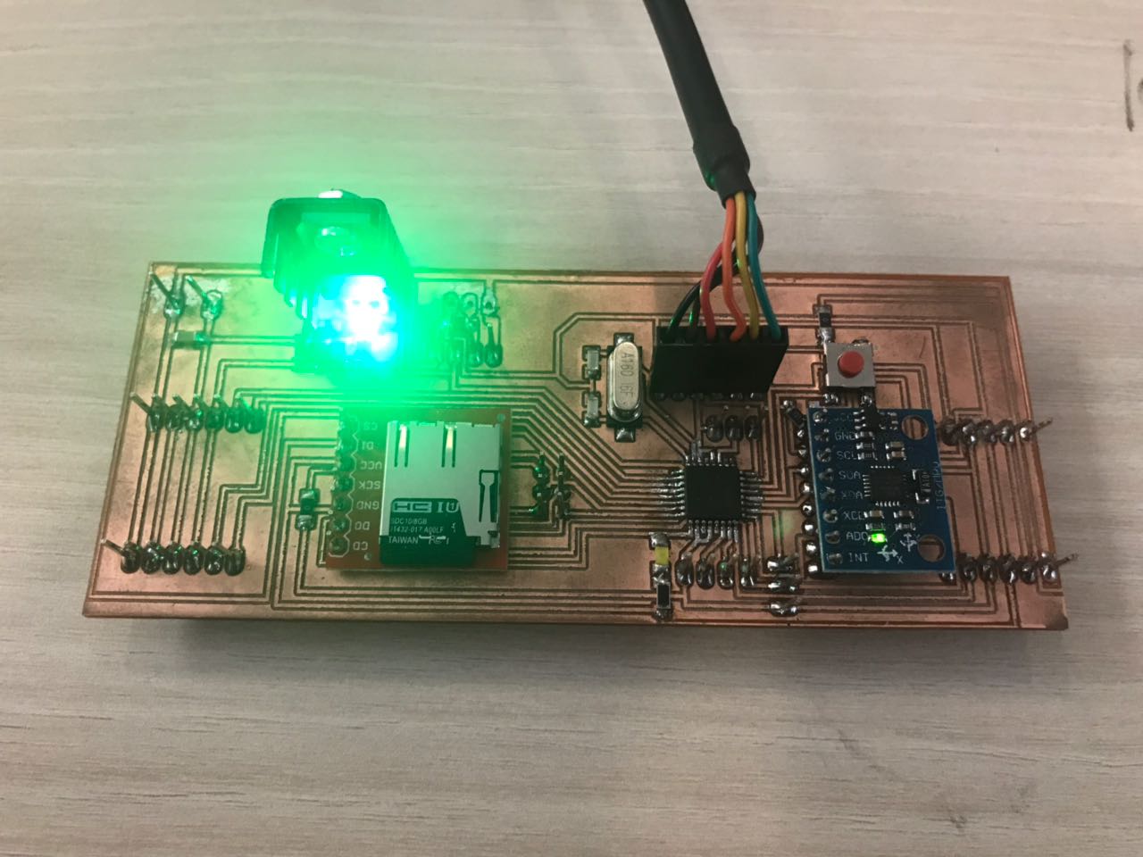
5 - Accelerometer and Gyro (MPU-6050)
The main sesnor i will be using in my Pipe Surveying Robot is the the MPU-6050.
The InvenSense MPU-6050 sensor contains a MEMS accelerometer and a MEMS gyro in a single chip. It is very accurate, as it contains 16-bits analog to digital conversion hardware for each channel. Therefor it captures the x, y, and z channel at the same time. The sensor uses the I2C-bus to interface with the Arduino.
The MPU-6050 is not expensive, especially given the fact that it combines both an accelerometer and a gyro. Also note that Invensense has combined the MPU-6050 with a magnetometer (compass) in a single chip called MPU-9150.
The accelerometer measures the acceleration along one direction, while the gyroscope measures the angular acceleration on one axis. The module has 8 pins:
- Vcc that could be connected to a 5V or 3.3V power suply. The MPU-6050 module has a voltage regulator on board
- GNG pin which is connected to the GND of the control board
- SCL which has to be connected to SCL pin of the micro controller, known by the Analog 5 pin on the Arduino Board
- SDA pin which has to be connected to the SDA pin of the microcontroller, known by the ANalog 4 pin on the Arduino board.
- XDA pin
- SCL pin
- AD0 pin
- INT pin
Open the Serial Monitor, move the sensor and try to see how the values change.
You can download the data sheet for the Accelerometer and Gyro (MPU-6050) from the following link Below is the code used to read data from the Ultrasonic Sensor
