Discovering Networking and Communication
There are many types of networking procedures that could be used to communicate between various microcontrollers, in order to widen the cpabilities of a certain system. Among those networking methods are:
- Serial Communication which is mainly communicating data using the serial connection between microcontrollers.
- I2C which mainly using the SDA and SCL pins to communicate between microcontrollers.
- SPI which uses the MISO and MOSI pins (ISP pinouts) to communicate between microcontrollers.
In this section, we will learn on how to connect two or more microcontroller boards, using different networking methods to communicte data between them.
Assignment
We had a Group Assignment and an Individual Assignment this week.- Group Assignment Send a message between two projects.
- Individual Assignment The individual assignment was mainly to design and build a wired &/or wireless network connecting at least two processors.
- Arduino IDE was used to write the code and upload the code.
You can check the Group Assignment on the following link: Group Assignment
Software Used
The following software were used for 2D Vector Design in this week's assignment:1- Group Assignment - Send a message between two projects
Test 1 - Testing Serial Communication
To achieve a serial communication between two microcontrollers, we need to take care of two parts:
- the wired connection between them
- the code used
With respect to the code, two different set of codes will be used on the different microcontrollers communicating. One of the codes will make the first microcontroller act as a Sender of the Data. So the board can be gathering data from a certain sensor and sending them to the other microcontroller using the serial terminal. On the other hand, the other board will carry the code that Recieves the data from the serial. In that case, the reciever could be using this data to control a certain output like an LED or a motor. Or we can simply read this data from its serial monitor.
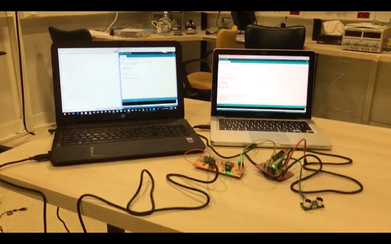
In our Group assignment, we decided to use our previously constructed boards. All details related to my board could be found on the following link. The boards were connected using Digital pins that were set as software serial. Note that the GND pins have to be connected on both boards. So the test was gathering data from the Ultra-Sonic sensor on the First Board, and sending this data to the other board, were we read the data from the serial monitor.
The video represents how the distance was collected from the first board, and sent to the second board, where we can see all details on the serial monitor.
You can download the original Arduino Codes Used from the following links:
2- Individual Assignment - Build a Wired/Wireless Network
In the individual assignment, I decided to test various types of Networking and Communication processes. We already tested wired serial communication between two boards, so the next step was to test other types of communication.
So in this week's assignment i tested all the following:
- I2C Communication
- Serial Communication using Bluetooth
- Communicating using Digital Inputs/Outputs
More details will be described below.
1 - I2C Communication
The I2C communication or Inter-Integrated Circuit is usually used when we want to share the workload of on microcontroller with another, or when we want mor digital or analog inputs/outputs.
To achieve this communication, we mainly need the I2C pins, that are SCL and SDA pins of the micro-controller. However, in my produced board, the MPU-6050 module occupies those pins and it is hard to use those pins.
So I chose to use Arduino UNO boards in this test, as they have the same processing power of my board.
To connect 2 or more Arduino Boards using I2C communication, we need to use the A4 (SCL) and A5 (SDA) pin, an connect them all in paraller, meaning we use the same pins on the other one.
Note that the GND line has to be common between all arduino boards that are communicating.
The video represents how the Master Arduino Board was communicating with the other two Arduino boards, and controlling the built in LED on pin 13.
Below is the Master code and Slave code used to communicate between the boards using I2C.
Master code
Slave code
2 - Bluetooth Communication
Bluetooth communication appeared to be easier than expected. In this test, I used the ZS-40 Bluetooth module which is known as HC-06.
The concept behind the communication is very easy. Technically, the Bluetooth module works as a middle man that carries the commands recieved wirelessly through bluetooth from any device that has buetooth connectivity to the serial pins of the Microcontroller.
In this test, I used an My Board with a Bluetooth module connected to its Serial Pins (Rx and TX). The idea was to be able to control an LED wirelessly.
So to do that, I followed the following steps:
- Connect the Bluetooth Module to the Arduino board (TX>RX; RX>TX; Vcc> 3.3V; GND to GND)
- Download the code to the Arduino board
- Connect to the bluetooth module using a Laptop
- On the Arduino IDE, choose the Port to be the Bluetooth port and then open the serial monitor
- Enjoy controlling the LED by printing 0 or 1 on the serial monitor
Below is the code used for bluetooth communication.
You can also download the Data Sheet from the following Link
The video represents how the system works.
3 - Digital Input/Output Communication
After testing the Serial, I2c and Bluetooth communication procedures, i wanted to test another way of communication that is based on traditional logic on and off commands, close to using a push-button.
So the theory is mainly communicating between two boards using Digital Inputs/Outputs pins. On the first board i used two digiatal pins, one that is set to be an input and the other to be an output. At the input pin, I connected a pushbutton. On the other hand, the putput pin is connected tot the input pin of the other Arduino board.
On the other board, one pin is set to be an input and the other is set to be an output. The input pin is connected to the output pin of the first board. As for the output pin, it is connected to an LED.
So the logic goes as the following:
- The First Arduino board senses that the push-button is pressed at the input digital pin
- Next the First Arduino turn on the output pin(set pin HIGH)
- The input pin of Arduino Two will then sense a High voltage just like reading a push-button
- The Arduino Two then turns on the output pin thus turning on the LED
This represents a very simple concept of serial communication using only one On or OFF command.
The code below is the code used on both boards.
You can download the original Arduino Code Used for both boards from the following Link
