Discovering Machine Design
This week had a wide range of ideas that could be done. Many ideas could be found in previous Fab Academy years and on other online resources. We can make a CNC Machine, a plotter, laser cutter, 3d printer and many other more, all of which have the same main concept, a sytem of stepper and servo motors, that control a specific head, to produce a specific final product.
We had a Group Assignment for two week.
- Week 1 - Group Assignment The group assginment was to design a machine that includde mechanism, actuation and automation. We had to build the mechanical parts and operate it manually.
- Week 2 - Group Assignment The assignement of the second week was to actuate and automate our machine.
Machines Used
The main machines used in this week's assignment are the CNC Machine, Laser Cutter and 3d printers.- Epilog Fusion M2 120 Watts was used for laser engraving and laser cutting in this assignment. This Epilog Fusion M2 uses the CO2 Laser Technology to cut and engrave. The laser source is guidged by 2 axis (X and Y) that guide the focal point of the laser where cutting will occur.
- Shopbot which is the biggest CNC Router we have in the lab.
- Ultimaker 3 and Ultimaker 3 Extended is one type of the FDM 3d printers. It was used for 3d printing small scale objects up to 20x20x30 cm.
- Form 2 is our SLA 3d Printer. It was used for high-resolution prints.
Software Used
The following software were used for 2D Vector Design in this week's assignment:- Fusion 360 was used for 3d modelling in this assignment.
- CorelDraw was used to make fast 2D designs mainly for testing the different capabilities of the Laser Cutter. It is an easy software that could be used for color mapping.
- AutoCad was the main software used for 2D design. I used it to design the Press-Fit Kit.
1- Mechanical Design and Production
Brainstorming
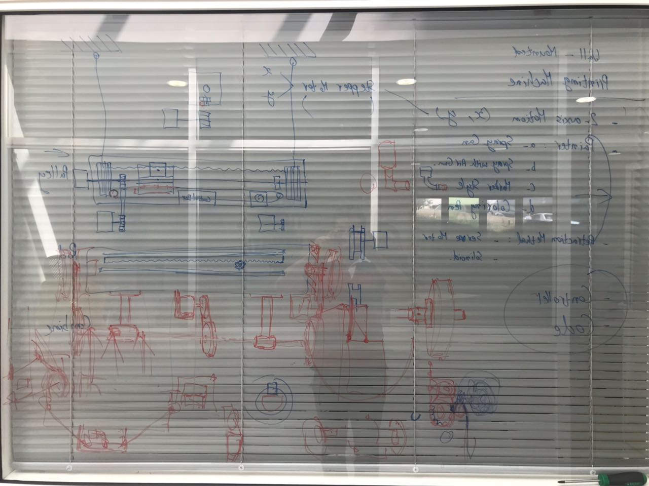
So the first step in this project was to design our machine after many brainstroming sessions. We had many different ideas that could achieve the same result. However, as all brainstorming sessions, ideas changed rapidly and we tried our best to keep the idea feasible and doable in one week.
We first wanted to build a machine that could paint on a wall, either using spray paint, a roller, or anything that could apply paint on a wall. However, using spray paint would complicate the machine, especially if we want to used compressed air. So we decided to scale the project down and use the concept of a highlighter, meaning a sponge head to apply the paint on a wall. The idea is that the spongy head, which is 5cm x 5cm will apply paint by pushing on the wall, leaving a 5x5 square. So we can draw a big image on any wall, by converting it into monochrome image, and printing it in pixels on the wall.
Preparing the 3d Design
The 3d model of our project was built on Fusion 360, mainly because you can build the different components on the software and assemble them together on the software. THe various parts that were mainly included in the machine design were the following:
- Rack and Pinion system that will achieve the horizontal left and right motion
- Frame of the machine that is designed to be made of 1cm thickness MDF and assembled using nuts and bolts
- Pulley system that will achieve the Vertical up and down motion
- Coloring Tank that will carry paint inside it
- Paint Applicator which constitute of a tube that moves along one axis, and pushes the painting head on the painted surface
- Main Plate that will carry the paint tank, the applicator, and the steppr motor connected to the pinion. This plate with the rack and pinion system is what provides the horizontal motion
- Front Wheels that will guarantee a constant distance betweent he machine and the surface as they roll on top of it
Manufacturing the Different Parts
After preparing the 3d design of the whole machine, the next step was to start manufacturing the different parts. Each part was produced using a different technology available in the lab, to achieve the best final product.
The main digital fabrication tools that were used in this project was the following:
- Epilog Laser Cutter
- Shopbot CNC Milling Machine
- Ultimaker FDM 3d Printer
- Form 2 SLA 3d printer
CNC Machining
Most of the parts in our machine were produces using the CNC milling machine, mainly the main frame of the machine and the various parts that formed the pulleys. The DXF files were extracted from the sketches of the Fusion 360 design and then inserted on Vcarve to produce the g-code, which will then be used to machine the parts. All the parts were milled from a !cm thicness MDF sheet. You can download the original files used for machining from the following link CNC Machining Files
Laser Cutting
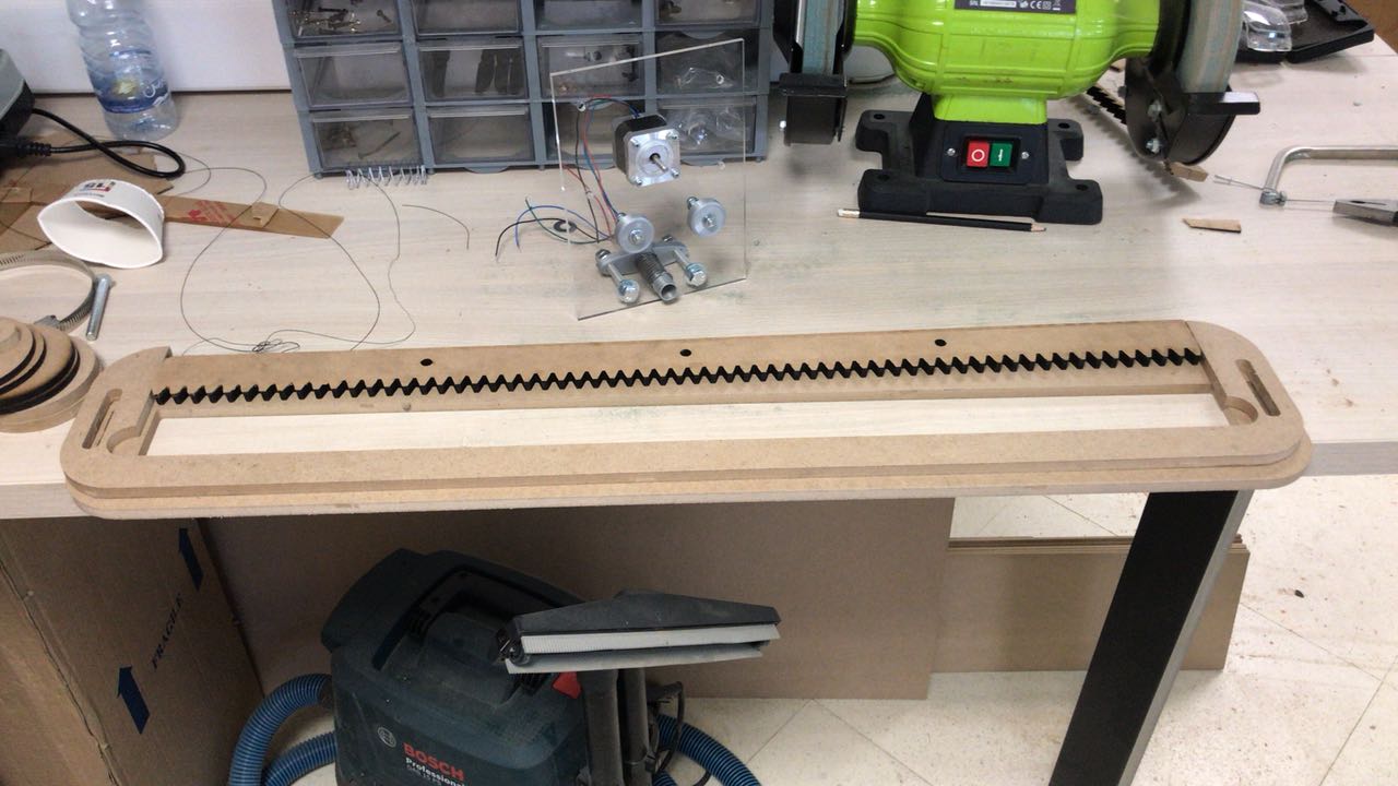
Other parts required high pricision in the production process, mainly the Rack gears, as they were hard to produce using cnc milling due to the small distance between the rach teeth that cannot be covered by the milling bit we have in the lab. The rack was produced from a 1cm thickness MDF plate.
The other part that was laser cut was the Main plate that will carry the painting kit. This part was cut from a 5mm thickness Acrylic sheet.
You can download the original files used for machining from the following link CNC Machining Files
3d Printing
Various parts were produced using 3d printing, mainly the 3d parts that we were planning to produce in plastic and flexible material.
Two different 3d printing technologies were used for the production process:
- FDM 3d printing using the Ultimakers
- SLA 3d printing using the Form 2
Also diffrent material were used for the different parts printed
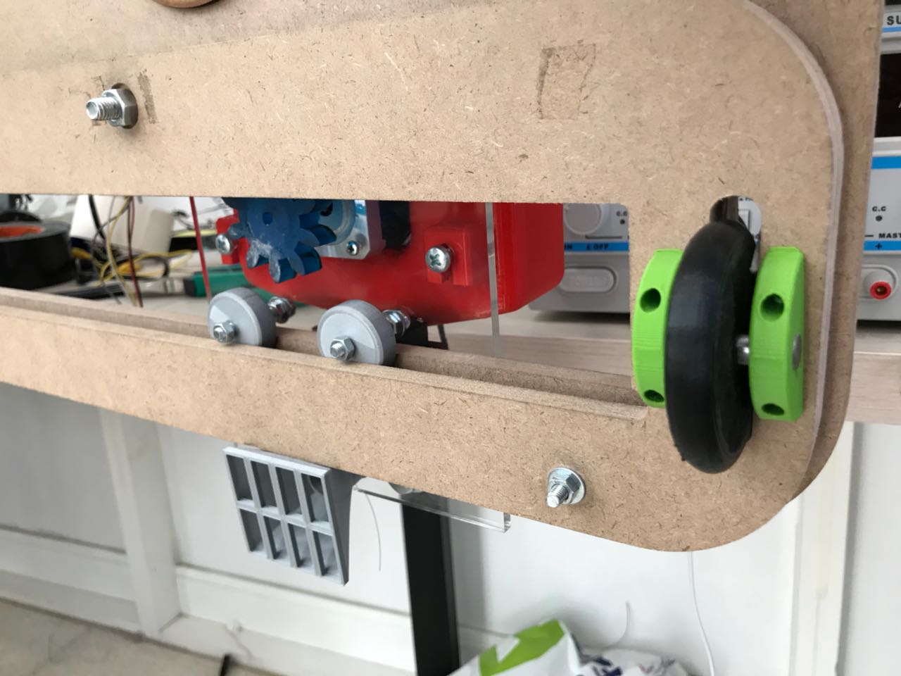
- Silver PLA were used for the wheels that will carry the main plate on the rail.
- Silver PLA was also used for the printing head and the tube
- Red PLA was used for the main tank that will carry the painting material
- Green PLA was used for the support that will carry the Front wheels
- Black PLA was used to printing the Servo Motor Stand and Pulley
- Black NinjaFlex, is the fexible material used to print the fron wheels to profide traction with the painted surface.
- Tough Resin was used to print the Pinion gear.
You can download the original files used for our tests from the following links: 3d printing files
2- Assembling the Machine
After producing all the different parts using the different technologies, the next step is to assemble all parts together to make a functional machine.
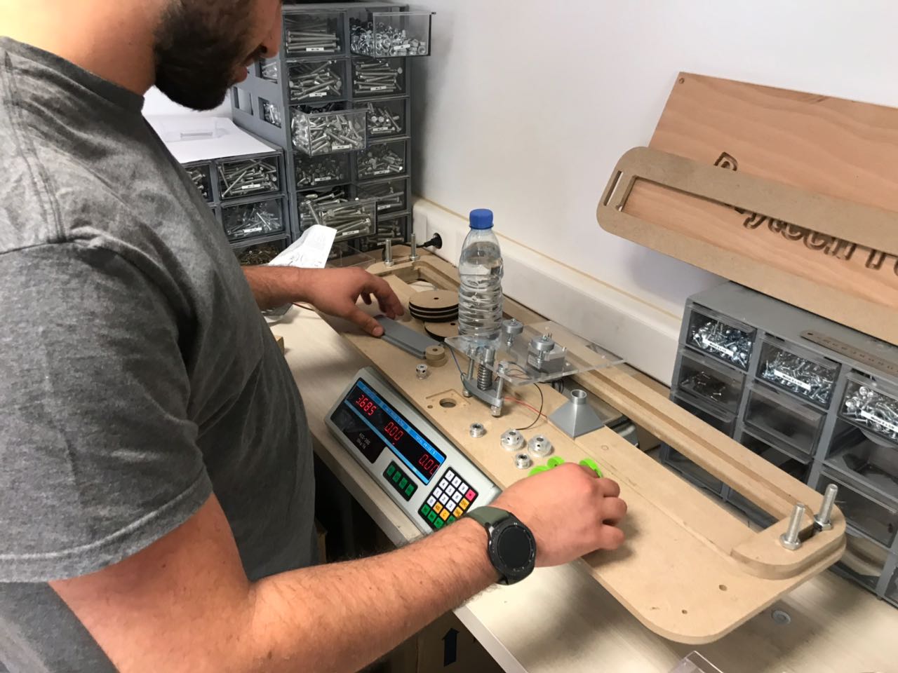
Preparing all parts
Before final assembly of the machine parts, the first step was to make sure that they all fit together, in order to make final edits before assembling. All the different parts were tested together, to make sure that they will achieve the job they are meant to do. All parts fitted perfectly together, but the pinion gear was getting stuck between the guiding plats, cause the MDF plate used was not a perfect 1cm, in fact it was 9.5 cms. So we had to do some edits on the pinion gear and re-print it so it can move loosly.
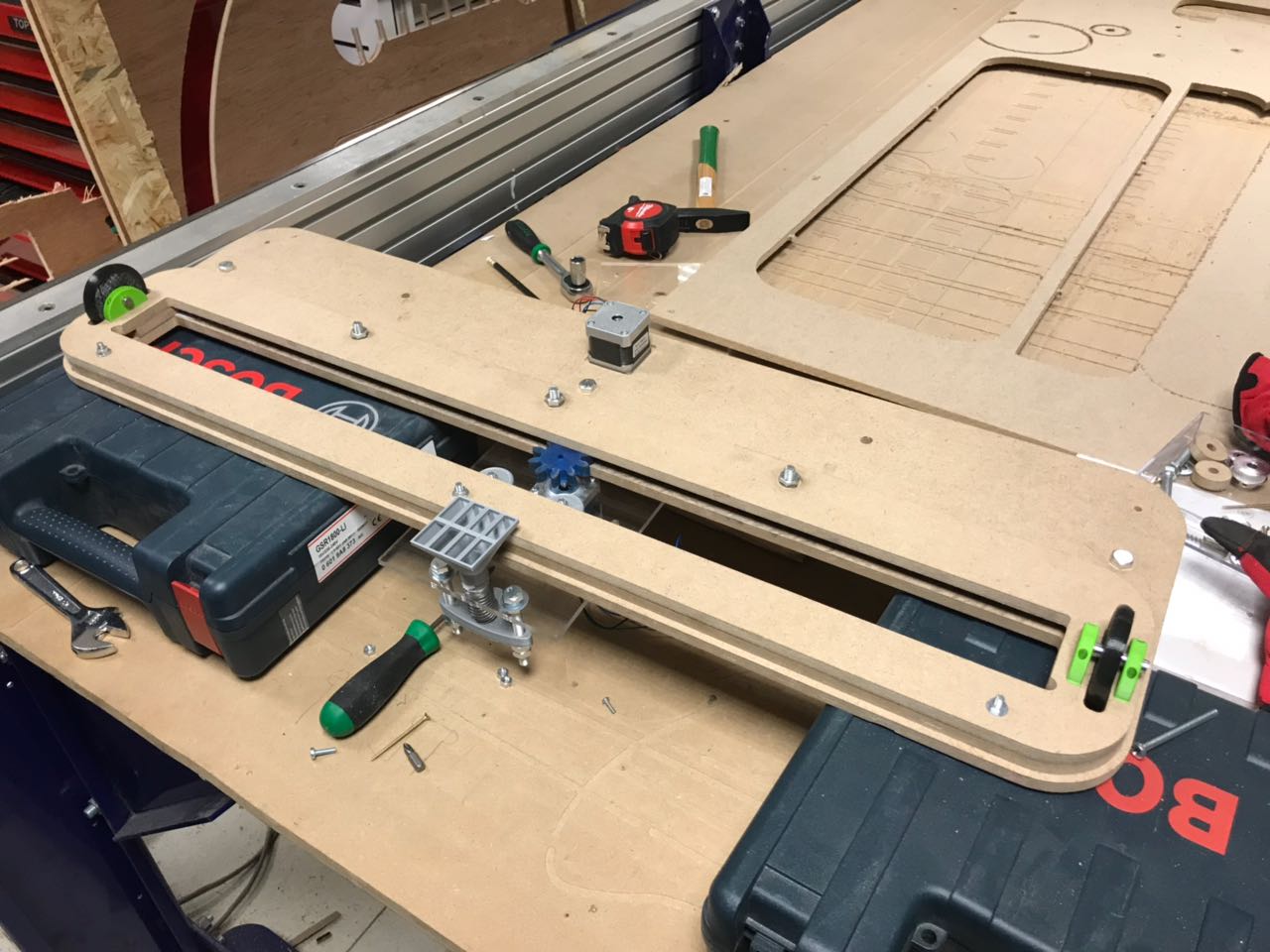
Assembling the Machine
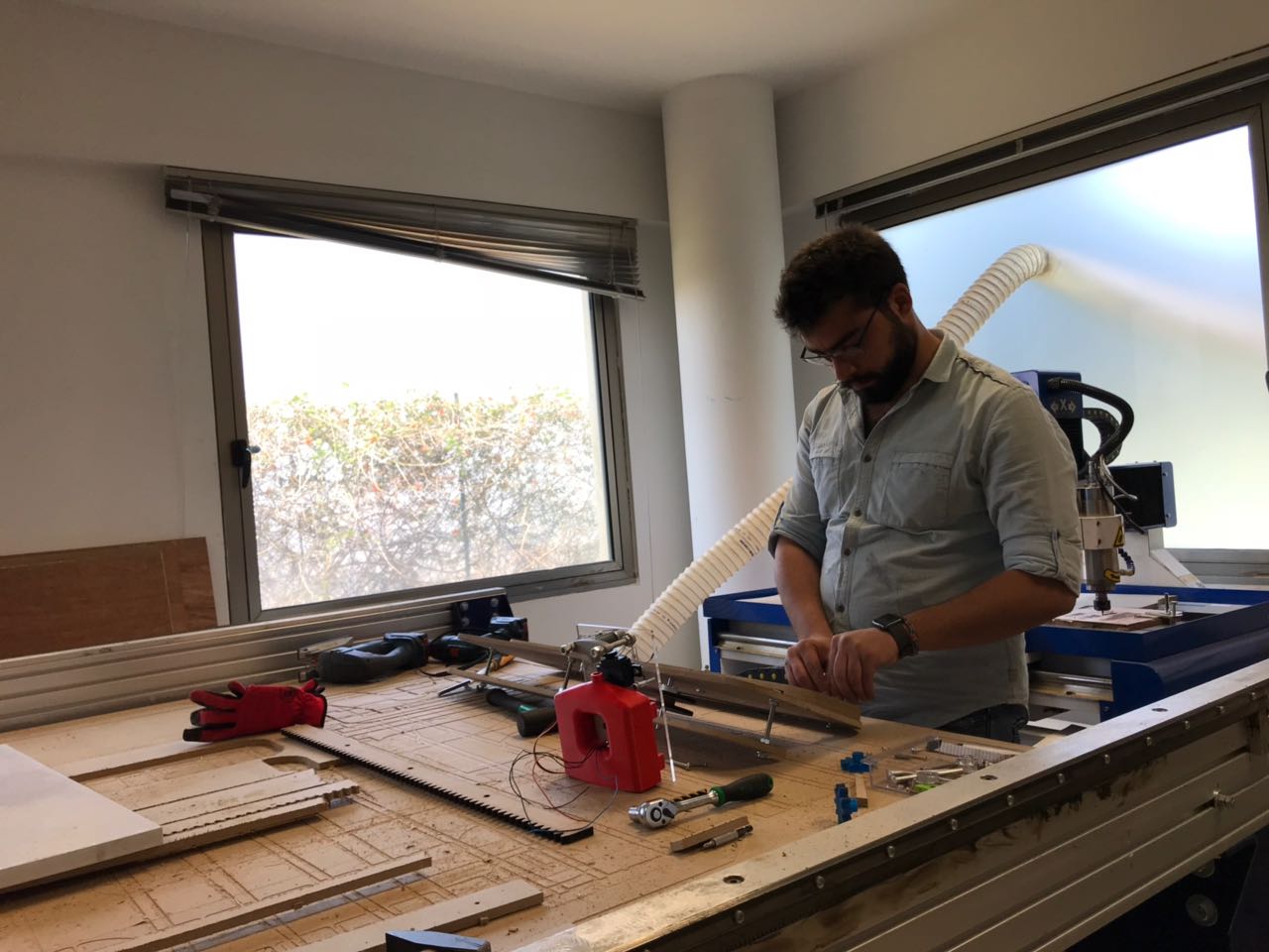
Next we assembled all parts and we tried to test that all parts move as they are supposed to move before starting with the electronics and control part. As a first step, we made sure that the main mounting plate, that will carry the paint applicator, moves freely on the horizontal axis, on the designed rail. It worked.
Next we assembled the pulley system using the CNC milled pulleys and chasis plates, and a set of standard GP2 pulleys and belt. In addition, guiding rods of diameter 8mm were used as the asxis for the main pulleys that will carry the puuling cable. A 20 tooth pulley was fixed on the axis of the Nema 17 stepper motor, and a 40 tooth puller was fixed on the axis of main pulleys. This would achieve a 2:1 gear ratio between the source and the driven pulleys, thus achieving a higher torque.
Testing the Machine Mechanism
After assembling all parts of the machine, and making sure that each part does its specific job, the next step was tomake sure that the whole system works correctly all together before installing the electronic components and working on the control part.
The video below shows how the system worked by moving it manually by hand. Both the horizontal motion and the pulley system worked according to the designed concept. The next step is to start controlling it and checking if it works for real.
3- Preparing the Electric Circuit and Code
After preparing all the mechanical parts of the machine, the next step was to install all the electro-mechanical components such as the Stepper Motors and Servo-motor and build the electric circuit along with the control of the circuit.
Based on the needed circuit, the code that will be downloaded on the micro-controller and that will control the machine was written accordingly.
Two different scenarios were followed to control our machine:
- Scenario 1: Controlling the machine manually using a joystick. This will allow us to move the machine and print on demant by a push of a button
- Scenario 2: Controlling the machine using a g-code generated using any g-code generaotr, by the help of the GBRL software uploaded on the controlling Arduino Board
Components Used
The main electronic components we used in this machine are the following:
- NEMA 17 JK42HS40-1304F, that controlled the horizontal and vertical motion of the painting head
- Stepper Driver A4988 that was used to control the stepper drivers used
- Servo Motor DSS-P05 that was used to push the paint applicator forward and backwards
- Joystick that was used to control the machine maually.
Controlling Code - Example 1
After Designing the system and connecting all the components that we are using in this machine, the next step was to write the controlling code. the first option we designed a manual option of controlling the machine using a joystick, Left Right for x axis and Up Down for the y axis, pressing the middle button would activate a 180 degree cycle on the servo to control the z axis.
The first video represents how the code control the different electric components before installing them on the machine on the machine. The joystick controls the two stepper motors and the servo motor.So we first made sure that the system theoretically works.
Next we added the electric components to the mechanical parts of the machine. The horizontal axis worked as wanted, as shown in the second video. However, due to the weight of the machine, the vertical axis wasn't efficient as the motor was not able to pull the system to the top. Plus the rope was locking inside the pulleys due to the whole system's weight. So the only functional use on the vertical axis was mainly using the stepper motor as a breaking system. So if we start the machine from the top, we can go down to a certain level and then stop by the help of the stepper. But also, some slippage occured which caused the horizontal to be oblique.
You can download the Arduino code used from the following Link
Controlling Code - Example 2
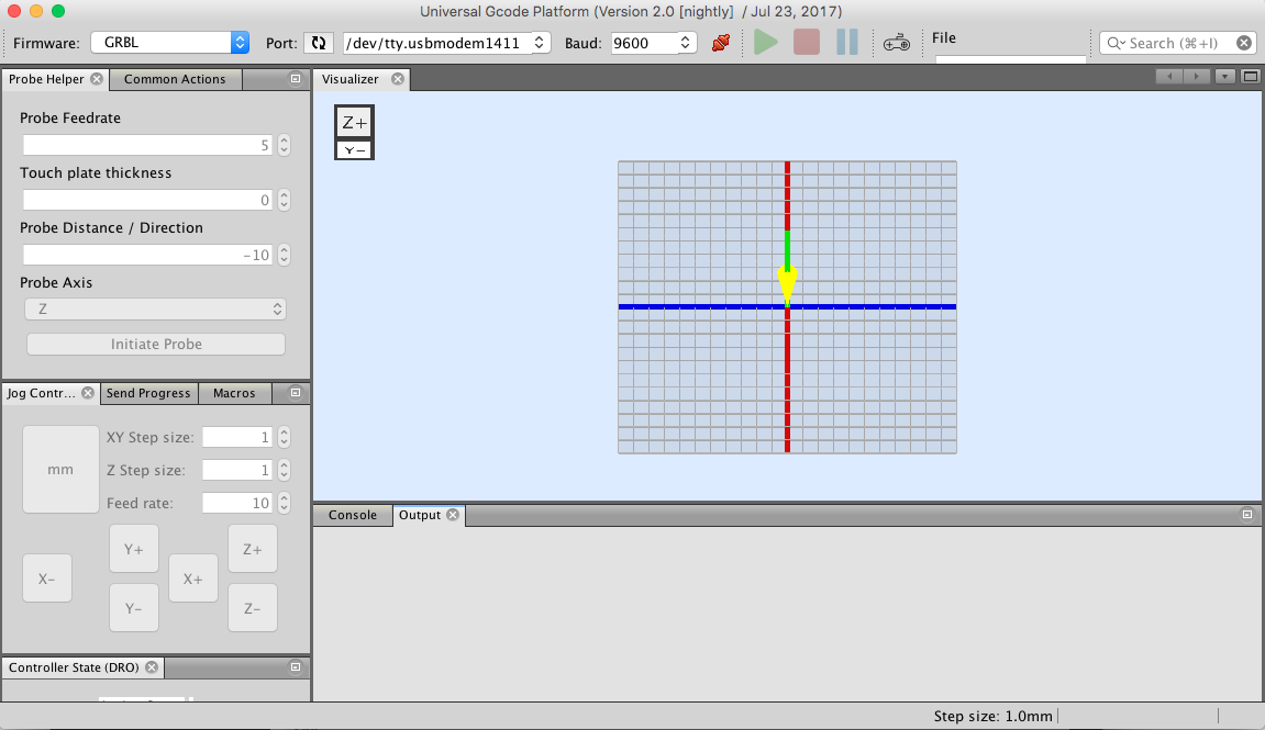
The second option was to completely automize it by using a G-code. The G-code could be generated using Fab modules and sent to the Arduino that has the GBRL software previouly uploaded on. Next using a software called Universal g-code sender (by UGS), we will feed the commands to the machine. This option is still not fully functional as it still needs a lot of calibration on the g-code.
To test this option, the following stepps were followed:
- Download the UGS (Universal G-code Sender) to be able to control the machine using the on-screen control panel, and to send the g-code t the machine once it is ready. In our case we used 1.0.9
- Download the GBRL v1.1 file, which the g-code parser.
- Download the G-code library and then upload the "GBRLtoArduino" Example code onto the Arduino board
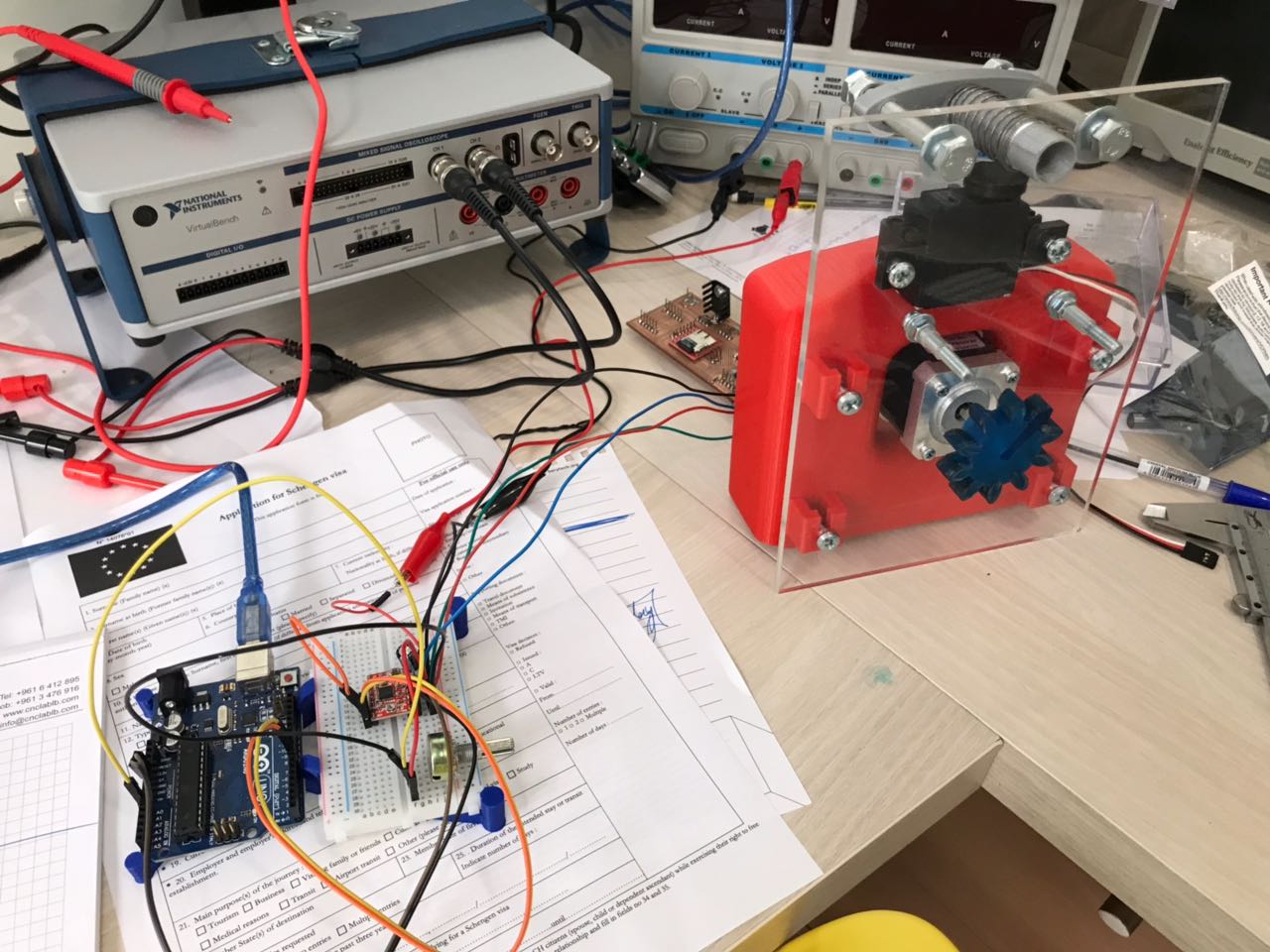
- Make the connections to the Arduino according to the image. The stepper motors are not directly connected to the Arduino board. It is connected to the Stepper driver, Polulu a4988, that is connected to the Arduino board using 2 digital pins, one used for the steps and the other used for the direction.
- Once all connections are made, and all the codes are downloaded, the next step is to connect the Arduino board to the computer and open the UGS software Generate a g-code using fab modules by inserting a monocrome image in png form. Then save the g-code on the computer.
- On the UGS software, choose the port where the Arduino is connected, and upload the g-code using the browse button.
- Once everything is ready, send the gcode to the board and enjoy. You can simulate the proces by clicking the "Visualize" button
For the same reason mentioned before, the machine could not be operated due to the weight of the machine which was causing locking on the vertical axis.
For more details, please refer to my colleugues page using the following link: Ghassan's Page