Ideation Process
This gathered information will be used later by engineers to design and upgrate water supply systems and oil and gas systems more efficiently.
To build this robot a long ideation process was followed which caused the design to change and get upgraded with time reaching the final design.
Robot Capabilities
The following main capabilites must be achieved for it to be successful:- Motion in all directions
- Capability to detect obstacles and stop
- Capability to gather angular and position data
- The ability to regulate position according to the measured angular data
- Capability to store the data on an external microSD memory card
Limitations
So in order to achieve those capabilities, many points and limitations that would affect the design were taken into consideration.Among those limitations are the following:
- Pipe Architecture which mainly is a cylindrical shape. So the robot has to be able to move on a circular path rather.
- Pipe diameter The robot has to be able to survey pipes of various diameters, thus it must have a mechanical design that would achieve that.
- Pipe Internal Surface The pipes could be mainly made of various material mainly concrete, composites or carbon steel. Adding to that the material that the pipe is carrying. Thus the surface could be slippery. So we need a robot that could handle slippery surfaces
- Pipe Fittings The pipeline has many pipe fitting on the way such as 90 degree and 45 degree elbows, plus some reducers. Thus the robot should be able to recognize those fittings and operate accordingly.
- Motion Errors Because life is not so easy, and many forces will affect the robot, most probably, the robot will rotate in the pipe causing an error in the collected data. So the robot has to calibrate its position every once in a while to remove this error.
Research
A wide research was done before starting with the design process.Existing Projects
The first research i did was to check the available systems and designs that would achieve the objective i want.Many pipe inspection robots done before could be available online, mainly as videos on You Tube. Those various projects differ by the scale, mechanisms and technologies they are using to achieve the same job, but with different efficiencies. However, those Robots have one of two objectives:
- Pipe Inspection which is checking and inspecting any deformaties, problems, and irreguarities.
- Pipe Repair and Cleaning that mainly fixes the irregularities in pipes.
Electronic Components
In addition to that, an intensive research was done to check what electronic components are available that would help us achieve what we want.We require a set of inputs (sensors) that will be used to gather data, and outputs that will save the data collected in the bot's trip inside the pipe, and control the movement of the robot.
So the set of sensors and electronic components that I plan to use are the following:
- MPU9250 - Gyro Sensor that measures the angle of the bot with respect to the ground. One of the most used Gyro sensors in the market that i will be using is the MPU9250: 9-DOF 3-Axis Accelerometer, Gyro, & Magnetometer
- Ultrasonic Sensor that measures the distance the bot has until it hits a wall or an obstacle, to prevent the bot from being stuck inside the pipe. This sensor will also be used to confirm the existance of elbows in the pipeline. The cheapest and most used distance measuring sensors used in the market is Ultrasonic Sensor - HC-SR04
- Stepper Motor with Rotary Encoder that is both an output and input at the same time. So the stepper motor produces motion and at the same time it records the number of rotations done, thus measuring the distance. One of the most used stepper motors in the market that i will be using is Nema Stepper Motor
- SparkFun microSD Transflash Breakout that is used to save the collected data on an external microSD Flash drive. I decided to use the SparkFun microSD Transflash Breakout
Software Used
The following software were used in this week's assignment:- AutoCad was mainly used by me as a fast and precise sketch book, mainly to visualize how my Final Project is going to look like, the various options I have, and the limitations I have that affect the design.
- Fusion 360 was mainly used to 3D model the various mechanisms and various parts that my final project will be using.
1- Primary Designs
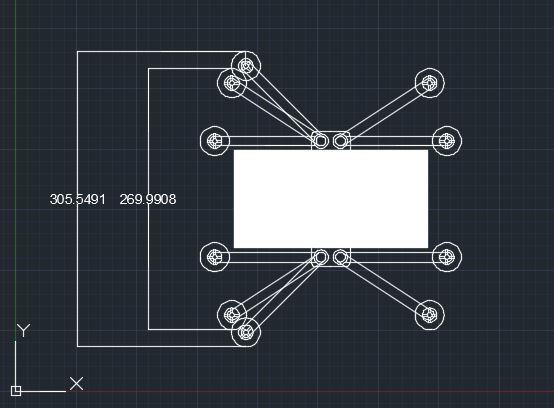
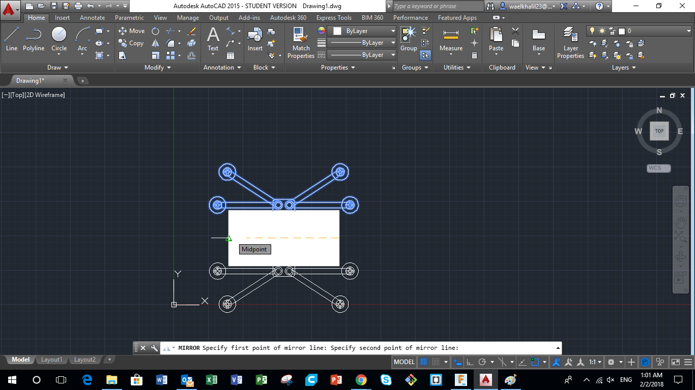
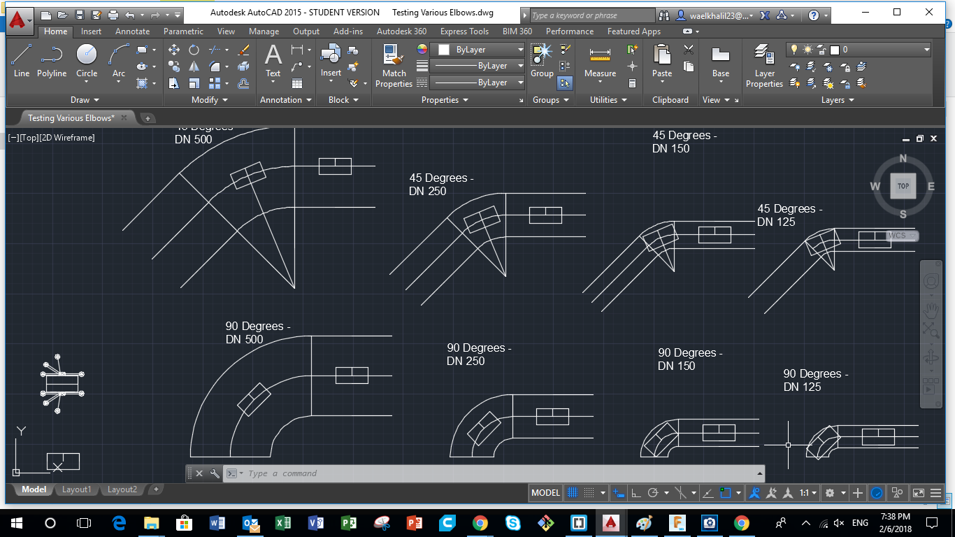
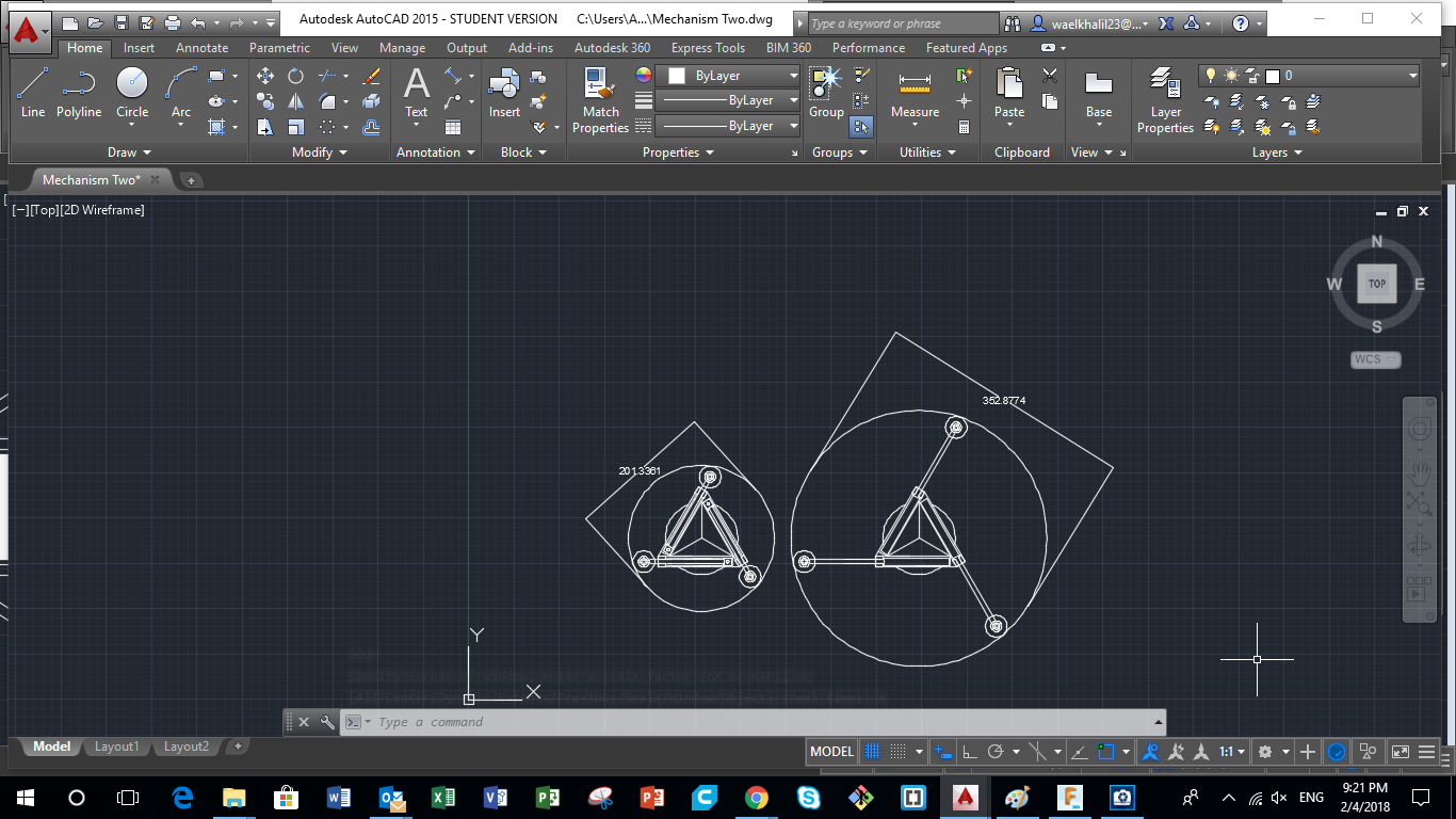
In order to visualize the various designs, my "Pipe Surveying Bot" could have, and the various limitations that affect the size and the shape of the bot, i used AutoCad. I tried to draw the various mechanisms that i could use for my design and the different dimensions of pipes my bot can survey based on the proposed design. Below are some designs that were used to build the general points i should be taking into consideration to reach my final design.
You can download the original files from the following links:
Drawing the Main Body
The Main body is where the electronics and main components that control the system will be located. So First i had to start by drawing the Main Body.
Based on my experience in the field, water supply pipes could vary between 4" (100mm) and 30"(750mm) in diameter. However, most used pipes are between 6" (150mm) and 18" (450mm), and that was my main target. I had to think of a tiny main body for the Bot that could fit in all those pipes with different diameters.
Saying that, I chose to have the main body to be cylindrical in shape with a length of 20 cm and a diameter of 10 cm.
The image also represents one mechanism that would help achieve what we want.
Visualizing Pipe Limitations - Fittings
The next step was to have some drawings that would help us visualize how easy the Bot can move inside a pipe, especially at the fittings (90 degrees and 45 degrees elbows ). Saying that I drew various elbows and pipes of various diameters, and i inserted the Main Body in each one to visualize how much freedom we have.
Drawing Various Machanism Designs
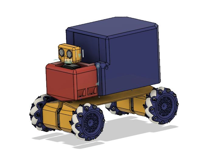
Various mechanisms were designed that would achieve the same objective, which is the ability to move inside pipes of variable diameter. My primary idea was using 6 wheels, 3 on each side, that are equidistant to each other. Another had extendable legs, piston like legs, that are located at the edge of the Main Body. When the pistong open and close, the wheels will expand to reach various pipe dimentions.
3D Modelling the Primary Design
After sketching the primary design, a 3d model for it was made in order to 3d print it and visualize how it will look like. The Main Body will carry all the important components of the Bot, and where all the other parts will be connected. The video attached shows how the final design shown below was reached.
You can download the original files from the following links:
3D Models of the Robot Legs
Attached here is the 3D Model of the Legs. Feel free to explore my design and check out all the details.
Primary 3D model of Wheels
In the primary design, i wanted normal rolling wheels that will drive the robot like any normal car.
A 3d model of the primary wheel design is shown.
3D model of Second Design
After design the first Main Body, I recognized that I have some limitations concerning the maximum diameter the bot can reach. Saying that, i tried designing another mechanism that could be used for my Pipe Surveying Robot. The idea is having piston-like legs fixed at both ends of the Bot, which will expant and contract, thus achieving various pipe diameters, with more stability. The video shows how I reached my final design.
3D Modelling Piston Legs
Now I had to design new legs that are piston-like, having adjustable dimensions. Those legs will be installed in the cylinders shown at the edge of the Main Body in the previous design shown. The video shows all the steps followed to achieve this design.
PCB 1st Sketch Design
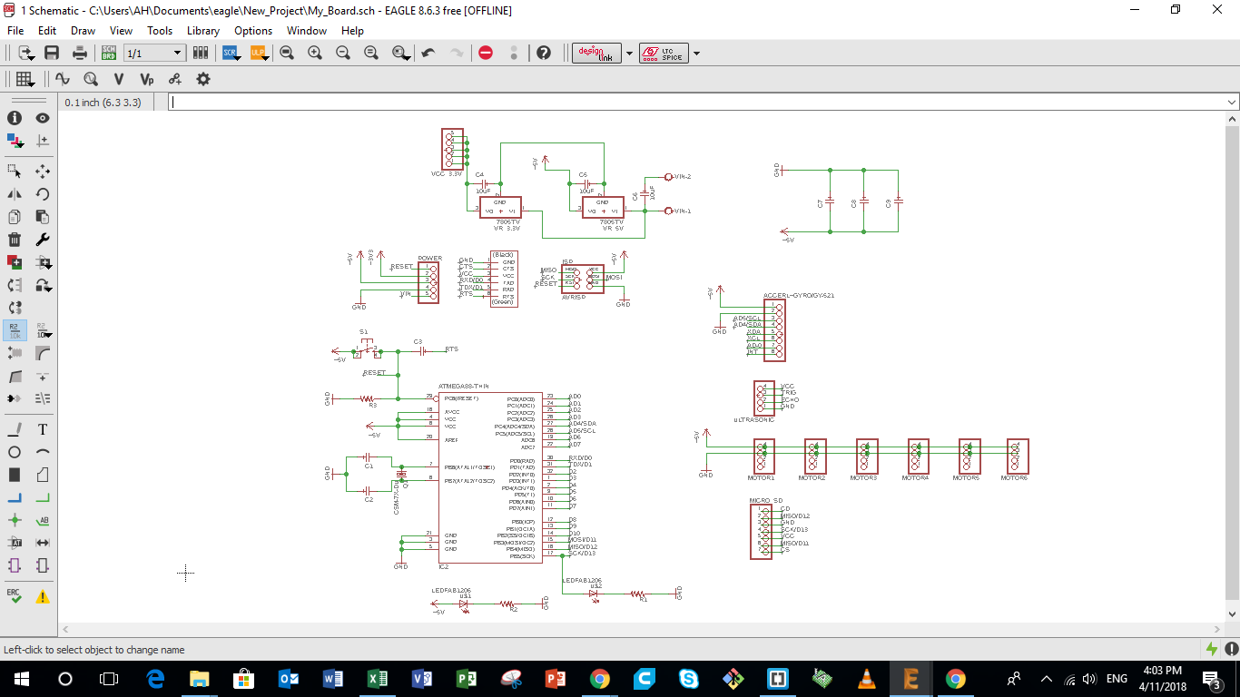
Next i needed to design the control board of my pipe surveying robot i am building. Many points had to be taken into consideration while designing the board, mainly the Architecture of the Microcontroller i am using, the pin connection to the sensors and outputs i am using. The different parts of the Control board are described in details below. The image represents the different part of the full control board such as: Microcontroller Power and Input Pins Inputs and Output Pins Power Board.
PCB 1st Board Design
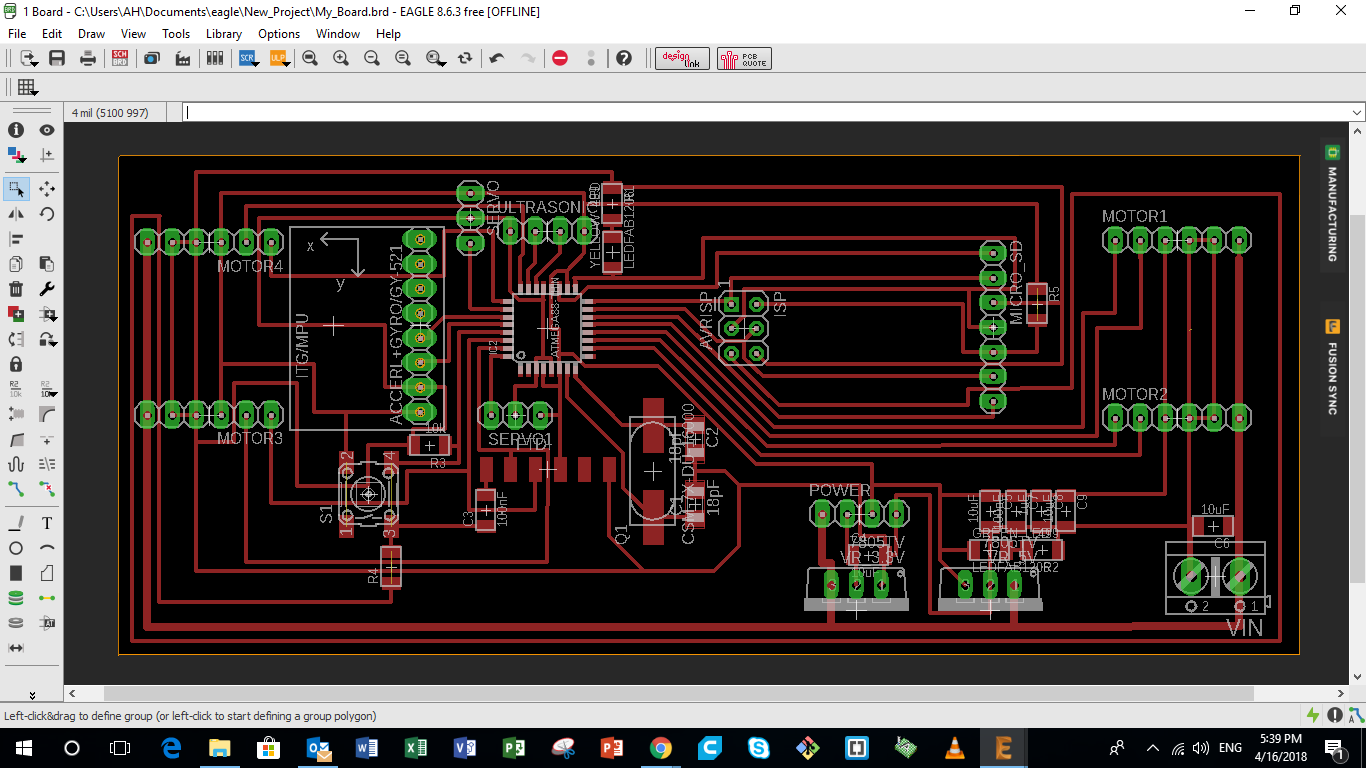
After inserting all the components i wanted in my first board, the next step was to design the board layout.
The image attacehd shows the design of the first board.
The first board has an MPU-6050 on board to gather Angular Data. However, it lacked a Magnometer that was available in the MPU-9250 which was used in the final design. It also hada Micro sd transflash on board to save the measured data. The board also had 4 pinout for 4 stepper motor. It was designed this way because i was planning to use stepper motors with Stepper Motor Drivers near them. However, in the Final design, the board had 4 Stepper Motor Drivers on board.
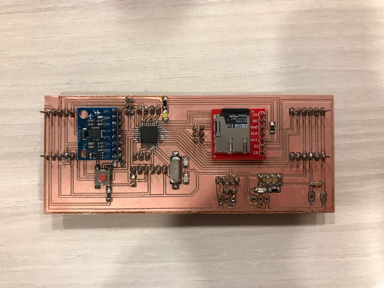
Production of first Board and Testing
After finalizin that, the next step was to produce the PCB. The PCB was first milled from a coper board, the components were soldered on it, and then the firmware was downloaded on the board. After that the board was tested with all the inputs and outputs that i was planning to use in my robot.
Final Mechanical and Electrical Design
After trying various mechanical and electrical designs, the design was enhanced and shifted from the primary design.
You can find more details of the Mechanical design on the following link.
You can find more details of the Electrical design on the following link.