PCB Design
Software Used
The following software were used in this week's assignment:Pinout Connection of My Components
So in order to build the board that will be controlling the PSB, i had to make some research regarding the differnt components i am using in my project, in order to design the board according to its architecture and technical specifications.
The robot has various inputs and outputs that will connected to the PCB. The inputs are:
- Ultrasonic Sensor used to measure distance
- Accelerometer and Gyroscope used to measure angular acceleration and the angular position
- Nema 17 Stepper Motors that will be used to drive the robot. I will be using a DRV8825 Stepper Motor driver to control the Stepper motors in my system.
- Servo Motor used to help scan the area when the robot reches an abstacle
- SparkFun microSD Transflash Breakout used to save the data collected by the robot
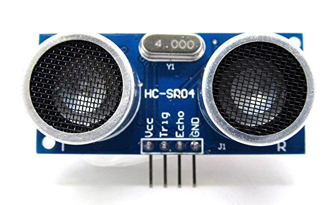
Ultrasonic Distance Sensor
As mentioned above, the Ultrasonic Distance Sensor is a Digital Sensor. The HC-SR04 Ultrasonic Sensor Module has four pins:
- Vcc which is connected to the 5V power source, either from the Arduino Board, or any other board
- Trigger pin which is connected to a digital pin which will be set as an output pin
- ECHO pin which is connected to a digital pin that is set to be an Input
- GND which is connected to the GND of the power source or board you are using
You can download the data sheet for the Ultrasonic Ranging Module HC-SR04 from the following link
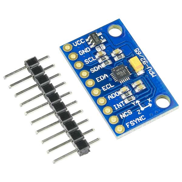
Accelerometer and Gyro (MPU-9250)
The main sesnor i will be using in my Pipe Surveying Robot is the the MPU-9250.
The InvenSense MPU-9250 sensor contains 3-Axis Accelerometer, Gyro, & Magnetometer MEMS in a single chip. It is very accurate, as it contains 16-bits analog to digital conversion hardware for each channel. Therefor it captures the x, y, and z channel at the same time. The sensor uses the I2C-bus to interface with the Arduino.
The MPU-9250 is not expensive, especially given the fact that it combines Accelerometer, Gyro, & Magnetometer.
The module has 10 pins:
- Vcc that could be connected to a 5V or 3.3V power suply. The MPU-6050 module has a voltage regulator on board
- GNG pin which is connected to the GND of the control board
- SCL which has to be connected to SCL pin of the micro controller, known by the Analog 5 pin on the Arduino Board
- SDA pin which has to be connected to the SDA pin of the microcontroller, known by the ANalog 4 pin on the Arduino board.
- EDA pin
- ECL pin
- AD0 pin
- INT pin is connected to the GND of the control board
- NCS pin
- FSYNC pin
You can download the data sheet for the MPU-9250 9-DOF 3-Axis Accelerometer, Gyro, & Magnetometer from the following link
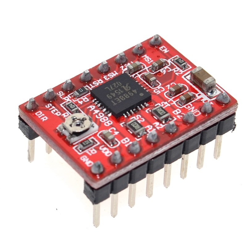
Stepper Motor - A4988 Stepper Motor Driver
I will be using the Nema 17 stepper motor as the main driver of my Pipe Surveying Robot. In that case, i can keep track of the exact distance that the robot cover inside the surveyed pipe.
In order to drive the Nema 17 stepper motor, I needed a stepper motor driver. I chose to use the Polulu a4988 stepper motor driver because it is cheap an small, and could be easily located on my PCB.
The A4988 module has 16 pins, among which only 12 will be used:
- Vcc that is connected to a 5V power suply.
- GNG pin which is connected to the GND of the control board
- VMot that will be connected to the 12V power suply. This is the voltage supplies to the Stepper Motors
- GNG pin which is connected to the GND of the control board
- Step pin which is connected to a digital pin which will be set as an output pin. This controls the number of steps of the stepper motor
- Dir pin which is connected to a digital pin which will be set as an output pin. this control the direction the stepper motor should rotate
- 1A, 1B, 2A, 2B pins are the pins that the stepper motor connects to.
You can download the data sheet for the Polulu A4988 Stepper Motor Driver Carrier from the following link
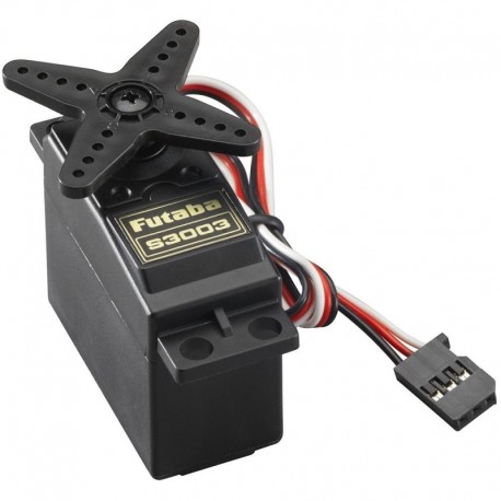
Servo Motor
In order to be able to scan the area when the robot reaches an obstacle, the Ultrasonic sensor will be fixed on top of a servo motor. The servo motor i am using, Futaba S3003 has 3 pins:
- Vcc that is connected to a 5V power suply.
- GNG pin which is connected to the GND of the control board
- Signal pin which is connected to a digital pin which will be set as an output pin. This controls the angle of the servo
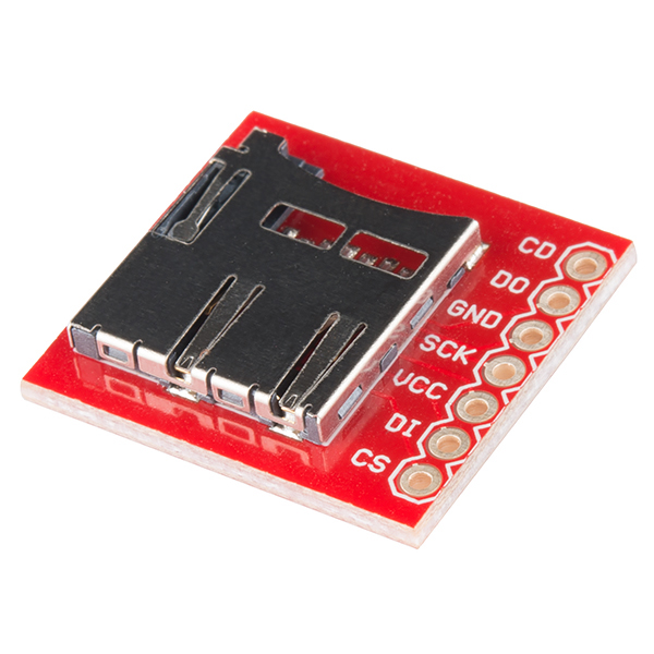
Micro Sd Transflash Breakout
The main tool i will be using to save the data collected by the robot is the microSD Transflash Breakout.
Breakout board for the microSD socket that is not much bigger than your fingernail. Compatible with the SPI interface found on any SD card, this tiny form factor was created for cell phone storage and is perfect for your next MP3 project! Board comes fully assembled and tested.
The microSD Transflash Breakout has 7 pins:
- Vcc that could be connected to a 5V or 3.3V power suply.
- GNG pin which is connected to the GND of the control board
- SCK which has to be connected to SCK pin of the micro controller, known by the Analog 5 pin on the Arduino Board
- D0 pin which has to be connected to the MISO pin of the microcontroller.
- DI pin which has to be connected to the MOSI pin of the microcontroller.
- CS pin which is connected to a digital pin.
- CD pin which is connected to a digital pin.
You can download the data sheet for the Micro Sd Transflash Breakout from the following link
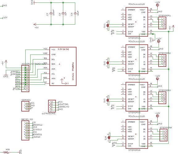
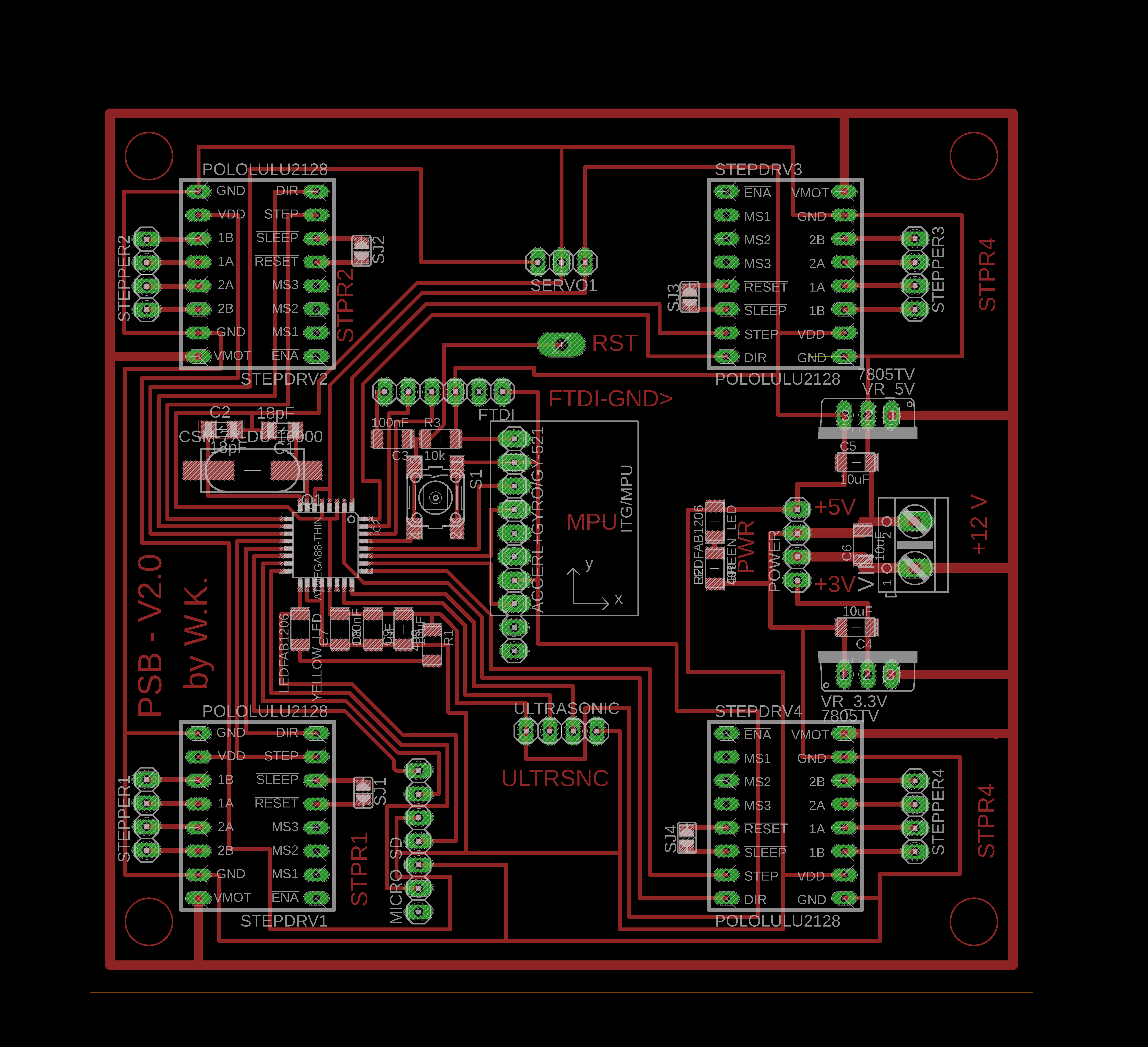
Designing My Board Sketch
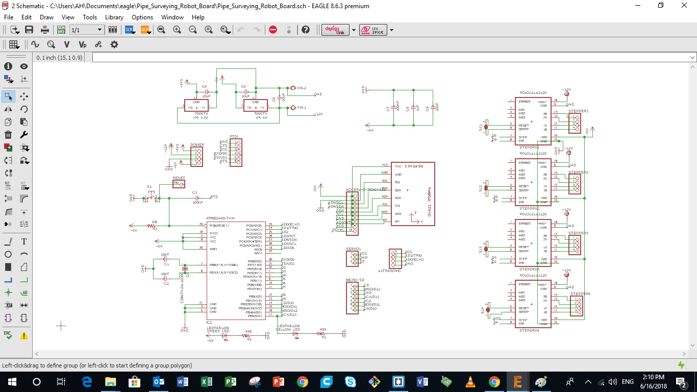
Next i need to design the sketch for the control board of my pipe surveying robot i am building. Many points had to be taken into consideration while designing the board, mainly the Architecture of the Microcontroller i am using, the pin connection to the sensors and outputs i am using. The different parts of the Control board are described in details below.
The image represents the different part of the full control board such as:
- Microcontroller
- Power and Input Pins
- Inputs and Output Pins
- Power Board
- Polulu A4988 Pins
- Nema 17 Stepper Motor Pins
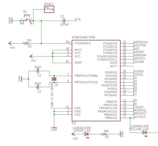
4 a - Microcontroller Connections
In my board, i will be using the ATmega328/P, which is the same Microcontroller used on the Arduino UNO board.
Saying that, and based on the data sheet, other than the Analog and Digital pins, the following connections were made:
- RESET connections. The Reset pin on the microcontroller will be connected to the Reset Pin of the ISP, and that of the FTDI, plus to a push button to be able to Reset the microcontroller whenever i want.
- XTAL1 and XTAL2 pins that will be connected to the external clock, in our case a Crystal having a frequency of 16000 mhz
- Debugging LED, that is connected to the SCK (Arduino pin13) which is mainly used for debuggining
- Power LED, that is connected in parallel to the input 5V Vcc.
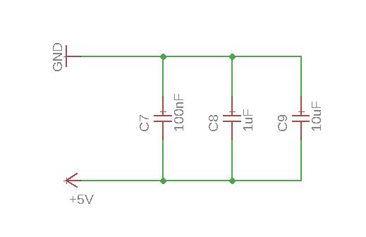
- Decoupling Capacitors, that are connected in paraller to the +5V input, to regulate the voltage and current recieved by the microcontroller, and achieve a stable power supply. More details on how to calculate the Decoupling capacitors can be found on this link
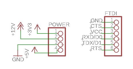
4 b - Power and Input Pins
The main Input Pin headers that i will be using for my board are mainly the following:
- Power Pins that will have a 3.3V and 5V power source, a GND pin and a Vin pin.
- FTDI pins that are used to connect the board to the computer using an FTDI cable
4 c - Inputs and Outputs Pins
A set of pin headers was prepared for the Inputs and Outputs that will be used in my system and connected to the Microcontroller i am using.
Each pin head will have a Vcc pin and a GND pin, plus a number of dedicated Analog or Digital pins.
Among those pin headers are the following:
- Ultrasonic Distance Sensor Pin Headers: I will be using the Ultrasonic Sensor. The pins chosen on the micro-controller are Analog Pins that could be also used as digital inputs or outputs.
- Gyro and Accelerometer Pin Headers: The Accerlometer has 10 pins. So i will prepare a pin header that has pins, that will be mainly used to support the sensor flat paraller to the board. However, only Five pins will be connected to the microcontroller, the VCC and GND plus the SCL and SDA pins on the microcontroller.
- Servo Motor Pin Header: The servo has 3 pins.
- Micro SD Transflash Pin Header: The servo has 7 pins.
- Servo Motor Pin Header: The servo has 3 pins.
- Polulu Pin Header: The servo has 16 pins, devided into two parallel 8 pin headers.
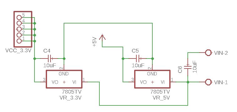
4 d - Power Board
My board will have one battery as a power source dew to the limtied and tight space. Thus i will need power regulators that will achieve having a 12V, 5 V and 3.3 V power supplies on the board. Saying that a power regulation circuit was added to the board to achieved that.
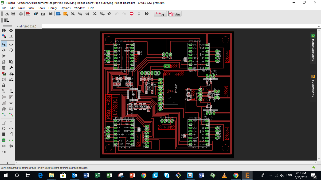
Finalizing Board Layout and Extracting Images
After finalizing the Sketch of my board, the next step is to design the board layout, taking into consideration all the points i mentioned above.
The image represents the layout of the different part of my board such as:
- Microcontroller
- MPU 9250 Pins
- FTDI Pins
- UltraSonic Pins
- Servo Pins
- Polulu A4988 Pins
- Nema 17 Stepper Motor Pins
- Power Pins
- Reset Pin
- Power Board
- V12 Input Pins
You can download the original Eagle design from the following links: My Board
Some Design Details
Various points has been taken into consideration while designing the board layout.
- The stepper motor pins along with the stepper motor driver pins are located at the corners of the board, to make the connection of the motors to the board much easier
- The servo pins and the ultrasonic pins are at the center line of the board, which will give us some freedom when assembling, as they are the last parts to be plugged in
- The MPU pins are located in a way that the MPU-9250 module is centered on the whole board. Thus the chip on the MPU module is centered in the robot for higher accuracy
- The reset pin is used because i did not use a ISP pinout. I will be using the Micro Sd pins to burn bootloader
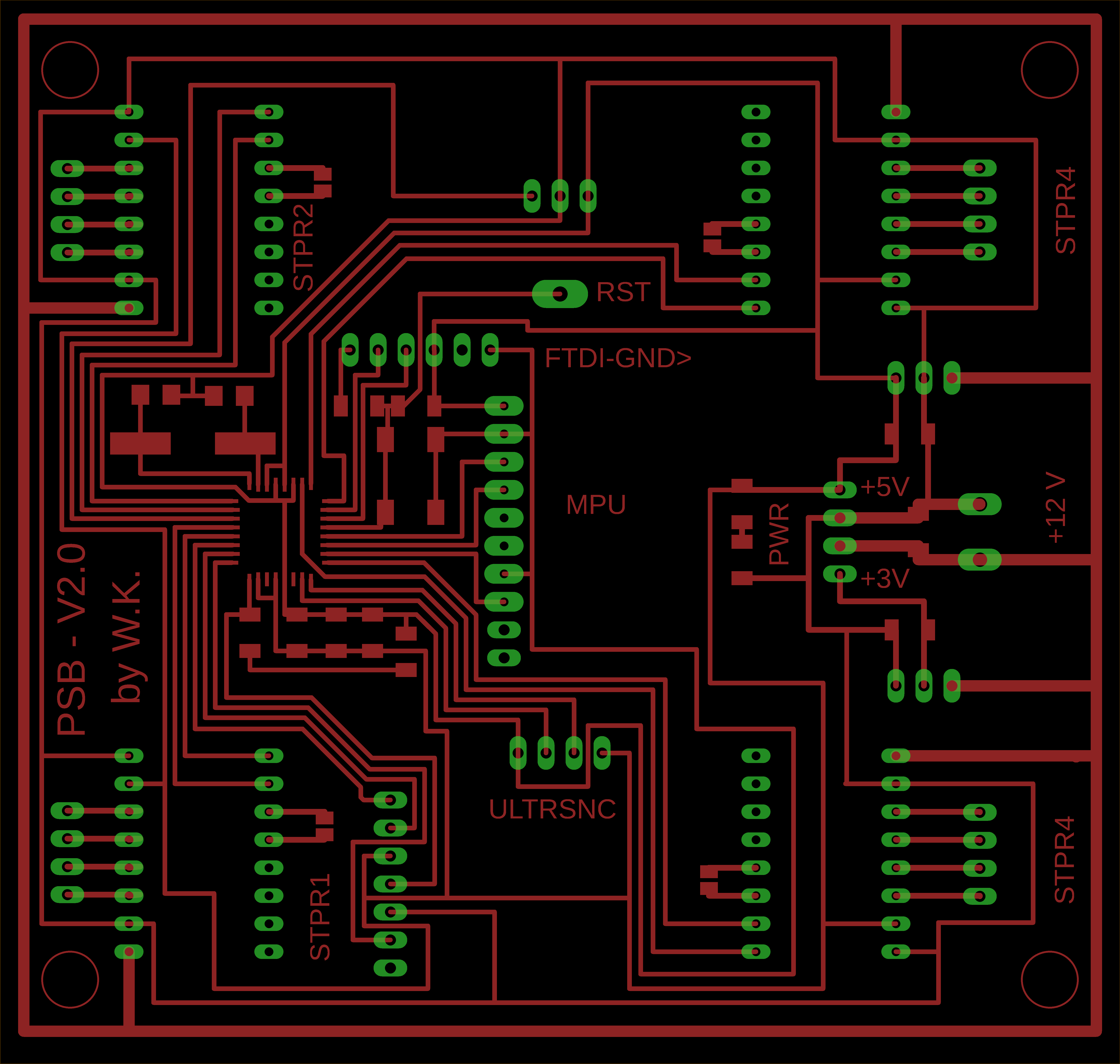
Extracting the Board Layout Images
After finalizing the layout of the PCB on Eagle, we want to extract the image that represents the PCB design. To do so we need to follow the following steps.
- First we turn off all layers by following the following path "view" > "layer settings" > "select none"
- Next we turn on only the layers we want to appear, mainly the ones we need to stay on the copper board during the milling process
- Extract the image in a Monocrome form
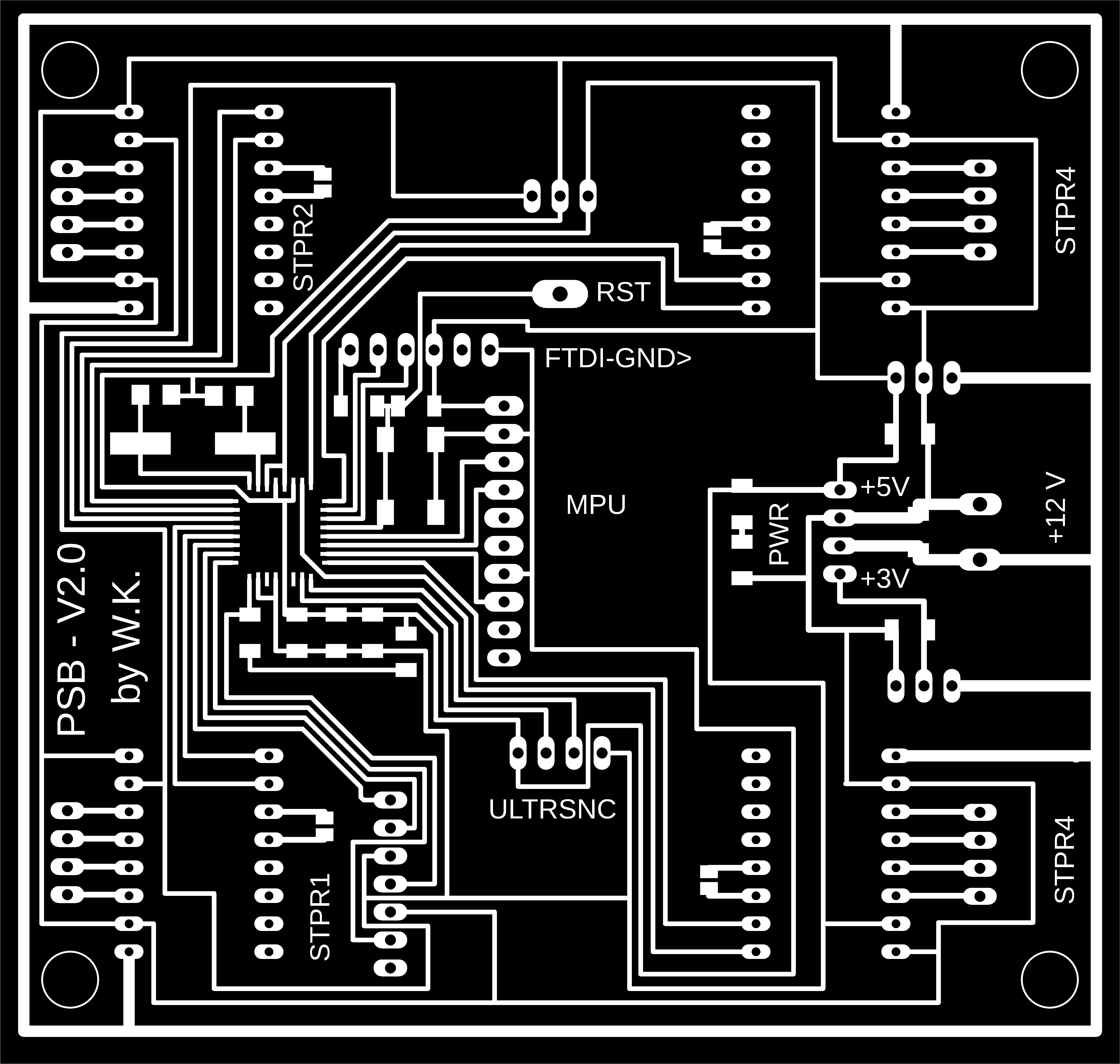
Producing Images on GIMP to be Used for Preparing the G-codes
So the next step after extracting the image from Eagle is to produce the images we need to use on Fab Modules to generate the g-code later.
So first we open the original image from Eagle and "extract as" a new copy that you can edit.
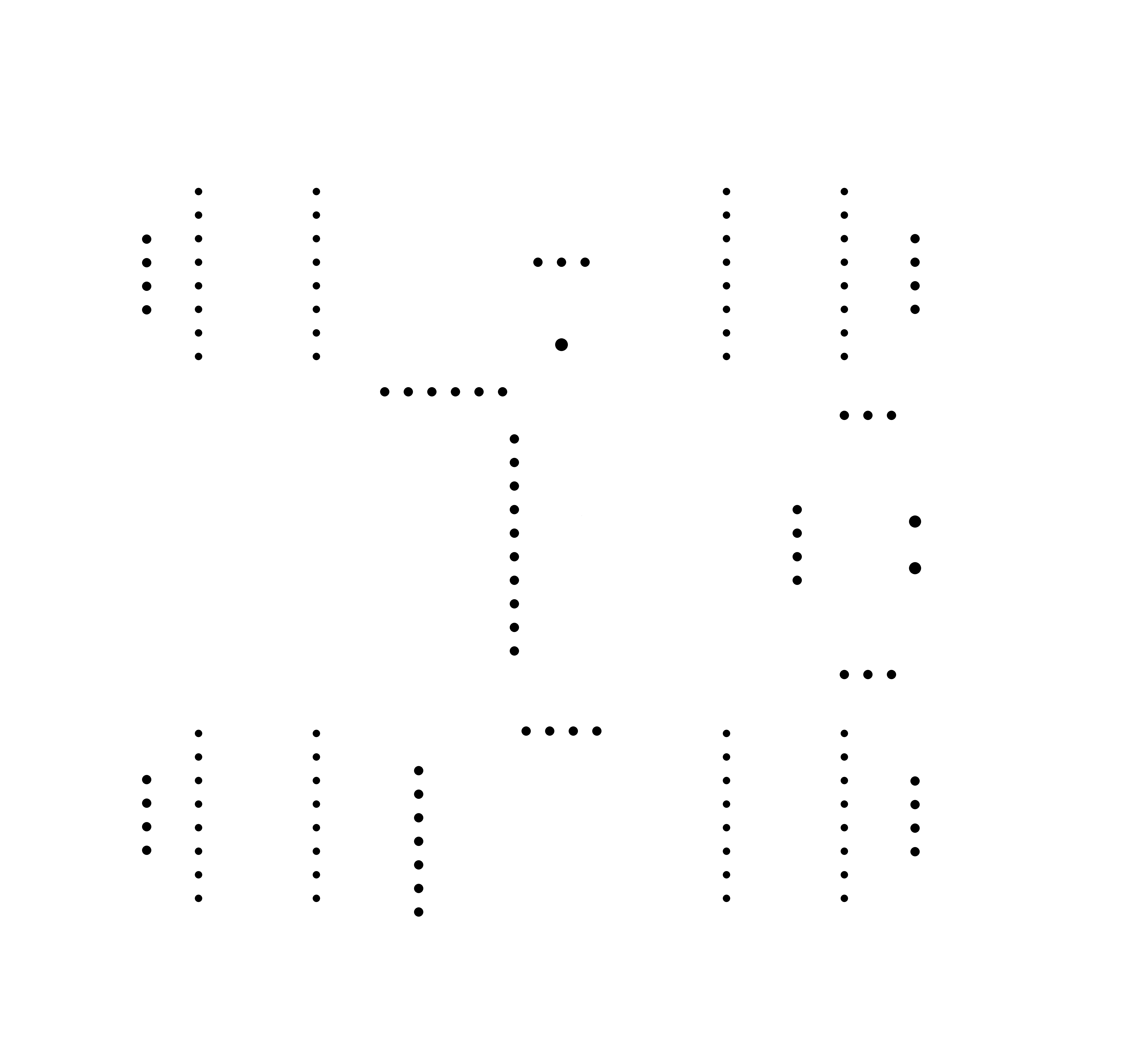
Using GIMP is easy, just fill the area you dont want with black and that's it. I produced 3 images to be used in fab modules. The images are the following:
- Internal Path represents the internal path of the PCB
- Drilling Positions represents the drilling positions of the PCB
- External Path represents the internal path of the PCB
