Designing all the Robot Mechanical Parts
Among those mechanical parts are the following:
- Robot Wheels the will provide the robot will the required motion
- Main Frame That will carry the board, the battery, the servo and all other components
- Left Frame that will carry the left stepper motors
- Right Frame that will carry the right stepper motors
- Stepper Motor Base that will hold the stepper motor in place
- Ultrasonic Sensor Box that will carry the ultra sonic sensor in it and will be fixed on top of the servo motor
- Robot Hull that will mainly cover all internal components, the battery and the wiring
- Battery Base that will cary the battery on top of the board inside the robot hull
Software Used
The following software were used for 2D Vector Design in this week's assignment:- Fusion 360 was used for 3d modelling in this assignment.
- AutoCad was the main software used for 2D design. I used it to design the Press-Fit Kit.
Mechanical Design
The 3d model of our project was built on Fusion 360, mainly because you can build the different components and assemble them together on the software. The various parts that were designed are shown in the attached 3 model.
The full process of the design is shown in the video below.
You can download the original Fusion 360 design from the following Link
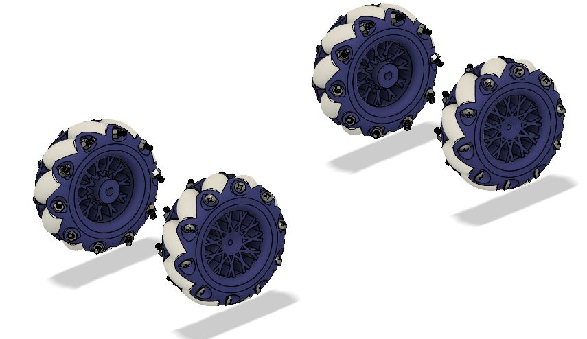
Mecanum Wheels
In my design, i wanted wheels that would achieve easy motion inside the pipe. However, dew to the error caused by the rotation of the robot inside the pipe, using normal wheels means that calibrating the postion of the robot in the pipe is very hard to achieve without designing a very complicated mechanism, along with related code.
Saying that, idecied to use mecanum wheels in my robot, that will give it the caability to move in various directions on various axis, using the same wheel, just by controlling the rotational dirction of each wheel individually.
Thus, i had to design mecanum wheels that would fit on the shaft of Nema 17 stepper motors i will be using.
You can download the original STL files used for the mecanum wheel parts from the following links:
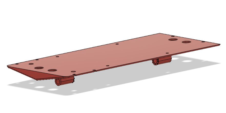
Main Frame
The main frame is the part that will carry all the main comonents of the robot, mainly the control board, with all realted inputs and outputs
Note that the boad position is located at the center of the main frame. And ont he board, the MPU-9350 is cetered at the diagonals of the board. Thus when the board is assembled on top of the main frame using spacers, the MPU-9250 will be located at exactly rhe center of the whole robot. THis would achieve a higher precision while measuring angular gyro data.
You can download the original files used for machining from the following link Main Frame
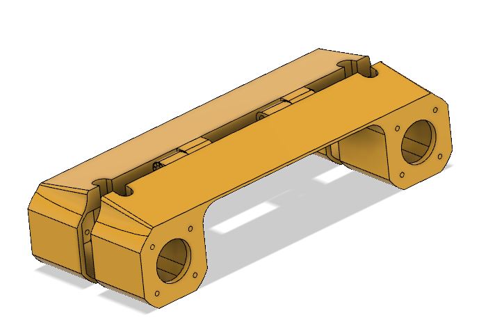
Left and Right Frame
Those parts are assembled to the main frame, and they mainly carry the weight of everything on top of the main frame.
In thos parts, 4 stepper motors Nema 17 will be installed, that will provide motion to the robot.
You can download the original files used for our tests from the following links:
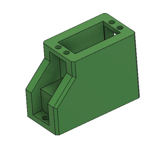
Servo Stand
This part is the part that will be fixed to the main frame using nuts and bolts, and respectively, the servo motor will be fixed onto it. The design took into consideration the wiring of the robot electric parts, thus a wire passage for the wires coming from the stepper motors below it was designed, which will lead directly to the board.
You can download the original files used for machining from the following link Servo Stand
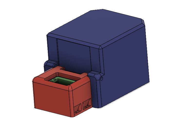
Robot Hull
The robot hull is the part that covers all the components inside the robot including the board,the battery, and all other electronic components connecting to PCB.
The hull was devided into two parts:
- The servo cover, that cover the servo stand with the servo wires, and is fixed to the main frame using bolts. THis part also hashinges tat where the main cover will be attached
- The Main cover that will cver all main components, and will be attached to the servo cover and fixed to the main frame by using nuts and bolts.
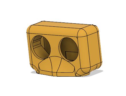
UltraSonic Cover
This part is the part that will carry the Ultra Sonic sensor inside, and will b fixed to the servo motor, thus forming a scanner that will scan the distances around out once it meets an obstacle.
You can download the original files used for our tests from the following links:
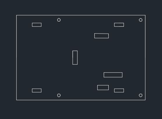
Battery Base
This part is mainly the plate that will be fixed on top of the PCB, and where the battery will be fixed.
Because this part is mainly 2d, the design was made on autocad, to be later laser cut.
You can download the original files used for our tests from the following Link

This work is licensed under a Creative Commons Attribution 4.0 International License