Building the Robots's Board
In this section, i will describe the various steps i followed to build my board.
Machines Used
The main machines and equipment used in this week's assignment are machines that are usually used to produce any PCB. The list of machines we used are the following:- Roland MDX-40 is the Desktop CNC machine used to mill copper boards.
- Tektonix TBS 1052B is the oscilloscope used to observe the operation of the microcontroller circuit board.
- FLUKE 179 was the multimeter used throughout all the process.
- ProsKit SS 207 was the soldering iron used for welding the components.
Software Used
The following software were used in this week's assignment:- Eagle was used to design the PCB.
- GIMP was used to extract and enhance the image of the PCB design.
- Fab Module was the main online platform used to produce the g-code used by the CNC machine.
- Arduino IDE was used to write the code and upload the code.
Preparing the G-Code
Using Fab Modules
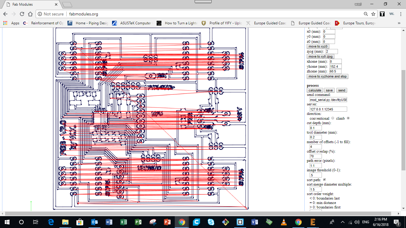
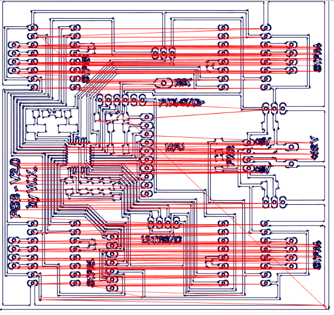
After extracting all images that represent the internal and external paths of the milling bit, it's time now to produce the g-code. I used Fab Modules to produce the g-code for PCB milling on the Roland MDX-40.
The following steps were followed on Fab Modules to generate the g-code:
- Choose input format and select image (png) that the g-code is going to be generated from
- Then select the file from the specific folder
- Then go on to Output format and select the format that applies to the CNC machine you are using, in our case it was Roland mill (.rml)
- Then select Process and choose PCB traces (1/64) for internal paths and drilling and PCB Outline (1/32) for the external parameter
- Then under Output, select the CNC machine you are using, it was a Roland MDX-40. Change the X0, Y0 and Z0 to save space on copper board used. Then check the Feed Speed. I was using 4mm/sec for the Internal Traces and 0.5mm/sec to the External Parameter and Drilling
- Then Under Process, adjust the cut depth which should be 0.0 mm for the internal tracing, and 1.7mm for the external parameter and drilling. The tool diameter (milling bit) which was 0.1 mm for the internal traces, 1 mm for the external parameter, and 0.8 mm for drilling.
The Number of offsets used was 4. The offset overlap used was 70%
No other adjustments were be made. - Once the Input, Output, and Process tabs are double have been adjusted and double checked. Go ahead and press the Calculate button
- Then finally click the Save button and save it to the designated folder. It would be saved as an .rml file
Building My New PCB and Programming it
In order to produce the PCB that willbe controlling my robot, the following steps were followed:
- CNC Milling the Copper Board
- Soldering All Components
- Downloading Firmware
1 - CNC Milling the Copper Board
After preparing the G-code, the following steps were taken to mill the layout onto the copper board:
- First I needed a software that would send the g-code directly to the Roland MDX-40. In my case I used the Drop-Out software to send the .rml file to the CNC machine
- On the Drop-Out application press the add button and choose the .rml file you created and press open
- Then go to File and select Print Setup
- On the Print setup first choose the name of your printer, in my case it was the Roland TS-30
- Then go to Properties and press the Tool tab, the only thing that should be adjusted are the Z down position and Z engraving pitch both should be at 0.00 mm. During the milling the RPM used was 10,000 for all jobs
- Then go on to the Options tab and select Operation Panel
- Set the X and Y-axis on the position where you want your PCB to be engraved on the copper board inside the CNC, then press the XY axis SET button
- As for the Z-axis, we needed to zero the tool at the top surface of the copper board. In order to do this delicate process we need to gradually bring it down onto the board, with the help of a multimeter with the beep mode on and have one of the cables on the copper board and the other on the drilling bit. In this case as soon as the drill-bit touches the copper board the multimeter would beep. Make sure to go extremely slow at the end so you dont risk breaking your drill-bit
- Once the beep is heard, you know that the drilling bit is right at the surface and you can go back to the operational panel (on Drop-out), select the Z-axis from the dropdown menu and set the Z-axis.
- Once everything is set press OK until you reach the first page of drop-out and press theOutputbutton. Your CNC machine should now start the process of milling/engraving the copper plate set inside. watch the process until its done
- Check the final result, using a multimeter with the beep setting to make sure components are isolated and all conductivity channels are connected
2 - Soldering All Components
Now that we have the PCB layout cut-out, the next step is to start soldering. In order to do so we first need certain tools to proceed, find the list with specs below:
- Soldering Iron: set at 320 degrees celcius
- Solder wire: 0.5 mm
- Tweezers
- Desoldering copper
- Vacuum
- Tack-it
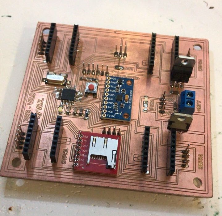
The following list represents the list of components used in Board:
- ATmega328/P
- 1 x 16 MHz Crystal
- 2 x 22pF Capacitor
- 2 x 10uF Capacitor
- 1 x 1uF Capacitor
- 2 x 100pF Capacitor
- 3 x 10 Kohm Resistor
- 2 x 499 ohm Resistor
- 1 x White LED
- 1 x Green LED
- 1 x 4-pin push button
- 1 x 6-pin FTDI pin headers
- 6 x 4-pin headers Male
- 1 x 7-pin headers Male
- 1 x 10-pin headers Male
- 1 x 3-pin headers Male
- 8 x 8-pin headers Male
- 5v and 3V Voltage regulator
For the final step in this process, make sure all connections are ok using the multimeter on the beep option. And you should be set to move on to the next step.
.jpeg)
3 - Downloading Firmware
After finalizing the code, the next step is to upload the firmware to the newly constructed Board. To do that, we have to set first the Arduino Board as an ISP and follow the following steps :.
- Choose the Board as "Arduino/Genuino Uno" by going to "tools" > "board" > "Arduino/Genuino Uno"
- Next choose the port where the Arduino is connected
- Then follow the following "file" > "exaples" > "ArduinoISP" to open the Arduino ISP code
- Next upload the code to the Arduino Board
After setting the Arduino board as an ISP, the next step is to push the code to My Board
To do so, first connect the Arduino Board to the new Board following those connections:
- 5V to Vcc
- GND to GND
- 10 to Reset
- 11 to MOSI
- 12 to MISO
- 13 to SCK
- Choose the Arduino/Genuino UNO board
- Choose the terminal that the Arduino is connected to, usually a COM and a Number
- Burn Bootloader by pressing "tools" > "Burn Bootloader"
