Robot Parts Production
Machines Used
The main machines used in this week's assignment are the 3d printers, the Laser Cutter and the Vinyl Cutter.- Ultimaker 3 and Ultimaker 3 Extended is one type of the FDM 3d printers. It was used for 3d printing small scale objects up to 20x20x30 cm.
- DeltaWASP 4070 is one of the FDM 3d printers. It was used for 3d printing larger scale objects up to 40x40x70 cm.
- Form 2 is our SLA 3d Printer. It was used for high-resolution prints and complicated designs that are hard to achieve on the Ultimakers.
- Epilog Fusion M2 120 Watts was used for laser engraving and laser cutting in this assignment. This Epilog Fusion M2 uses the CO2 Laser Technology to cut and engrave. The laser source is guidged by 2 axis (X and Y) that guide the focal point of the laser where cutting will occur.
Software Used
The following software were used for 2D Vector Design in this week's assignment:- Fusion 360 was used for 3d modelling in this assignment.
- CorelDraw was used to make fast 2D designs mainly for testing the different capabilities of the Laser Cutter. It is an easy software that could be used for color mapping.
- AutoCad was the main software used for 2D design. I used it to design the Press-Fit Kit.
Production
After preparing the 3d design of the Pipe Surveyin Bot, the next step was to start manufacturing the different parts. Each part was produced using a different technology available in the lab, to achieve the best final product.
The main digital fabrication tools that were used in this project was the following:
- Ultimaker FDM 3d Printer
- DeltaWASP 4070 FDM 3d Printer
- Form 2 SLA 3d printer
- Epilog Laser Cutter
Mecanum Wheels - SLA 3d Printing
The mecanum wheels had a lot of details and curvy shapes. Saying that, achieving the final product i had in mind would be hard if i used traditional FDM 3d printing.
Thus to get a seemless mecanum wheel, i decided to print it using the SLA 3d Printer we have in the lab.
I printed the mecanum wheels using the Form 2 SLA 3d printer. I chose Tough Resin material to print them and they ended out to look great and function great.
In addition to that, i printed the rollers using normal PLA on the Ultimaker. They looked really nice, but they did not achieve the wanted frinction needed to prevent slippage.
You can download the original STL files used for 3d printing the mecanum from the following link
Frames and Hull - FDM 3d Printing
Most of the Pipe Surveying Bot parts were 3d printed using FDM technology. I used the DeltaWASP 4070 for printing the Main Frame, the Left and the Right frame. I also used the Ultimakers to print the Servo Stand, UltrSonic Sensor coverand the Covers.
The video below shows how the different parts were produced and how they ended out.
I used PLA to print all the parts but with various colors.
- Red PLA
- Blue PLA
- Yellow PLA
Battery Base - Laser Cutting
The battey base was mainly a flat sheet that will be fixed on the spacers, above the PCB,inside the Robot's Hull.
Thus to make the plate, I chose Laser Cutting as it is a fast, precise and very efficient tools to use.
The video below represents how this plate was produced and were it was fixed inside the robot.
You can download the original autocad file used from the following links:
Battery Base
Assembling the Pipe Surveying Robot
After producing all the different parts using the different technologies, the next step is to assemble all parts together to make a functional robot.
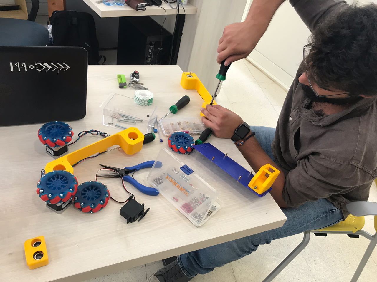
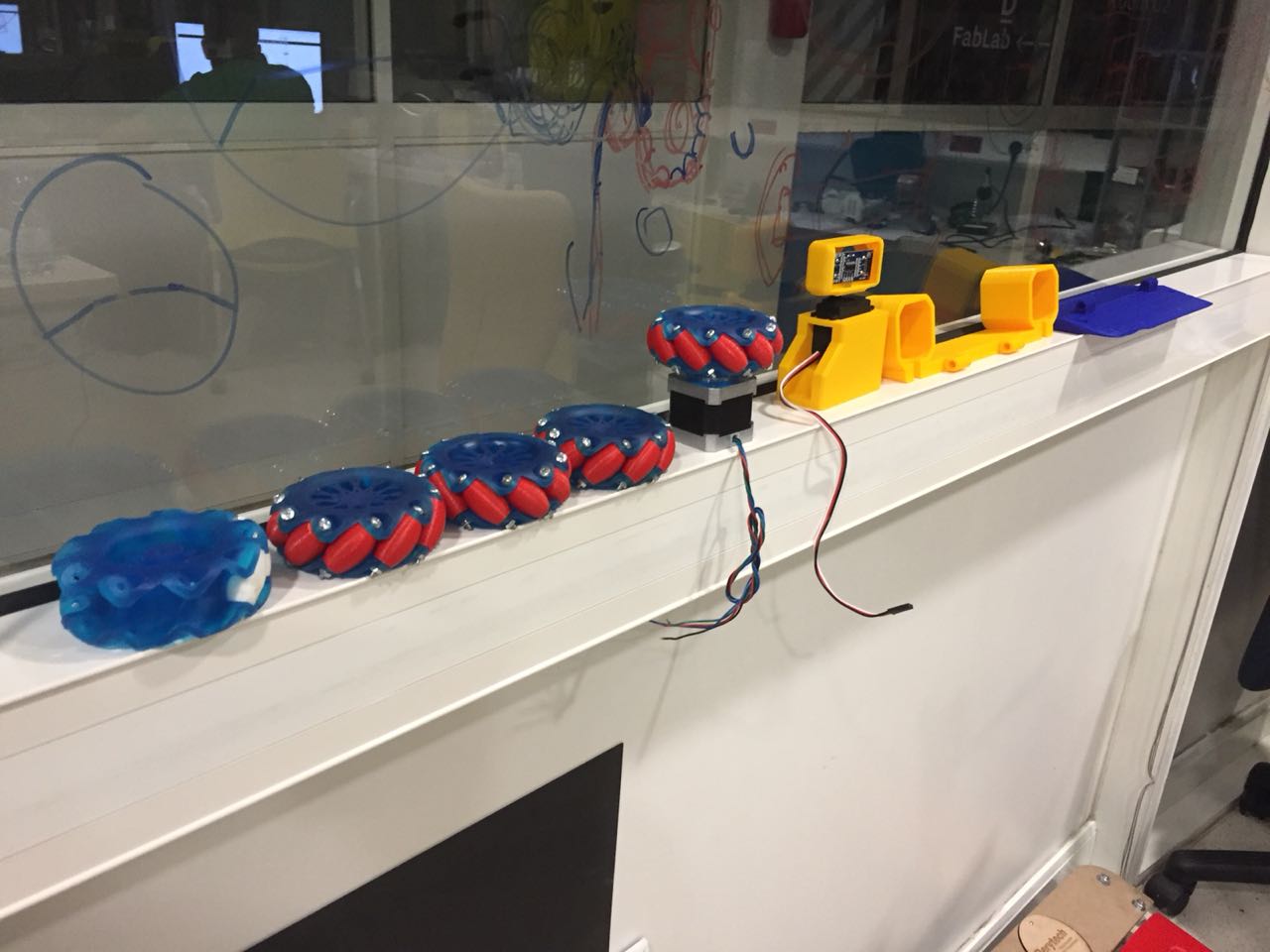
Preparing all parts
After producing all parts, the first step before final assembly is to assemble the small parts together. I started by assembling the Mecanum Wheels and testing if they fit on the Nema 17 shaft and if they rotate correctly.
So the mecanum wheels worked perfectly, with the help of some oil i usually use for lubricating 3d printed. After that i prapared all the parts in preparation to the next step which is checking if the parts fit together.
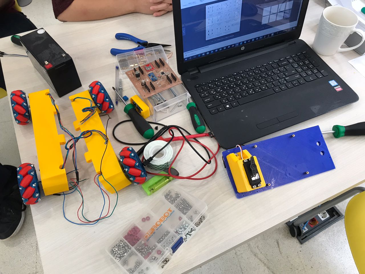
Assembling the Individual Parts
Before final assembly of the robot parts, i wanted to make sure that they all fit together, in order to make final edits before assembling. All the different parts were assembled and tested together, to make sure that they will achieve the job they are meant to do.
The Stepper motors fit perfectly in the Left and Right Frame. The holes that were use to pass the stepper motor wires to the board through the main frame looked great. The duct made for the front stepper motor wires also were as expected.
Thus all parts fitted perfectly together, but the connection between the Main Frame, the Right Frame and the Left Frame had one design error. I didn't take into consideration the size of the tool that will be used to tighten the bolt. Thus tighting the bolt was a hard job.
Wiring
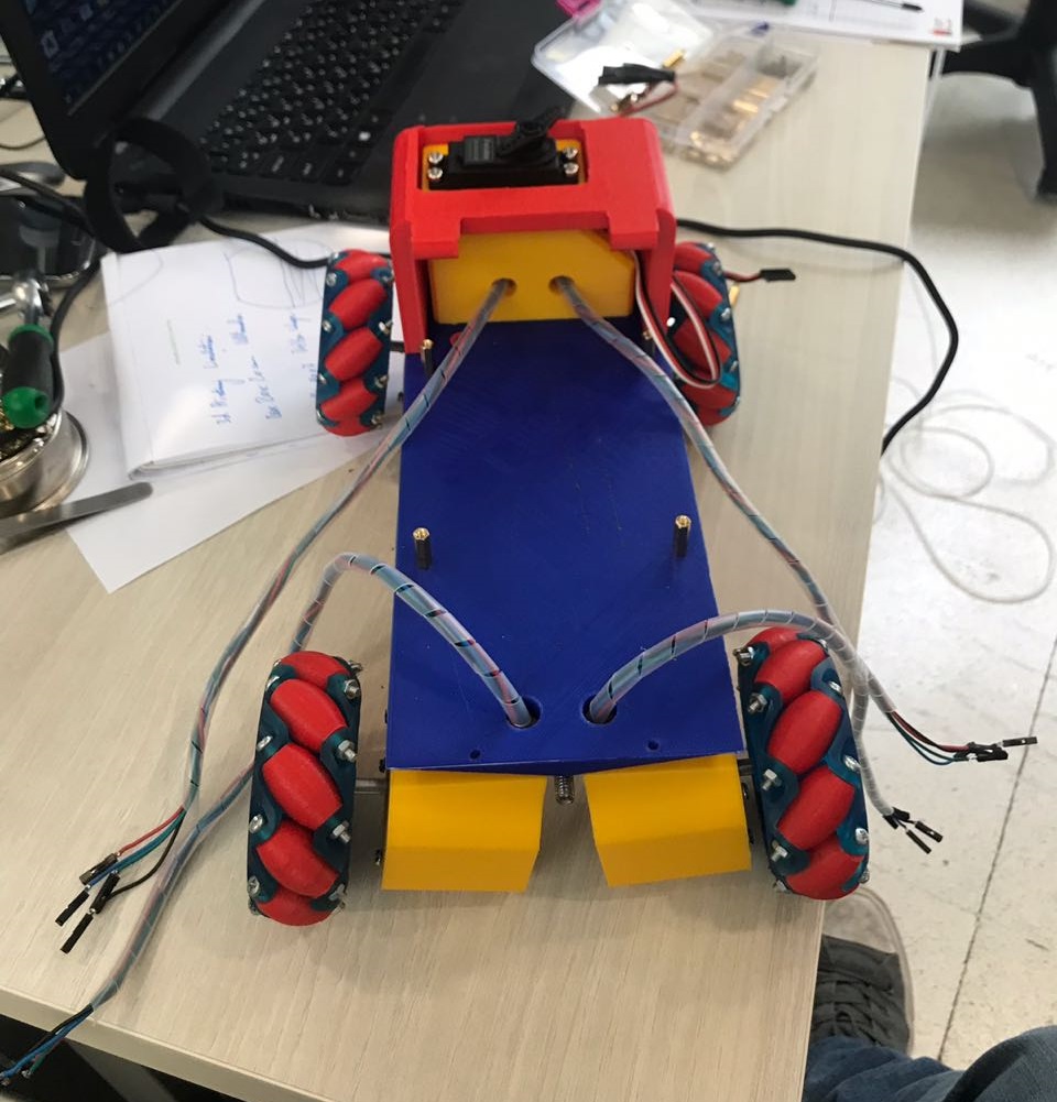
After fixing the 4 stepper motors and the servo motor on the main frame, the next step was to pass the wires in preperation to be insterted on the control board that will be installed later. Thus the wires were pulled through the holes and ducts that were designed for this reason.
After that, the stepper motor wires were grouped in side a flexible wiring conduit, to prevent them tangling with other wires. Thus in the end, as shown in the image, all groups of wires were grouped together, in preperation to be plugged in the PCB when installed.
Final Assembly
After making sure that all individual components work as they are meant to do, the next step is to make the full assembly and check if all works out together.
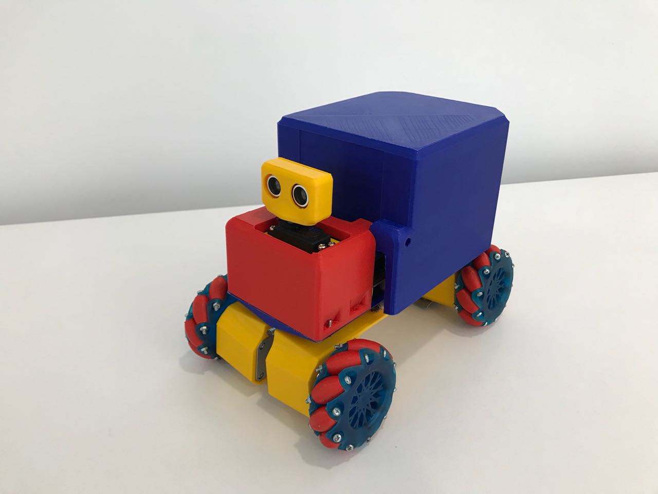
After assembling all parts, the Pipe Surveying Bot looked perfect, exactly the same as the Fusion 360 design, thanks to the 3d Printing Technology. For now the robot does not look like a robot, but more like a toy. But it do function like a robot, made of plastic.
Testing the Robot's Mechanism
After assembling all parts of the robot, and making sure that each part does its specific job, the next step was to make sure that the whole system works correctly all together before installing the electronic components and working on the control part.
The video below shows how the system worked by moving it manually by hand. The robot moved in all directions as expected by the help of the mecanum wheels. The next step is to start controlling it and checking if it works for real.
