Back to Final Project Main Page - PSB

Testing the PCB and the Various Robot Functionalitiy

Testing the Robot's Capabilities


After finalizing the production of the control board and assembling all the mechanical components of the robot, it is time now to test the various inputs and outputs with the board. Adding to that, I wanted to test the various capabilities of the Pipe Surveying Robot.


Software Used

The following software were used in this week's assignment:
  1. Eagle
  2. was used to design the PCB.
  3. Arduino IDE
  4. was used to write the code and upload the code.


Testing My Board with Inputs and Outputs


Testing

After burning the bootloader, the next step is to test the various inputs and outputs using the newly constructed board.
But first, i wanted to make sure that my board really works before testing the inputs and outputs.
So in the beginning, I performed various test to check if my board is working, and then to check if i can successfully recieve data from my inputs and issue and save data on my outputs.

You can download the test file from the following link: Serial Test This code tests if the board works and sends data to the serial monitor
Next i tested the board using the very famous Blink code.
After that, i tested all the inputs and outputs of the board.

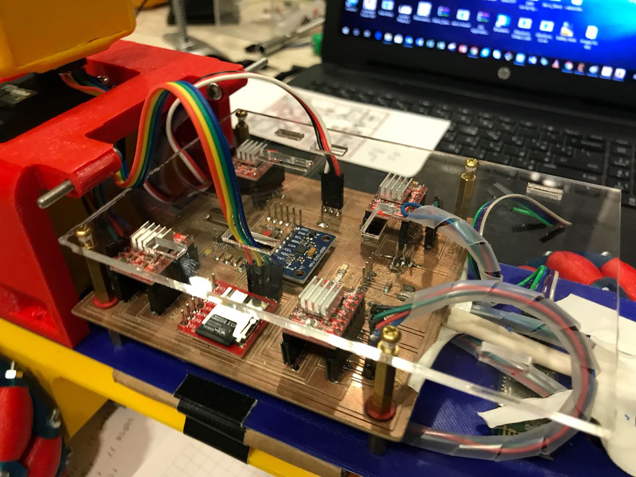
To program the board, I used an FTDI cable through the FTDI pin found on my board. As shown in the image above, the Ground pin is labeled on the board. The following process is usually followed to upload the code on the Board.
  1. Compile the code and check for any bugs
  2. Choose the baord as Arduino/Genuino Board from the "tools" drop down menue
  3. Choose the Port related to the board
  4. Upload the code to the baord using the "Upload" button

1 - Stepper Motor

In order to control a stepper motor, a Stepper Motor Driver is required which will recieve two signals from the microcontroller in addition to two power supplies, one coming from the Control Board and the other is the Voltage Needed to power the Stepper Motors.
Each stepper motor driver has the following connections

  1. Reset pin which is connected to the 5V power source, either from the Arduino Board, or any other board
  2. Sleep pin which is also connected to the 5V power source, either from the Arduino Board, or any other board
  3. Step pin which is connected to a digital pin which will be set as an output pin and control the direction of the rotation
  4. Dir pin which is connected to a digital pin that is set to be an output and control the steps of the motor
  5. GND pin which is connected to the GND of the power source or board you are using
  6. VMOT pin that is connected to the positiove poleof the motor power supply
  7. GND that is connected to the GND of the motor power supply
  8. B2, B1, A1, and A2, that are the output pins going towards the stepper motor.
So a Four-Pin connection will be needed on My Board for the Plolulu A4988 stepper motor driver. You can check the full details of the Plolulu A4988 stepper motor driver by visiting the following link link

In order to test all stepper motors, i used a code that drives all motors together, once the board has voltage on it.

Below is the code used to test the movement of the four stepper motors
/* Simple Stepper Motor Control Exaple Code #include <AccelStepper.h> // Define some steppers and the pins the will use AccelStepper stepper1(1, 8, 9); // Defaults to AccelStepper::FULL4WIRE (4 pins) on 2, 3, 4, 5 AccelStepper stepper2(1, 5, 6); // Defaults to AccelStepper::FULL4WIRE (4 pins) on 2, 3, 4, 5 AccelStepper stepper3(1, 3, 2); // Defaults to AccelStepper::FULL4WIRE (4 pins) on 2, 3, 4, 5 AccelStepper stepper4(1, A2, 4); // Defaults to AccelStepper::FULL4WIRE (4 pins) on 2, 3, 4, 5 void setup() { stepper1.setMaxSpeed(200.0); stepper1.setAcceleration(100.0); stepper2.setMaxSpeed(200.0); stepper2.setAcceleration(100.0); stepper3.setMaxSpeed(200.0); stepper3.setAcceleration(100.0); stepper4.setMaxSpeed(200.0); stepper4.setAcceleration(100.0); stepper1.moveTo(20000); stepper2.moveTo(20000); stepper3.moveTo(20000); stepper4.moveTo(20000); } void loop() { stepper1.run(); stepper2.run(); stepper3.run(); stepper4.run(); } Testing was done using My Board after it was constructed. The Video shows the test done.
You can download the original Arduino Code Used from the following Link
s

2 - Servo Motor

The Servo motor is maily used to produce a controlled angular motion. The servo motor is connected to the control board using 3 pins:

  1. Vcc which is connected to the 5V power supply from the board
  2. GND which is connected to the GND pin on the control board
  3. Signal pin which is the output pin that controls the motion of the servo
Saying that, The Stepper Motor requires a 3-pin connector at the control board.

To test the servo motor, i used the example code found in the Arduin IDE.
Below is the code used to control a servo motor
Servo myservo; // create servo object to control a servo // twelve servo objects can be created on most boards int pos = 0; // variable to store the servo position void setup() { myservo.attach(9); // attaches the servo on pin 9 to the servo object } void loop() { for (pos = 0; pos = 180; pos += 1) { // goes from 0 degrees to 180 degrees // in steps of 1 degree myservo.write(pos); // tell servo to go to position in variable 'pos' delay(15); // waits 15ms for the servo to reach the position } for (pos = 180; pos >= 0; pos -= 1) { // goes from 180 degrees to 0 degrees myservo.write(pos); // tell servo to go to position in variable 'pos' delay(15); // waits 15ms for the servo to reach the position } } Testing was done using My Board after it was constructed. The Video shows the test done.
You can download the original Arduino Code Used from the following Link


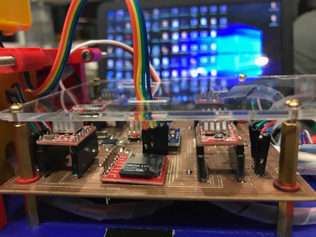
3 - microSD Transflash Breakout

The main tool i will be using to save the data collected by the robot is the microSD Transflash Breakout.
Breakout board for the microSD socket that is not much bigger than your fingernail. Compatible with the SPI interface found on any SD card, this tiny form factor was created for cell phone storage and is perfect for your next MP3 project! Board comes fully assembled and tested.

The microSD Transflash Breakout has 7 pins:

  1. Vcc that could be connected to a 5V or 3.3V power suply.
  2. GNG pin which is connected to the GND of the control board
  3. SCK which has to be connected to SCK pin of the micro controller, known by the Analog 5 pin on the Arduino Board
  4. D0 pin which has to be connected to the MISO pin of the microcontroller.
  5. DI pin which has to be connected to the MOSI pin of the microcontroller.
  6. CS pin which is connected to a digital pin.
  7. CD pin which is connected to a digital pin.


You can check the full details of the SparkFun microSD Transflash Breakout by visiting the following link SparkFun microSD Transflash Breakout

Below is the code used to save data on the micro sd
#include <SPI.h> #include <SD.h> File myFile; void setup() { // Open serial communications and wait for port to open: Serial.begin(9600); while (!Serial) { ; // wait for serial port to connect. Needed for native USB port only } Serial.print("Initializing SD card..."); if (!SD.begin(10)) { Serial.println("initialization failed!"); while (1); } Serial.println("initialization done."); // open the file. note that only one file can be open at a time, // so you have to close this one before opening another. myFile = SD.open("test.txt", FILE_WRITE); // if the file opened okay, write to it: if (myFile) { Serial.print("Writing to test.txt..."); myFile.println("testing 1, 2, 3."); // close the file: myFile.close(); Serial.println("done."); } else { // if the file didn't open, print an error: Serial.println("error opening test.txt"); } // re-open the file for reading: myFile = SD.open("test.txt"); if (myFile) { Serial.println("test.txt:"); // read from the file until there's nothing else in it: while (myFile.available()) { Serial.write(myFile.read()); } // close the file: myFile.close(); } else { // if the file didn't open, print an error: Serial.println("error opening test.txt"); } } void loop() { // nothing happens after setup } Unfortunately, i could not take a video of the board saving data on the micro sd, however, i can guarantee that when you insert the MicroSd in a computer, you will see a text file named "test.txt".
You can download the original Arduino Code Used from the following Link
Mecanum Wheels

4 - Ultrasonic Distance Sensor

As mentioned previously, the Ultrasonic Distance Sensor is a Digital Sensor. The HC-SR04 Ultrasonic Sensor Module has four pins:

  1. Vcc which is connected to the 5V power source, either from the Arduino Board, or any other board
  2. Trigger pin which is connected to a digital pin which will be set as an output pin
  3. ECHO pin which is connected to a digital pin that is set to be an Input
  4. GND which is connected to the GND of the power source or board you are using


You can download the data sheet for the Ultrasonic Ranging Module HC-SR04 from the following
  • link
  • Below is the code used to read data from the Ultrasonic Sensor
    // defines pins numbers const int trigPin = A0; const int echoPin = A1; // defines variables long duration; int distance; void setup() { pinMode(trigPin, OUTPUT); // Sets the trigPin as an Output pinMode(echoPin, INPUT); // Sets the echoPin as an Input Serial.begin(9600); // Starts the serial communication } void loop() { // Clears the trigPin digitalWrite(trigPin, LOW); delayMicroseconds(2); // Sets the trigPin on HIGH state for 10 micro seconds digitalWrite(trigPin, HIGH); delayMicroseconds(10); digitalWrite(trigPin, LOW); // Reads the echoPin, returns the sound wave travel time in microseconds duration = pulseIn(echoPin, HIGH); // Calculating the distance distance= duration*0.034/2; // Prints the distance on the Serial Monitor Serial.print("Distance: "); Serial.println(distance); }
    You can download the original Arduino Code Used from the following Link


    Accelerometer and Gyro (MPU-9250)

    The main sesnor i am using in my Pipe Surveying Robot is the the MPU-9250.
    This sensor is used to cllect 9 different values from the 3-Axis Accelerometer, Gyro, & Magnetometer MEMS found on its single chip.

    The module has 10 pins:

    1. Vcc that could be connected to a 5V or 3.3V power suply. The MPU-6050 module has a voltage regulator on board
    2. GNG pin which is connected to the GND of the control board
    3. SCL which has to be connected to SCL pin of the micro controller, known by the Analog 5 pin on the Arduino Board
    4. SDA pin which has to be connected to the SDA pin of the microcontroller, known by the ANalog 4 pin on the Arduino board.
    5. EDA pin
    6. ECL pin
    7. AD0 pin
    8. INT pin is connected to the GND of the control board
    9. NCS pin
    10. FSYNC pin


    You can download the data sheet for the MPU-9250 9-DOF 3-Axis Accelerometer, Gyro, & Magnetometer from the following link

    Below is the code used to read data from the Ultrasonic Sensor
    #include <Wire.h> #include <FaBo9Axis_MPU9250.h> FaBo9Axis fabo_9axis; void setup() { Serial.begin(9600); Serial.println("RESET"); Serial.println(); Serial.println("configuring device."); if (fabo_9axis.begin()) { Serial.println("configured FaBo 9Axis I2C Brick"); } else { Serial.println("device error"); while(1); } } void loop() { float ax,ay,az; float gx,gy,gz; float mx,my,mz; float temp; fabo_9axis.readAccelXYZ(&ax,&ay,&az); fabo_9axis.readGyroXYZ(&gx,&gy,&gz); fabo_9axis.readMagnetXYZ(&mx,&my,&mz); fabo_9axis.readTemperature(&temp); Serial.print("ax: "); Serial.print(ax); Serial.print(" ay: "); Serial.print(ay); Serial.print(" az: "); Serial.println(az); Serial.print("gx: "); Serial.print(gx); Serial.print(" gy: "); Serial.print(gy); Serial.print(" gz: "); Serial.println(gz); Serial.print("mx: "); Serial.print(mx); Serial.print(" my: "); Serial.print(my); Serial.print(" mz: "); Serial.println(mz); Serial.print("temp: "); Serial.println(temp); delay(1000); }
    You can download the original Arduino Code Used from the following Link

    Testing the Robot Functionalities


    Testing

    After making sure that input and output electronic components work individually the next step is to make sure that they achieve the intended robot objectives.

    To do that, i had to test the following main capabilites must be achieved for it to be successful:
    1. Motion in all directions
    2. Capability to detect obstacles and stop
    3. Capability to gather angular and position data
    4. The ability to regulate position according to the measured angular data
    5. Capability to store the data on an external microSD memory card
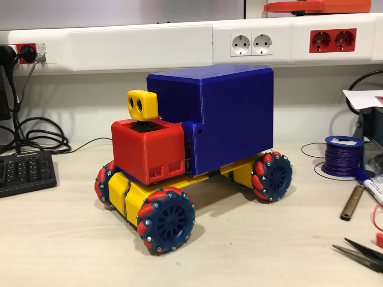
    1 - Testing Motion

    In order to test the movement of my robot, and test the functionality of the mecanum wheels, i prepared an Arduino code that would allow me to control the robot remotely through bluetooth. This code reads from the serial monitor, and accordingly, it performs the motion function previously set.

    To control the robot remotely, i used the following link Arduino Car application on the Android Google PLay as it seemed perfect for the functionalities i had in my project.

    In addition to that, i wanted to build my personal application that has the same functionalities of this application. So i created my remote control app using MIT app Inventor. But it could be the ugliest app you have ever seen, but it does the job. You can download the app from the following link

    Below is the code used to test the movement of the four stepper motors
    // This code controls 4 simultaneous steppers // It reads data from the serial monitor, that is sent through Bluetooth, // and controls the steppers accordingly // THis code runs all steppers at the same time. // // Copyright (C) 2018 Wael Khalil #include <TimerOne.h> //include the library code #include <AccelStepper.h> //stepper motors library //include the library code #include <Servo.h> //servo motor library //Define pins used for the Servo Motor const int ServoPin = 7; Servo myServo; // create servo object to control a servo //define some contant numbers that will be used in the code const int MaxSpeedSlow = 300; const int AccelerationSlow = 100; const int SlowDistance = 10000; bool stopped = true; const int Initialize_Distance = 50; // Define some steppers and the pins they will use AccelStepper stepper1(1, 8, 9); AccelStepper stepper2(1, 5, 6); AccelStepper stepper3(1, 3, 2); AccelStepper stepper4(1, A2, 4); void setup() { pinMode(13,OUTPUT); // initialize serial: Serial.begin(9600); //Define servo pin myServo.attach(7); //initialize servo position myServo.write(90); delay (2000); //set initial stepper settings stepper1.setMaxSpeed(MaxSpeedSlow); stepper1.setAcceleration(AccelerationSlow); stepper2.setMaxSpeed(MaxSpeedSlow); stepper2.setAcceleration(AccelerationSlow); stepper3.setMaxSpeed(MaxSpeedSlow); stepper3.setAcceleration(AccelerationSlow); stepper4.setMaxSpeed(MaxSpeedSlow); stepper4.setAcceleration(AccelerationSlow); Timer1.initialize(250); // set a timer of length 100000 microseconds (or 0.1 sec - or 10Hz => the led will blink 5 times, 5 cycles of on-and-off, per second) Timer1.attachInterrupt( doSteps ); // attach the service routine here //Initialize Robot stepper1.moveTo(-Initialize_Distance); stepper2.moveTo(Initialize_Distance); stepper3.moveTo(Initialize_Distance); stepper4.moveTo(-Initialize_Distance); stepper1.runToPosition(); stepper2.runToPosition(); stepper3.runToPosition(); stepper4.runToPosition(); delay(5000); } void doSteps() { if(stopped == false) { stepper1.runSpeed(); stepper2.runSpeed(); stepper3.runSpeed(); stepper4.runSpeed(); } // Toggle LED digitalWrite( 13, digitalRead( 13 ) ^ 1 ); } void forward() { //set stepper settings stepper1.setSpeed(-MaxSpeedSlow); stepper2.setSpeed(MaxSpeedSlow); stepper3.setSpeed(MaxSpeedSlow); stepper4.setSpeed(-MaxSpeedSlow); } void back() { //set stepper settings stepper1.setSpeed(MaxSpeedSlow); stepper2.setSpeed(-MaxSpeedSlow); stepper3.setSpeed(-MaxSpeedSlow); stepper4.setSpeed(MaxSpeedSlow); } void left() { //set stepper settings stepper1.setSpeed(-MaxSpeedSlow); stepper2.setSpeed(-MaxSpeedSlow); stepper3.setSpeed(MaxSpeedSlow); stepper4.setSpeed(MaxSpeedSlow); } void right() { //set stepper settings stepper1.setSpeed(MaxSpeedSlow); stepper2.setSpeed(MaxSpeedSlow); stepper3.setSpeed(-MaxSpeedSlow); stepper4.setSpeed(-MaxSpeedSlow); } void forwardleft() { //set stepper settings stepper1.setSpeed(-MaxSpeedSlow); stepper2.setSpeed(0); stepper3.setSpeed(MaxSpeedSlow); stepper4.setSpeed(0); } void forwardright() { //set stepper settings stepper1.setSpeed(0); stepper2.setSpeed(MaxSpeedSlow); stepper3.setSpeed(0); stepper4.setSpeed(-MaxSpeedSlow); } void backright() { //set stepper settings stepper1.setSpeed(MaxSpeedSlow); stepper2.setSpeed(0); stepper3.setSpeed(-MaxSpeedSlow); stepper4.setSpeed(0); } void backleft() { //set stepper settings stepper1.setSpeed(0); stepper2.setSpeed(-MaxSpeedSlow); stepper3.setSpeed(0); stepper4.setSpeed(MaxSpeedSlow); } void rotateLeft() { //set stepper settings stepper1.setSpeed(MaxSpeedSlow); stepper2.setSpeed(MaxSpeedSlow); stepper3.setSpeed(MaxSpeedSlow); stepper4.setSpeed(MaxSpeedSlow); } void rotateRight() { //set stepper settings stepper1.setSpeed(-MaxSpeedSlow); stepper2.setSpeed(-MaxSpeedSlow); stepper3.setSpeed(-MaxSpeedSlow); stepper4.setSpeed(-MaxSpeedSlow); } void Stop() { stepper1.stop(); stepper2.stop(); stepper3.stop(); stepper4.stop(); } void loop() { while (Serial.available()) { char inChar = (char)Serial.read(); switch(inChar) { case 'F': stopped = false; forward(); break; case 'G': stopped = false; back(); break; case 'L': stopped = false; left(); break; case 'R': stopped = false; right(); break; case 'Q': stopped = false; forwardleft(); break; case 'E': stopped = false; forwardright(); break; case 'Z': stopped = false; backleft(); break; case 'C': stopped = false; backright(); break; case 'X': stopped = false; rotateLeft(); break; case 'Y': stopped = false; rotateRight(); break; case 'S': stopped=true; Stop(); break; } } } The Video shows the test done.
    You can download the original Arduino Code Used from the following Link
    s

    2 - Stopping At Obstacle

    Next i wanted to test the capabilities of the ultrasonic sensor. To do that, i updated the previous code, to stop the motors when an obstacle is detected.

    To test the ultrasonic sensor, i used the example code found in the Arduin IDE.
    Below is the code used
    #include <TimerOne.h> //include the library code #include <AccelStepper.h> //stepper motors library //include the library code #include <Servo.h> //servo motor library //Define pins used for the Servo Motor const int ServoPin = 7; //Define pins used for the Ultra-Sonic Sensor const int trigPin = A1; const int echoPin = A0; Servo myServo; // create servo object to control a servo int MaxAngle = 0; // variable to store the servo position int MaxDistance =0; // variable to store the maximum distance int Distance =0; int CurrentDistance =0; //distance measure at each stop const int MinDistance = 40; //distance covered before scanning //define some contant numbers that will be used in the code const int MaxSpeedSlow = 300; const int MaxSpeedFast = 500; const int AccelerationSlow = 200; const int ForwardDistance = 200; bool obstacle = false; bool wall = false; bool stopped = true; const int Initialize_Distance = 50; // Define some steppers and the pins they will use AccelStepper stepper1(1, 8, 9); AccelStepper stepper2(1, 5, 6); AccelStepper stepper3(1, 3, 2); AccelStepper stepper4(1, A2, 4); void doSteps() { if(stopped == false) { stepper1.runSpeed(); stepper2.runSpeed(); stepper3.runSpeed(); stepper4.runSpeed(); } // Toggle LED digitalWrite( 13, digitalRead( 13 ) ^ 1 ); } void setup() { Serial.begin (9600); pinMode(13,OUTPUT); //Define inputs and outputs pinMode(trigPin, OUTPUT); pinMode(echoPin, INPUT); //Define servo pin myServo.attach(7); //initialize servo position myServo.write(90); delay (2000); //set initial stepper settings stepper1.setMaxSpeed(MaxSpeedSlow); stepper1.setAcceleration(AccelerationSlow); stepper2.setMaxSpeed(MaxSpeedSlow); stepper2.setAcceleration(AccelerationSlow); stepper3.setMaxSpeed(MaxSpeedSlow); stepper3.setAcceleration(AccelerationSlow); stepper4.setMaxSpeed(MaxSpeedSlow); stepper4.setAcceleration(AccelerationSlow); Timer1.initialize(250); // set a timer of length 250 microseconds Timer1.attachInterrupt( doSteps ); // attach the service routine here //Initialize Robot stepper1.moveTo(-Initialize_Distance); stepper2.moveTo(Initialize_Distance); stepper3.moveTo(Initialize_Distance); stepper4.moveTo(-Initialize_Distance); CurrentDistance = measuredDistance(); delay (2000); } void forward() { //set stepper settings stepper1.setSpeed(-MaxSpeedSlow); stepper2.setSpeed(MaxSpeedSlow); stepper3.setSpeed(MaxSpeedSlow); stepper4.setSpeed(-MaxSpeedSlow); } void back() { //set stepper settings stepper1.setSpeed(MaxSpeedSlow); stepper2.setSpeed(-MaxSpeedSlow); stepper3.setSpeed(-MaxSpeedSlow); stepper4.setSpeed(MaxSpeedSlow); } void Stop() { stepper1.stop(); stepper2.stop(); stepper3.stop(); stepper4.stop(); } void rotateLeft() { //set stepper settings stepper1.setSpeed(MaxSpeedSlow); stepper2.setSpeed(MaxSpeedSlow); stepper3.setSpeed(MaxSpeedSlow); stepper4.setSpeed(MaxSpeedSlow); } void rotateRight() { //set stepper settings stepper1.setSpeed(-MaxSpeedSlow); stepper2.setSpeed(-MaxSpeedSlow); stepper3.setSpeed(-MaxSpeedSlow); stepper4.setSpeed(-MaxSpeedSlow); } int measuredDistance() { digitalWrite(trigPin, LOW); // Clears the trigPin delayMicroseconds(2); digitalWrite(trigPin, HIGH); // Sets the trigPin on HIGH state for 10 micro seconds delayMicroseconds(10); digitalWrite(trigPin, LOW); // Reads the echoPin, returns the sound wave travel time in microseconds long duration = pulseIn(echoPin, HIGH); // Calculating the distance long distance = duration /29/2; return distance; } int AngleToGo() { for (int i=0; i<6; i++) { myServo.write(i*45); delay (1000); Distance = measuredDistance(); Serial.println(Distance); if (Distance >MaxDistance) { MaxDistance = Distance; MaxAngle = i*45; } } return MaxAngle; } void loop() { CurrentDistance = measuredDistance(); if (CurrentDistance > MinDistance) { forward(); stopped = false; } else { Stop(); stopped = true; } } The Video shows the test done.
    You can download the original Arduino Code Used from the following Link


    3 - Testing Servo - Scanning

    The next step was totest the functionality of the servo motor, and see if scanning works when an ostacle is met. I used a code that set various angles of the servo, and measure the distances at the different angles, compares the values, and then returns the angle the robot should go to.

    Below is the code i used
    #include <TimerOne.h> //include the library code #include <AccelStepper.h> //stepper motors library //include the library code #include <Servo.h> //servo motor library #include <Array.h> //Define pins used for the Servo Motor const int ServoPin = 7; //Define pins used for the Ultra-Sonic Sensor const int trigPin = A1; const int echoPin = A0; int angleArray [5]; Servo myServo; // create servo object to control a servo int MaxAngle = 0; // variable to store the servo position int MaxDistance =0; // variable to store the maximum distance int Distance =0; void setup() { Serial.begin (9600); //Define inputs and outputs pinMode(trigPin, OUTPUT); pinMode(echoPin, INPUT); //Define servo pin myServo.attach(7); //initialize servo position myServo.write(90); pinMode(13,OUTPUT); } long measuredDistance() { digitalWrite(trigPin, LOW); // Clears the trigPin delayMicroseconds(2); digitalWrite(trigPin, HIGH); // Sets the trigPin on HIGH state for 10 micro seconds delayMicroseconds(10); digitalWrite(trigPin, LOW); // Reads the echoPin, returns the sound wave travel time in microseconds long duration = pulseIn(echoPin, HIGH); // Calculating the distance long distance = duration /29/2; return distance; } int AngleToGo() { for (int i=0; i<6; i++) { myServo.write(i*45); delay (1000); Distance = measuredDistance(); Serial.println(Distance); if (Distance >MaxDistance) { MaxDistance = Distance; MaxAngle = i*45; } } return MaxAngle; } void loop() { MaxAngle = AngleToGo(); Serial.println("Angle: "); Serial.println(MaxAngle); MaxAngle = 0; }
    You can download the original Arduino Code Used from the following Link

    4 - Testing Full Functionalities

    After finalizing all functionalities, the final step was to check if the MPU-9250 works and if the data is saved on the micro sd. To do that, i upgrated the remote control code, to measure data from the MPU- and save it on the Micro Sd, which was done successfully.

    Below is the code used
    // This code controls 4 simultaneous steppers // It reads data from the serial monitor, that is sent through Bluetooth, // and controls the steppers accordingly // THis code runs all steppers at the same time. // // Copyright (C) 2018 Wael Khalil #include <TimerOne.h> //include the library code #include <AccelStepper.h> //stepper motors library //include the library code #include <Servo.h> //servo motor library #include <Wire.h> #include <FaBo9Axis_MPU9250.h>// MPU 9250 library #include <SPI.h> #include <SD.h>// MicroSD library //Define final name File myFile; FaBo9Axis fabo_9axis; //Define pins used for the Servo Motor const int ServoPin = 7; Servo myServo; // create servo object to control a servo //define some contant numbers that will be used in the code const int MaxSpeedSlow = 300; const int AccelerationSlow = 100; const int SlowDistance = 10000; bool stopped = true; const int Initialize_Distance = 50; // Define some steppers and the pins they will use AccelStepper stepper1(1, 8, 9); AccelStepper stepper2(1, 5, 6); AccelStepper stepper3(1, 3, 2); AccelStepper stepper4(1, A2, 4); void doSteps() { if(stopped == false) { stepper1.runSpeed(); stepper2.runSpeed(); stepper3.runSpeed(); stepper4.runSpeed(); } // Toggle LED digitalWrite( 13, digitalRead( 13 ) ^ 1 ); } void setup() { pinMode(13,OUTPUT); // initialize serial: Serial.begin(9600); //Define servo pin myServo.attach(7); //initialize servo position myServo.write(90); delay (2000); //set initial stepper settings stepper1.setMaxSpeed(MaxSpeedSlow); stepper1.setAcceleration(AccelerationSlow); stepper2.setMaxSpeed(MaxSpeedSlow); stepper2.setAcceleration(AccelerationSlow); stepper3.setMaxSpeed(MaxSpeedSlow); stepper3.setAcceleration(AccelerationSlow); stepper4.setMaxSpeed(MaxSpeedSlow); stepper4.setAcceleration(AccelerationSlow); Timer1.initialize(250); // set a timer of length 100000 microseconds (or 0.1 sec - or 10Hz => the led will blink 5 times, 5 cycles of on-and-off, per second) Timer1.attachInterrupt( doSteps ); // attach the service routine here //Initialize Robot stepper1.moveTo(-Initialize_Distance); stepper2.moveTo(Initialize_Distance); stepper3.moveTo(Initialize_Distance); stepper4.moveTo(-Initialize_Distance); stepper1.runToPosition(); stepper2.runToPosition(); stepper3.runToPosition(); stepper4.runToPosition(); delay(5000); if (fabo_9axis.begin()) { Serial.println("configured FaBo 9Axis I2C Brick"); } else { Serial.println("device error"); while(1); } // open the file. note that only one file can be open at a time, // so you have to close this one before opening another. myFile = SD.open("PIPE_Data.txt", FILE_WRITE); // if the file opened okay, write to it: if (myFile) { Serial.print("Writing to PIPE_Data.txt..."); myFile.println("Initializing 1, 2, 3."); // close the file: myFile.close(); Serial.println("done."); } } void MPU() { float ax,ay,az; float gx,gy,gz; float mx,my,mz; float temp; fabo_9axis.readAccelXYZ(&ax,&ay,&az); fabo_9axis.readGyroXYZ(&gx,&gy,&gz); fabo_9axis.readMagnetXYZ(&mx,&my,&mz); fabo_9axis.readTemperature(&temp); myFile.print("ax: "); myFile.print(ax); myFile.print(" ay: "); myFile.print(ay); myFile.print(" az: "); myFile.println(az); myFile.print("gx: "); myFile.print(gx); myFile.print(" gy: "); myFile.print(gy); myFile.print(" gz: "); myFile.println(gz); myFile.print("mx: "); myFile.print(mx); myFile.print(" my: "); myFile.print(my); myFile.print(" mz: "); myFile.println(mz); myFile.print("temp: "); myFile.println(temp); delay(1000); } void forward() { //set stepper settings stepper1.setSpeed(-MaxSpeedSlow); stepper2.setSpeed(MaxSpeedSlow); stepper3.setSpeed(MaxSpeedSlow); stepper4.setSpeed(-MaxSpeedSlow); } void back() { //set stepper settings stepper1.setSpeed(MaxSpeedSlow); stepper2.setSpeed(-MaxSpeedSlow); stepper3.setSpeed(-MaxSpeedSlow); stepper4.setSpeed(MaxSpeedSlow); } void left() { //set stepper settings stepper1.setSpeed(-MaxSpeedSlow); stepper2.setSpeed(-MaxSpeedSlow); stepper3.setSpeed(MaxSpeedSlow); stepper4.setSpeed(MaxSpeedSlow); } void right() { //set stepper settings stepper1.setSpeed(MaxSpeedSlow); stepper2.setSpeed(MaxSpeedSlow); stepper3.setSpeed(-MaxSpeedSlow); stepper4.setSpeed(-MaxSpeedSlow); } void forwardleft() { //set stepper settings stepper1.setSpeed(-MaxSpeedSlow); stepper2.setSpeed(0); stepper3.setSpeed(MaxSpeedSlow); stepper4.setSpeed(0); } void forwardright() { //set stepper settings stepper1.setSpeed(0); stepper2.setSpeed(MaxSpeedSlow); stepper3.setSpeed(0); stepper4.setSpeed(-MaxSpeedSlow); } void backright() { //set stepper settings stepper1.setSpeed(MaxSpeedSlow); stepper2.setSpeed(0); stepper3.setSpeed(-MaxSpeedSlow); stepper4.setSpeed(0); } void backleft() { //set stepper settings stepper1.setSpeed(0); stepper2.setSpeed(-MaxSpeedSlow); stepper3.setSpeed(0); stepper4.setSpeed(MaxSpeedSlow); } void rotateLeft() { //set stepper settings stepper1.setSpeed(MaxSpeedSlow); stepper2.setSpeed(MaxSpeedSlow); stepper3.setSpeed(MaxSpeedSlow); stepper4.setSpeed(MaxSpeedSlow); } void rotateRight() { //set stepper settings stepper1.setSpeed(-MaxSpeedSlow); stepper2.setSpeed(-MaxSpeedSlow); stepper3.setSpeed(-MaxSpeedSlow); stepper4.setSpeed(-MaxSpeedSlow); } void Stop() { stepper1.stop(); stepper2.stop(); stepper3.stop(); stepper4.stop(); } void loop() { MPU(); while (Serial.available()) { char inChar = (char)Serial.read(); switch(inChar) { case 'F': stopped = false; forward(); break; case 'G': stopped = false; back(); break; case 'L': stopped = false; left(); break; case 'R': stopped = false; right(); break; case 'Q': stopped = false; forwardleft(); break; case 'E': stopped = false; forwardright(); break; case 'Z': stopped = false; backleft(); break; case 'C': stopped = false; backright(); break; case 'X': stopped = false; rotateLeft(); break; case 'Y': stopped = false; rotateRight(); break; case 'S': stopped=true; Stop(); break; } } }
    You can download the original Arduino Code Used from the following Link


    Creative Commons License
    This work is licensed under a Creative Commons Attribution 4.0 International License